1
-
PC-1280
Dimensions:
135(W) x 70.5(D) x 19.2(H)mm (closed)
5.31(W)x2.76(D)x0.76(H) inches
135(W)x141(D)x9.6(H) mm (open)
5.31 (W}x5.55(D)x0.38(H)
inches
Weight:
Approximately 180g (0.4 lbs.) (with cells)
Accessories:
Lithium cells (built in) and operation manual.
Options:
Plug-in RAM cards 2KB (CE-210M), 4KB (CE-211 M), 8KB
(CE-212M), 16KB (CE-2H16M), 32KB (CE-2H32M)
Cassette Tape Recorder (CE-152)
Printer/Cassette Interface (CE-126P)
Pocket Disk Drive (CE-140F).
Power Supply:
6.0V DC: Lithium cells.
type: CR-2032x2
Backup Battery:
Built-in memory backup cell.
type: CR-2032
Power Consumption:
6.0V DC @ 0.03W
Approximately 120 hours of continuous operation under normal
conditions (based on 1 O minutes of operation or program
execution and 50 minutes of display per hour at a temperature
of 20°C). The time may vary slightly depending on usage and
the type of battery used.
Operating Temperature:
0°-40°C (32°-140°F)
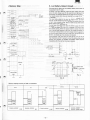
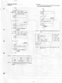
PC-1280
CE-124
CE-152
ea~~e~:1
••••••••••DOOCJ
••••••••••CJCJOCJ
••••••••-CICJCJCJ
········••CJCJO[:j
CE-126P
~:
CE-210M (2KB)
CE-211 M (4KB)
CE-212M (8KB)
CE-2H16M (16KB)
CE-2H32M {32k8)
CE-140F
3. Operating Battery Life and
Consumption Power
PC-1280 battery
Lithium battery:
CR-2032x2pcs
Capacity:
170mAH
10. Open the computer, switch on the power and look at the display.
If it looks like the following with an * displayed, Press the ALL
RESET button.
*
Terminal voltage:
6.0V
11. Turn OFF the power, remove the slot cover, and slide the
Memory Protect Switch to position A.
12. Replace the RAM card, if used.
13. Replace the slot cover and slide the switch back to the LOCK
position.
Consumption current
PC-1280 When OFF:
PC-1280When0N:
45µcA, max.
400µcA, max.
Replacing memory backup cell
The above is at the room temperature of 20°C and may vary
depending on conditions.
The memory backup cell in your PC-1280 has an effective life of
about five years under normal operating conditions.
ate that
temperature extremes can shorten cell life and cause memory
losses. When the memory backup cell was installed at the factory,
a label was attached above the memory protect switch, sho ·ng the
date of installation and a control code.
4. Battery Replacement
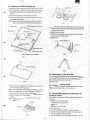
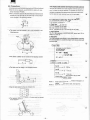
Replacing the operating cells
1. Turn the power OFF.
2. Close the computer and turn it over. Follow the diagrams on
the slot cover to remove the cover.
3. Remove the RAM card if present.
4. Slide the Memory Protect Switch to position B.
THIS IS IMPORTANT and must be done before removing the
operating cells or data and programs in memory will be lost.
Replacing Memory Backup Cell
DO NOT REPLACE THE MEMORY BACKUP CELL WHEN
OPERATING CELLS ARE REMOVED OR WEAK (mil
DISPLAYED WITH POWER ON): MEMORY CONTENTS WILL BE
LOST.
1. Turn OFF the power, close the computer and tum it over.
2. Remove the slot cover and RAM card if present
3. Slide the Memory Protect Switch to position B.
4. Release the screw (1) retaining the cover of the Backup Cell
compartment and remove the cover (2).
5. Replace the cell (3), making sure that the new cell is inserted
with the correct polarity (positive pole down).
6. Slide the Memory Protect Switch back to position A.
7. Replace the slot cover.
Replacing Operating Cells
5. Press the tab (1) and slide open the cell-compartment cover
(2). Remove the two lithium cells (3).
6. Replace the two cells, taking care that they are inserted with
the correct polarity, as shown in the diagram.
7. Replace the cell compartment cover (4).
8. Press the ALL RESET button.
THIS IS IMPORTANT AND MUST BE DONE TO PRESERVE
PROGRAMS AND DATA.
9. Replace the slot cover and slide the switch to the Lock position.
-2-