1
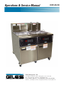
Operations & Service Manual
EOF-20/20
Giles Enterprises, Inc.
FOODSERVICE EQUIPMENT
2750 Gunter Park Drive West • Montgomery, AL 36109 USA
Fax: (334) 272-3561 • Internet: www.gilesent.com
Service Hotline (Toll Free): 1-800-554-4537 (USA & Canada Only)
Form No. 60347 (Release date: 11/99)(Revision date: 11/06/07)(Rev. B)
LIMITED WARRANTY
•
Subject to the terms and conditions of this Limited Warranty as herein stated, all Giles Enterprises,
Inc., Foodservice Equipment and parts purchased new from an authorized Giles Enterprises, Inc.,
representative are warranted as to defects in material or workmanship for a period of 12 months
from the date of installation, provided, however, that with regard to labor costs in connection with
this warranty, see below. All installations must be made by a qualified installing agency in accordance with all applicable codes and/or regulations in the jurisdiction in which installed. Limited warranty coverage is extended to the original owner only and is void if the unit is resold.
•
During the Limited Warranty period, Giles Enterprises, Inc. will replace or recondition, at its factory,
any part or parts of this unit which Giles Enterprises, Inc. inspectors judge defective, provided the
unit has been subjected to normal usage, properly installed, operated and serviced. This Limited
Warranty does not cover cosmetic damage, and damage due to acts of God, accident, misuse, alteration, negligence, abuse of the Giles Foodservice Equipment or the use of unorthodox repair methods. All parts replaced under this Limited Warranty carry only the unexpired term of this Limited
Warranty. Limited Warranty service may be furnished only by an authorized Giles Enterprises, Inc.,
representative.
•
If Limited Warranty service is requested, Giles Enterprises, Inc., will send factory-authorized service representatives to repair, recondition, replace or inspect units of its manufacture with such labor
being rendered without cost to owner for ninety (90) days from the date of installation. Otherwise,
service, including labor and transportation charges or other expenses, in connection with the
removal or installation of any part or parts supplied under this Limited Warranty, are specified on the
original sales contract between the purchaser and the authorized Giles Enterprises, Inc., representative.
•
Giles Enterprises, Inc. reserves the right to change or improve its equipment and parts in any way
without obligation to alter such equipment or parts previously manufactured.
•
Giles Enterprises, Inc. makes no further warranties, express or implied including implied warranties
of merchantability or fitness for a particular purpose, and has no other obligation or liability not
specifically stated herein.
•
Repair or replacement as provided under this limited warranty is the exclusive remedy. Giles
Enterprises, Inc., shall not be liable for any incidental or consequential damages for breach of any
express or implied warranty on this product, except to the extent prohibited by applicable law. Any
implied warranty of merchantability or fitness for a particular purpose on this product is limited in
duration to the duration of this limited warranty.
•
Used Giles Enterprises, Inc., Foodservice Equipment or parts or Giles Enterprises, Inc., Foodservice
Equipment or parts not purchased from an authorized Giles Enterprises, Inc., representative, carry
no warranties, express or implied.
Table Of Contents
Safety
EOF 20/20
. . . . . . . . . . . . . . . . . . . . . . . . . . . . . . . . . . . . . . . . . . . . . . . . . . . . . . . vii
Safety Overview . . . . . . . . . . . . . . . . . . . . . . . . . . . . . . . . . . . . . . . . . . . . . . . . . . . . . . . . . . . . . . . . . . . vii
Specific Safety Precautions . . . . . . . . . . . . . . . . . . . . . . . . . . . . . . . . . . . . . . . . . . . . . . . . . . . . . . . . . . viii
1.
Introduction . . . . . . . . . . . . . . . . . . . . . . . . . . . . . . . . . . . . . . . . . . . . . . 1
1-01.
1-02.
1-03.
1-04.
1-04.1.
1-04.2.
1-04.3.
1-04.4.
1-04.5.
Construction . . . . . . . . . . . . . . . . . . . . . . . . . . . . . . . . . . . . . . . . . . . . . . . . . . . . . . . . . . . . . . 1
Standard Features. . . . . . . . . . . . . . . . . . . . . . . . . . . . . . . . . . . . . . . . . . . . . . . . . . . . . . . . . . 1
Optional Features . . . . . . . . . . . . . . . . . . . . . . . . . . . . . . . . . . . . . . . . . . . . . . . . . . . . . . . . . . 1
Specifications . . . . . . . . . . . . . . . . . . . . . . . . . . . . . . . . . . . . . . . . . . . . . . . . . . . . . . . . . . . . . 2
Overall Dimensions for EOF 20/20 . . . . . . . . . . . . . . . . . . . . . . . . . . . . . . . . . . . . . . . . . . . . . 2
Regulatory Listings . . . . . . . . . . . . . . . . . . . . . . . . . . . . . . . . . . . . . . . . . . . . . . . . . . . . . . . . . 3
Basket Size . . . . . . . . . . . . . . . . . . . . . . . . . . . . . . . . . . . . . . . . . . . . . . . . . . . . . . . . . . . . . . . 3
Vat Size and Capacity . . . . . . . . . . . . . . . . . . . . . . . . . . . . . . . . . . . . . . . . . . . . . . . . . . . . . . . 3
Shipping Specifications (Crated) . . . . . . . . . . . . . . . . . . . . . . . . . . . . . . . . . . . . . . . . . . . . . . . 3
2.
Installation . . . . . . . . . . . . . . . . . . . . . . . . . . . . . . . . . . . . . . . . . . . . . . . 5
2-01.
2-02.
2-03.
2-03.1.
2-04.
2-04.1.
2-05.
Location . . . . . . . . . . . . . . . . . . . . . . . . . . . . . . . . . . . . . . . . . . . . . . . . . . . . . . . . . . . . . . . . . 5
Unpacking . . . . . . . . . . . . . . . . . . . . . . . . . . . . . . . . . . . . . . . . . . . . . . . . . . . . . . . . . . . . . . . . 6
Electrical Requirements . . . . . . . . . . . . . . . . . . . . . . . . . . . . . . . . . . . . . . . . . . . . . . . . . . . . . 7
EOF 20/20 Electrical Specifications . . . . . . . . . . . . . . . . . . . . . . . . . . . . . . . . . . . . . . . . . . . . 7
Electrical Connections . . . . . . . . . . . . . . . . . . . . . . . . . . . . . . . . . . . . . . . . . . . . . . . . . . . . . . 7
Electrical Connections Diagram . . . . . . . . . . . . . . . . . . . . . . . . . . . . . . . . . . . . . . . . . . . . . . . 8
Ventilation of Fryer . . . . . . . . . . . . . . . . . . . . . . . . . . . . . . . . . . . . . . . . . . . . . . . . . . . . . . . . . 8
3.
Overview . . . . . . . . . . . . . . . . . . . . . . . . . . . . . . . . . . . . . . . . . . . . . . . . 9
3-01.
3-02.
3-03.
3-04.
3-05.
3-06.
3-07.
3-08.
EOF-20 Basket Elevator and Baskets . . . . . . . . . . . . . . . . . . . . . . . . . . . . . . . . . . . . . . . . . . 10
EOF-20 Control Panel . . . . . . . . . . . . . . . . . . . . . . . . . . . . . . . . . . . . . . . . . . . . . . . . . . . . . . 12
EOF-20 Left Lower Cabinet Area . . . . . . . . . . . . . . . . . . . . . . . . . . . . . . . . . . . . . . . . . . . . . 14
EOF-20 Right Lower Cabinet Area . . . . . . . . . . . . . . . . . . . . . . . . . . . . . . . . . . . . . . . . . . . . 16
EOF-20 Basket Elevator and Baskets . . . . . . . . . . . . . . . . . . . . . . . . . . . . . . . . . . . . . . . . . . 18
Filter Pan Assembly . . . . . . . . . . . . . . . . . . . . . . . . . . . . . . . . . . . . . . . . . . . . . . . . . . . . . . . 20
Accessories (Included) . . . . . . . . . . . . . . . . . . . . . . . . . . . . . . . . . . . . . . . . . . . . . . . . . . . . . 22
Accessories (Not Included). . . . . . . . . . . . . . . . . . . . . . . . . . . . . . . . . . . . . . . . . . . . . . . . . . 25
4.
Unit Preparation . . . . . . . . . . . . . . . . . . . . . . . . . . . . . . . . . . . . . . . . . 27
4-01.
4-02.
4-03.
4-04.
4-05.
4-06.
Settings before each test . . . . . . . . . . . . . . . . . . . . . . . . . . . . . . . . . . . . . . . . . . . . . . . . . . . 27
Power test . . . . . . . . . . . . . . . . . . . . . . . . . . . . . . . . . . . . . . . . . . . . . . . . . . . . . . . . . . . . . . 29
Heating Element test . . . . . . . . . . . . . . . . . . . . . . . . . . . . . . . . . . . . . . . . . . . . . . . . . . . . . . 30
Filter Pump Test . . . . . . . . . . . . . . . . . . . . . . . . . . . . . . . . . . . . . . . . . . . . . . . . . . . . . . . . . . 31
Perform Boil Out Procedure . . . . . . . . . . . . . . . . . . . . . . . . . . . . . . . . . . . . . . . . . . . . . . . . . 32
Clean Filter Pan. . . . . . . . . . . . . . . . . . . . . . . . . . . . . . . . . . . . . . . . . . . . . . . . . . . . . . . . . . . 32
iii
Table Of Contents
EOF 20/20
5.
Fryer Operation . . . . . . . . . . . . . . . . . . . . . . . . . . . . . . . . . . . . . . . . . . 33
5-01.
5-01.1.
5-01.2.
5-01.3.
5-01.4.
5-01.5.
5-01.6.
5-01.7.
5-01.8.
5-02.
5-03.
5-04.
5-05.
5-06.
Cooking Controller . . . . . . . . . . . . . . . . . . . . . . . . . . . . . . . . . . . . . . . . . . . . . . . . . . . . . . . . 34
Buttons and Functions . . . . . . . . . . . . . . . . . . . . . . . . . . . . . . . . . . . . . . . . . . . . . . . . . . . . . 35
Programming the Cooking Temperature . . . . . . . . . . . . . . . . . . . . . . . . . . . . . . . . . . . . . . . . 36
Programming a Cooking Time. . . . . . . . . . . . . . . . . . . . . . . . . . . . . . . . . . . . . . . . . . . . . . . . 37
Start a cooking time . . . . . . . . . . . . . . . . . . . . . . . . . . . . . . . . . . . . . . . . . . . . . . . . . . . . . . . 38
Cancel the currently running cooking time. . . . . . . . . . . . . . . . . . . . . . . . . . . . . . . . . . . . . . 38
Manually lowering and raising the cooking basket (Basket Elevator Only) . . . . . . . . . . . . . 38
Displaying remaining cooking time. . . . . . . . . . . . . . . . . . . . . . . . . . . . . . . . . . . . . . . . . . . . 39
Displaying the actual temperature of the liquid shortening . . . . . . . . . . . . . . . . . . . . . . . . . 39
Cooking Procedure . . . . . . . . . . . . . . . . . . . . . . . . . . . . . . . . . . . . . . . . . . . . . . . . . . . . . . . . 40
Filtering Liquid Shortening . . . . . . . . . . . . . . . . . . . . . . . . . . . . . . . . . . . . . . . . . . . . . . . . . . 45
Removal of Liquid Shortening . . . . . . . . . . . . . . . . . . . . . . . . . . . . . . . . . . . . . . . . . . . . . . . 48
Normal Shut-Down . . . . . . . . . . . . . . . . . . . . . . . . . . . . . . . . . . . . . . . . . . . . . . . . . . . . . . . . 51
Emergency Shut-Down. . . . . . . . . . . . . . . . . . . . . . . . . . . . . . . . . . . . . . . . . . . . . . . . . . . . . 51
6.
Cleaning . . . . . . . . . . . . . . . . . . . . . . . . . . . . . . . . . . . . . . . . . . . . . . . . 53
6-01.
6-02.
6-03.
Boil-Out Procedure (Cleaning the Fry Pot) . . . . . . . . . . . . . . . . . . . . . . . . . . . . . . . . . . . . . . 53
Cleaning the Filter Pan and replacing Filter Paper after Boil Out . . . . . . . . . . . . . . . . . . . . . 56
Cleaning the Filter Pan and replacing the Filter Paper daily . . . . . . . . . . . . . . . . . . . . . . . . . 57
7.
Troubleshooting . . . . . . . . . . . . . . . . . . . . . . . . . . . . . . . . . . . . . . . . . 59
7-01.
7-02.
7-03.
Temperature Control System . . . . . . . . . . . . . . . . . . . . . . . . . . . . . . . . . . . . . . . . . . . . . . . . 59
Oil Filtration System . . . . . . . . . . . . . . . . . . . . . . . . . . . . . . . . . . . . . . . . . . . . . . . . . . . . . . . 61
Basket Elevator System (Basket Elevator Option Only) . . . . . . . . . . . . . . . . . . . . . . . . . . . . 62
8.
Parts List . . . . . . . . . . . . . . . . . . . . . . . . . . . . . . . . . . . . . . . . . . . . . . . 63
8–01.
8-02.
8-03.
8-04.
8-05.
8-06.
8-07.
8-08.
Parts Ordering and Service Information . . . . . . . . . . . . . . . . . . . . . . . . . . . . . . . . . . . . . . . . 63
EOF-20 Left Control Panel & Front Header. . . . . . . . . . . . . . . . . . . . . . . . . . . . . . . . . . . . . . 64
EOF-20 Left Front Lower Cabinet . . . . . . . . . . . . . . . . . . . . . . . . . . . . . . . . . . . . . . . . . . . . . 66
EOF-20 Left Rear Lower Cabinet . . . . . . . . . . . . . . . . . . . . . . . . . . . . . . . . . . . . . . . . . . . . . 68
EOF-20 Right Control Panel & Front Header. . . . . . . . . . . . . . . . . . . . . . . . . . . . . . . . . . . . . 70
EOF-20 Right Front Lower Cabinet . . . . . . . . . . . . . . . . . . . . . . . . . . . . . . . . . . . . . . . . . . . . 72
EOF-20 Right Rear Lower Cabinet . . . . . . . . . . . . . . . . . . . . . . . . . . . . . . . . . . . . . . . . . . . . 74
Filter Pan . . . . . . . . . . . . . . . . . . . . . . . . . . . . . . . . . . . . . . . . . . . . . . . . . . . . . . . . . . . . . . . . 76
9.
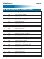
Wiring Diagram . . . . . . . . . . . . . . . . . . . . . . . . . . . . . . . . . . . . . . . . . . 79
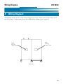
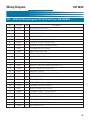
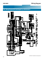
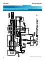
9-01.
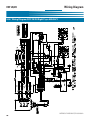
9-02.
9-03.
9-04.
Wiring
Wiring
Wiring
Wiring
iv
Diagram
Diagram
Diagram
Diagram
EOF-20/20
EOF-20/20
EOF-20/20
EOF-20/20
Left Fryer 208-240/60/3 Computer . . . . . . . . . . . . . . . . . . . . . . 80
Right Fryer 208-240/60/3 Computer . . . . . . . . . . . . . . . . . . . . . 82
Left Fryer 480/60/3 Computerr . . . . . . . . . . . . . . . . . . . . . . . . . 84
Right Fryer 480/60/3 Computer . . . . . . . . . . . . . . . . . . . . . . . . 86
Table Of Contents
EOF 20/20
v
EOF 20/20
Notes:
vi
Table Of Contents
Safety
EOF 20/20
Safety
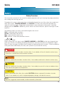
Safety Overview
The instructions contained in this manual have been prepared to aid you in learning the proper procedures
for installing and servicing your unit.
Throughout this manual, safety precautions are identified through the use of the safety alert symbol and
three signal words: DANGER, WARNING, and CAUTION. All safety alert information precedes the
step(s) to which they apply. Suggested, recommended, or other noteworthy information is identified
through the use of NOTES. Additionally, certain words are used to indicate a specific meaning or to add
emphasis.
The following words are used as indicated throughout the manual:
Shall: understood to be mandatory.
Should: understood to be advisory.
May: understood to be permissive.
Will: indicates a future event/condition to occur.
! or !
(Safety Alert Symbol)
Used in conjunction with signal words (DANGER, WARNING, or CAUTION) to alert you of potential personal injury hazards, immediately preceding precautionary measures that pertain to subsequent step(s).
Obey all safety messages that follow these symbols to avoid possible injury or death. Failure to adhere to
safety precautions identified by the safety alert symbol may also void the warranty.
!
DANGER
• Indicates an imminently hazardous situation which, if not avoided, will result in death or serious injury.
Use of this is limited to the most extreme situations.
! WARNING
• Indicates a potentially hazardous situation which, if not avoided, could result in death or serious injury.
! CAUTION
• Indicates a potentially hazardous situation which, if not avoided, may result in minor or moderate injury.
Also used to alert against unsafe practices.
CAUTION
• When used without the safety alert symbol, CAUTION indicates a potentially hazardous situation
which, if not avoided, may result in equipment/property damage, and void the warranty.
NOTE:
• Identifies suggested, recommended, or other noteworthy information.
vii
Safety
EOF 20/20
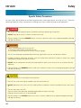
Specific Safety Precautions
For your safety, please observe the following precautions when operating or servicing this unit. Read the
following important safety information to avoid personal injury and/or damage to the equipment.
!
DANGER
• Turn off the unit and unplug the power cord before cleaning or performing maintenance.
• DO NOT hose down the unit’s interior or exterior with water.
• Failure to comply with these DANGER notices will result in death or serious injury, equipment/property damage,
and void the warranty.
! WARNING
• Consult a qualified electrician to ensure that:
•• all electrical specifications and codes are met.
•• circuit breakers and wiring are of sufficient rating and gauge.
• The unit must be properly grounded and all electrical specifications must be met during installation.
• Improper installation, adjustment, alteration, service or maintenance could result in death or serious injury, equipment/property damage, and void the warranty.
• DO NOT use or store gasoline or other flammable liquids or vapors in the vicinity of this or any other electrical
appliance!
• Failure to comply with WARNING notices could result in death or serious injury and equipment/property damage
and void the warranty.
! CAUTION
• The unit must remain in the upright (vertical) position.
• Exercise care when removing the wooden crate from around the unit.
• DO NOT operate the unit unless you fully understand the components and their intended functions (see Section
3).
• The unit and its parts are HOT!
Exercise caution when operating, loading/unloading food, cleaning or servicing.
Wearing of thermal oven mitts is recommended.
• Failure to comply with CAUTION notices may result in minor or moderate injury, equipment/property damage,
and void the warranty.
viii
Safety
EOF 20/20
! CAUTION
• Food products must be maintained at a temperature of 150°F (65.5°C) minimum or in accordance with local or
state health regulations.
•
Fryers must be adequately and properly grounded. Improper grounding may result in electrical shock.
Always refer to your local electrical code to ensure proper grounding of this or any other electrical equipment. Always consult with an electrician or other qualified service person to ensure breakers and wiring are
of sufficient rating and gauge for the equipment being operated.
• Giles Electric Fryers are available from the factory wired for various voltages, phase and hertz. Check the rating
plate on the front of the fryer to determine the correct power supply.
• Ensure the fry kettle is positioned in a secure, safe location with the casters in the locked position.
• Consult an electrician to ensure all electrical specifications have been met and the unit is properly grounded. The
wiring diagrams contained in this manual should aid your electrician in the installation of your fryer.
• Due to the high temperature of shortening in your fryer during cooking, it is extremely important the user exercise caution in the operation of this equipment to avoid personal injury.
• Before attempting to operate the unit, refer to Section 3 to familiarize yourself with the various control functions.
• Be careful not to puncture the filter paper when using the brush to unclog the Drain Valve.
• Allow the unit to cool down a minimum of 15 minutes before cleaning or servicing.
CAUTION
• The electronic components of the Control Panel are impact-sensitive. Exercise care around the Control Panel to
maintain proper operation.
• DO NOT install the unit next to combustible walls and materials. Failure to maintain safe distances may result in
fire.
• During cleaning of the unit:
••
••
••
••
DO
DO
DO
DO
NOT
NOT
NOT
NOT
steam clean.
use products containing chlorine.
use abrasive products, steel wool or scouring pads.
use oven cleaner.
• Failure to comply with these CAUTION notices may result in equipment/property damage and void the warranty.
• Failure to comply with these CAUTION notices may violate local health codes.
• DO NOT Modify, Alter or Add Attachments to this Equipment!
ix
EOF 20/20
Safety
NOTE:
• If the crate in which the unit is shipped is damaged upon receipt, immediately inspect the unit and notify the carrier of any damage to the unit.
• To aid the electrician, an electrical wiring diagram is contained in this manual. Refer to the wiring diagram during
installation or servicing.
• Comply with all appropriate state and/or local heath regulations regarding the cleaning and sanitation of equipment.
x
Introduction
1.
EOF 20/20
Introduction
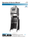
Congratulations on the purchase of your new Giles equipment, Model EOF-20/20 manufactured by Giles
Enterprises, Inc., Montgomery, Alabama (USA), hereafter referred to as "Giles". Every unit is thoroughly
inspected and tested prior to shipment. Proper care and maintenance will ensure years of trouble-free
service.
To help protect your investment in this state-of-the-art cooking equipment, we recommend you take a few
moments to familiarize yourself with the installation, cleaning and maintenance procedures contained in this
manual. Adherence to these recommended procedures minimizes the potential for costly “Down-Time” and
equipment repairs. Please retain this manual for future reference.
1-01. Construction
Model EOF-20/20, exterior and fry vats are constructed of stainless steel.
1-02. Standard Features
Temperature Controller -used to control the temperature of the cooking oil and the cooking time.
Oil Filtration System -used to extend the life of cooking oil.
1-03. Optional Features
Automatic Basket Lift -used to automatically lift cooked product from hot cooking oil at the end of the
cooking cycle.
1
Introduction
EOF 20/20
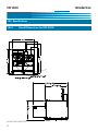
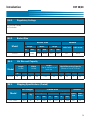
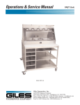
1-04. Specifications
1-04.1.
Overall Dimensions for EOF 20/20
INCHES [MILLIMETERS]
2
Introduction
1-04.2.
EOF 20/20
Regulatory Listings
UL (US and Canada)
UL Sanitation
1-04.3.
Basket Size
Basket Size
Model
1-04.4.
1-04.5.
in
mm
in
mm
in
mm
9.00
228.6
18.50
469.9
5.5
139.7
cubic inch
cubic meter
811
0.013
Vat Size and Capacity
Height
(Top of element to oil
level line
Width
(Inside)
Length
(Inside)
Model
EOF-20
Height
Width
Length
EOF-20
Volume
Liquid Shortening Capacity
(Bottom of Vat to Oil level)
In
mm
In
mm
In
mm
Lbs
Kg
Gal
Lt
20
508
20
508
4 1/2
114
110
50
16
59
Shipping Specifications (Crated)
Crated Size
Net Weight
Model
Length
Lbs
EOF 20/20
884
Width
Volume
Height
Kg
401
In
mm
In
mm
In
mm
76
1930
50
1270
61
1549
Cubic
Feet
Cubic
Meters
134.1
3.8
3
EOF 20/20
Notes:
4
Introduction
Installation
EOF-20/20
2. Installation
This section provides a summary of the procedures necessary for proper installation of your new unit. To prevent personal injury or equipment damage, please ensure the following steps are taken.
2-01. Location
! CAUTION
• DO NOT MODIFY, ALTER OR ADD ATTACHMENTS TO THIS EQUIPMENT
1.
Keep the appliance and surrounding area free and clear from combustible materials. {(3")(7.6cm) for
Fryer.}
2.
Please note wiring diagrams for this appliance are located in the rear of this manual. Ensure the
wiring diagram corresponds with the model being operated.
3.
Please ensure this appliance is electrically grounded in accordance with local codes, or in the absence
of local codes, with the National Electrical Code, ANSI/NFPA NO. 70-1999.
4.
Please provide adequate room for servicing and proper operation of this appliance. Also, provide
adequate ventilation in the operating area where necessary.
5.
Always consult with an electrician or other qualified individual prior to installation.
6.
Ensure voltage and amperage supplied to the unit are as specified on the fryer’s rating plate.
7.
Make sure this unit is in a secure position and will not move. Locking casters are supplied on this
unit--use them!
8.
This appliance is to be installed, used and maintained in accordance with the Standard for Ventilation
Control, and Fire Protection of Commercial Cooking Operations, NFPA 96-1994.
Compliance with the above steps will help to ensure safe and proper installation of your fryer. If you have any
questions concerning these procedures, contact your local Giles distributor or other qualified service person.
5
EOF-20/20
Installation
2-02. Unpacking
Your Giles Fryer may arrive enclosed by a wooden crate. The Fryer is secured to a wooden platform by means
of high-tensile strength strapping.
! CAUTION
• Exercise care when lifting or moving the unit.
• Exercise care when removing the wooden crate from around the unit.
• Failure to comply with these CAUTION notices may result in minor or moderate injury, equipment/property damage, and void the warranty.
NOTE:
• If crate is damaged, immediately inspect the unit and notify the carrier of any damage to the
unit.
1. Carefully cut and remove the plastic shipping wrap and the strapping mentioned above.
2. Use pliers to loosen wire hooks which secure the wooden crate around the fryer. Remove the wooden crate.
3. Carefully remove the fryer from the shipping platform. Your new fryer is extremely heavy, the uncrated weight for the EOF-20/20 is 584 lbs (265 kg), only use a fork lift when lifting this equipment, refer
to 2-03.
6
EOF-20/20
EOF-20/20
2-03. Electrical Requirements
! CAUTION
• Fryers must be adequately and properly grounded.
Improper grounding may result in electrical
shock. Always refer to your local electrical code to ensure proper grounding of this or any other
electrical equipment. Always consult with an electrician or other qualified service person to ensure
breakers and wiring are of sufficient rating and gauge for the equipment being operated.
The EOF-20/20 is available from the factory in the voltages and phases listed below. Check the rating plate on
the rear of the fryer to determine the correct power supply.
2-03.1. EOF-20 Electrical Specifications
Voltage
Phase
Amps
L1
L2
L3
Circuit Breaker
required
Watts
208
1
24,000
115
115
---
150
208
3
24,000
72
46
72
80
240
1
24,000
100
100
---
125
240
3
24,000
68
44
68
75
480
3
24,000
34
22
34
50
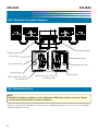
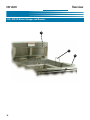
2-04. Electrical Connections
1. Install appropriate Circuit Breakers in Main Breaker Box! See Table 2-04.
2. Connect Flexible Conduit from Main Breaker Box to Quick Disconnect Box.
3. Connect Flexible Conduit from Quick Disconnect Box to the Fryer. Allow enough Conduit so Fryer can
be moved away from the wall for cleaning and servicing. See Figure 2-05.1.
4. Open Fryer Door and remove Service Box Cover. See Figure 2-05.1.
5. Connect the electrical ground wire between the Terminal Block Ground Lug and a proper earth ground.
6. Route appropriate size Power Wires to the Fryer.
7.
Connect the Power Wires to the appropriate Terminal Blocks located in the Service Box. See Figure 204.1.
8. Reinstall Service Box Cover and close the Fryer Door.
7
EOF-20/20
EOF-20/20
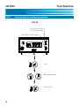
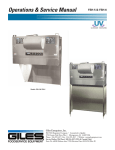
2-04.1. Electrical Connections Diagram
Flexible Conduit
Flexible Conduit
Service Box
Terminal Blocks
Service Box Cover
Terminal Blocks
Power Wires from QuickDisconnect Box
Service Box Cover
Ground Lug
Power Wires from QuickDisconnect Box
Service Box
2-05. Ventilation of Fryer
NOTE:
•Guidelines for proper ventilation system requirements differ from location to location. Always
consult with local authorities to ensure compliance.
Consult a professional ventilation or heating and air conditioning company for assistance in designing a
Ventilation hood for this unit.
8
Overview
EOF-20/20
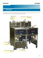
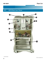
3. Overview
The following section provides a brief overview of the components, functions, and accessories of the unit.
Please review this section carefully before proceeding any further.
EOF-20 Baskets
and Basket
Hanger
Figure 3-07.
EOF-20 Baskets and Basket Lift
Figure 3-04.
EOF-20 Control
Panel
Figure 3-05.
EOF-20 Lower Cabinet Area
Figure 3-06.
Filter Pan Assembly
Figure 3-08.
9
Overview
EOF-20/20
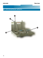
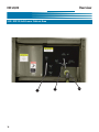
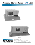
3-01. EOF-20 Basket Elevator and Baskets
1
*2
4
3
10
Overview
EOF-20/20
! CAUTION
• Always use Oven Mitts when using any of these parts. Parts will become very hot during normal use.
3-01. Basket Elevator (Optional) and Baskets
Item
Description
1
Basket Carrier (2)
2
Elevator (2)
3
Crumb Screen
4
Basket (2)
Function
Used to hold the basket in the correct position when the
basket is lifted or lower by the elevator.
Used to lower and lift the basket from the Fry Pot.
Used inside the Fry Pot to prevent excess breading or product from contacting the Heating Elements.
Used for cooking product.
11
Overview
EOF-20/20
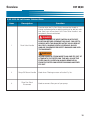
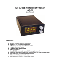
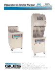
3-02. EOF-20 Control Panel
3
2
6
5
1
4
7
12
Overview
EOF 20/20
3-02. EOF-20 Control Panel
Item
Description
1
Power Switch
Function
The Power Switch is used to turn power ON or OFF to the
unit.
2
Heat Switch
The Heat Switch is used to turn the power to the elements
ON or OFF. Place the Heat Switch in the OFF position when
programming the controller or shutting down the unit. Place
in the ON position when ready to heat the oil.
3
Controller
The Electronic Controller is used for setting a cooking temperature and cooking times.
High-Limit Indicator
The Red High-Limit Indicator Light is illuminated as a result
of power being shut off to the fryer’s heating elements by
the built-in solid-state control circuit as a safeguard against
overheating. Should this light come on during operation,
refer to the Troubleshooting, Section 7, of this manual.
NEVER ATTEMPT TO COOK IF THE HIGH-LIMIT LIGHT IS
ON!
5
Heat Indicator Light
The Orange Heat Indicator Light will be on when the Heat
Switch is in the ON position and the heating elements are
heating the oil. The light will go on and off at various times
as the oil temperature is maintained.
6
Power Indicator Light
4
7
Elevator Switch
The Green Power Light is on whenever the fryer’s Power
Switch is in the ON position.
The Elevator Switch is used to turn the Elevator power on or
off. If the switch is ON the Elevator will lower when a cooking cycle starts and rise when a cooking cycle ends. If the
switch is OFF the Elevator will not operate.
13
Overview
EOF-20/20
3-03. EOF 20 Left Lower Cabinet Area
1
14
2
3
Overview
EOF 20/20
3-03. EOF-20 Left Lower Cabinet Area
Item
Description
Function
Used to drain the Fry Pot. Always ensure the Handle is
closed and locked prior to adding cooking oil or boil out solution. Your fryer will not heat if this Drain Valve Handle is not
completely closed and locked.
!
1
Drain Valve Handle
DANGER
ALWAYS ENSURE THE HEAT SWITCH IS IN THE OFF
POSITION BEFORE OPENING THIS VALVE. FAILURE TO
COMPLY WITH THIS DANGER NOTICE COULD RESULT
IN A FIRE, CAUSING DEATH OR SERIOUS INJURY
AND/OR EQUIPMENT/PROPERTY DAMAGE AND VOID
THE WARRANTY.
! WARNING
NEVER DRAIN OIL FROM MORE THAN ONE FRY POT AT
A TIME INTO THE FILTER PAN. THIS WILL CAUSE THE
FILTER PAN TO OVERFLOW. ALWAYS REMOVE OIL
FROM THE FILTER PAN BEFORE DRAINING ANOTHER
FRY POT.
2
Pump Oil Return Handle
3
Filter Pan Quick
Disconnect
Used when Filtering to return oil to the Fry Vat.
Used to connect filter pan to fryer pump.
15
Overview
EOF 20/20
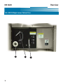
3-04. EOF 20 Right Lower Cabinet Area
3
16
2
1
Overview
EOF 20/20
3-04. EOF-20 Left Lower Cabinet Area
Item
Description
Function
Used to drain the Fry Pot. Always ensure the Handle is
closed and locked prior to adding cooking oil or boil out solution. Your fryer will not heat if this Drain Valve Handle is not
completely closed and locked.
!
1
Drain Valve Handle
DANGER
ALWAYS ENSURE THE HEAT SWITCH IS IN THE OFF
POSITION BEFORE OPENING THIS VALVE. FAILURE TO
COMPLY WITH THIS DANGER NOTICE COULD RESULT
IN A FIRE, CAUSING DEATH OR SERIOUS INJURY
AND/OR EQUIPMENT/PROPERTY DAMAGE AND VOID
THE WARRANTY.
! WARNING
NEVER DRAIN OIL FROM MORE THAN ONE FRY POT AT
A TIME INTO THE FILTER PAN. THIS WILL CAUSE THE
FILTER PAN TO OVERFLOW. ALWAYS REMOVE OIL
FROM THE FILTER PAN BEFORE DRAINING ANOTHER
FRY POT.
2
Pump Oil Return Handle
3
Discharge Hose Quick
Disconnect
Used when Filtering to return oil to the Fry Vat.
Used to connect discharge hose to fryer.
17
Overview
EOF 20/20
3-05. EOF-20 Basket Hanger and Baskets
1
2
3
18
Overview
EOF 20/20
! CAUTION
• Always use Oven Mitts when using any of these parts. Parts will become very hot during normal use.
3-05. EOF-20 Basket Hanger and Baskets
Item
Description
Function
1
Basket Hanger
Used to hold the basket(s) while excess oil is drained from
the product.
2
Crumb Screen
Used inside the Fry Pot to prevent Baskets, excess breading
or product from contacting the Heating Elements.
3
Basket (2)
Used for cooking product. (Optional on some units)
19
Overview
EOF-20/20
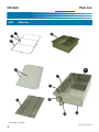
3-06. Filter Pan Assembly
1
3
2
4
7
6
5
20
Overview
EOF 20/20
! WARNING
• Never remove the Filter Pan with Liquid Shortening in the pan. This could cause oil to spill.
Please see section 5-4. Removal of Liquid Shortening.
! CAUTION
• Always use Oven Mitts when using any of these parts. Parts will become very hot during normal use.
3-06. Filter Pan Assembly
Item
Description
Function
1
Hold Down Lever
(4 Levers)
Used to tightly hold down the hold down frame on the filter
paper.
2
Hold Down Frame
Used to tightly hold down the filter paper.
3
Filter Paper
(2 Sheets)
Used to filter finer particles of sediment from the cooking oil.
The system requires (2) pieces of Filter Paper to be used.
4
Filter Pan Screen
Used to elevate the filter paper from the bottom of the filter
pan to allow proper filtration.
5
Filter Pan Crumb Screen
6
Filter Pan
7
Filter Pan Quick
Disconnect Hose
Used to remove larger particles of sediment from the cooking
oil during the filtering process.
Used to filter cooking oil. The Filter Pan is removable for
cleaning and for the changing of the filter paper.
Used to connect to the fryer’s oil filtration system. The hose
must be disconnected before removing the filter pan.
21
Overview
EOF-20/20
3-07.
Accessories (Included)
Part
22
Description/Part
Number
Function
Kettle Drain Brush
P/N: 71025
Used for cleaning the Fry Pot.
Drain Brush, Small
P/N: 73235
Used for cleaning the FFLT drain
Stir Paddle
P/N: 77775
Used for stirring Hot Oil and
Product being cooked.
Fry Vat Clean Brush
P/N: 71100
Used for cleaning Fry Pot and
Elements.
Crumb Shovel
P/N: 30059
Used for removing sediment from
the Filter Pan.
Overview
3-07.
EOF 20/20
Accessories (Included)
Part
Description/Part
Number
Function
L- Shaped Brush
P/N: 73233
Used for cleaning between
elements.
Vat Drain Clean Out
P/N: 36577
Used to clear excessive sediment
build up from the Vat Drain.
Wand Hose
P/N: 33667
Used for removing liquid
shortening from unit.
Note: Not recommended for
washing down the fry pot.
23
Overview
EOF-20/20
3-07.
Accessories (Included)
Part
24
Description/Part
Number
Function
(1) EOF-20 Fry Basket
(Blue Handle)
P/N: 70420
Used for cooking product in the
EOF-10-10 or the EOF-20.
(1) EOF-20 Fry Basket
(Yellow Handle)
P/N: 71109
Used for cooking product in the
EOF-10-10 or the EOF-20.
(2) EOF-20 Fry Screen
P/N: 70083
Used to prevent excess breading or
product from contacting the Heating
Elements.
Product Scoop
P/N: 70430
Used for removing cooked product
when Fry Baskets are not used.
(Optional on some units)
Overview
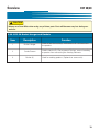
3-08.
EOF 20/20
Accessories (Not Included)
Part
Description/Part
Number
Function
Filter Paper
P/N:60709
Used to filter the cooking oil.
Filter Powder
P/N: 72004
Used to help clean the cooking oil.
Fryer Boil-Out
P/N: 72003
Used to help clean the fry pot.
25
Overview
EOF-20/20
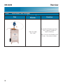
3-08.
Accessories (Not Included)
Part
Description/Part
Number
Giles Oil Caddy
P/N: 79187
Function
A portable oil disposal container
with a capacity of 80lbs of
liquid shortening.
Note: For use with filtered, warm
oil only. No crumbs or debris.
26
Unit Preparation
EOF 20/20
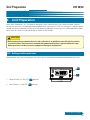
4. Unit Preparation
We at Giles Enterprises, Inc. take pride in the quality of our workmanship. Every effort has been made to
ensure that your unit is in good operating condition when you receive it. Each unit must pass a rigorous quality
control test prior to shipment. To further ensure optimum operation of your new unit, a brief operational checkout of your new fryer must be conducted as set-out in this section.
! CAUTION
• Before attempting to operate the unit, refer to Section 3 to familiarize yourself with the various
control functions. Once you have read and fully understand Section 3, please follow the steps
below precisely in order to prevent equipment damage or malfunction.
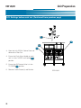
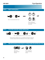
4-01. Settings before each test
Please ensure each unit’s control panel and valves are set to the following before proceeding to each test.
2
1
1. Power Switch is in the OFF 1 position.
EOF-20
2. Heat Switch is in the OFF 2 position.
Continued next page
27
Unit Preparation
EOF 20/20
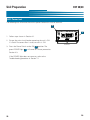
4-01. Settings before each test (Continued from previous page)
3
3
4
3
3. Open the Left EOF-20 Cabinet Door and
remove the Filter Pan.
4. Ensure the Drain Valve Handle on each
unit is in the CLOSED and Locked 3
position.
5. Ensure the Oil Diverter Valve is in the
TO FRYER 4 position.
6. Remove Crumb Screen(s) and Baskets.
28
EOF-20/20
Unit Preparation
EOF 20/20
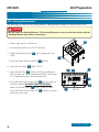
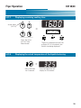
4-02. Power test
The following test will ensure the unit has power. Perform this test on each unit.
2
1
1. Follow steps shown in Section 4-1.
2. Ensure the main circuit breaker powering the unit is ON.
If a Quick Disconnect Box is used, ensure it is ON.
EOF-20
3. Press the Power Switch to the ON 1 position. The
green POWER light 2 will come on. Please proceed to
Section 4-3.
If the POWER light does not come on, refer to the
Troubleshooting procedure in Section 7-1.
29
29
Unit Preparation
EOF 20/20
4-03. Heating Element test
The following test will ensure the Heating Element is being powered. Perform this test on each Fry Pot.
!
DANGER
•DO NOT touch the Heating Elements.
The Heating Elements are very hot and skin contact with the
Heating Elements may result in severe burns.
1
1. Follow steps shown in Section 4-1.
2. Ensure Power Switch is in the OFF position.
3. Wipe the Heating Element 1 with a sponge wet with
water.
1
4. Press the Power Switch to the ON 2 position.
5. Wait until the display 3 reads “HOLD.”
3
6. Press the Set Temp 4 button, the Display should read
350. If it does not set the temperature to 350, see Section
5-1.2. Programming the Cooking Temperature.
4
7
2
7.
Press the Heat Switch to the HEAT 7 position. Leave in
the HEAT position NO MORE THAN 10 SECONDS.
Note: If the Scroll Display 8 reads “Check Oil Level,”
press the Power Switch to the OFF 9 position, then proceed to the next step.
9
8
EOF-20
Continued next page
30
Unit Preparation
EOF 20/20
4-03. Heating Element test (Continued from previous page)
8. Press the Heat Switch to the OFF 10 position
9. The wet element should quickly dry within 15 seconds.
Proceed to Section 4-4.
If the Heating Element does not dry within 15-30 seconds, refer to the Troubleshooting procedure in Section
7-1.
10
EOF-20
4-04. Filter Pump Test
The following test will ensure the Filter Pump is operating correctly.
1. Follow steps shown in Section 4-1.
2. Open Cabinet Door.
3. Place the palm of your hand over the Quick
Disconnect 1 for the Filter Pan Hose.
4. Briefly press the Pump Switch to the PUMP 2
position then press the Pump Switch to the OFF
3 position. If suction is felt on the palm, the
pump is operating correctly. Proceed to Section
4.5.
If no suction is felt, refer to the Troubleshooting
procedure in Section 7-2.
1
2
3
31
EOF 20/20
Unit Preparation
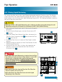
4-05. Perform Boil Out Procedure
Perform a Boil Out Procedure to remove any particles or debris that may have been left due to shipping.
Follow Section 6-1 Boil Out Procedure. After performing the Boil Out Procedure proceed to Section 4-6.
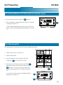
4-06. Clean Filter Pan
Thoroughly clean the Filter Pan to remove any particles or debris that may have been left due to shipping.
Follow Section 6-2 Cleaning the Filter Pan and replacing Filter Paper after Boil Out.
The fryer’s preparation is now complete. Please proceed to the Fryer Operation Section.
32
Fryer Operation
EOF 20/20
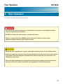
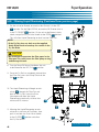
5. Fryer Operation
This section describes how to operate the unit.
!
DANGER
• Turn off the unit and turn off the fryer’s circuit breaker in the main circuit breaker box before
cleaning or performing maintenance.
• DO NOT hose down the unit’s interior or exterior with water.
• Failure to comply with these DANGER notices will result in death or serious injury,
equipment/property damage, and void the warranty.
! CAUTION
• Ensure the unit is positioned in a secure, safe location with the casters in the locked position.
• Consult an electrician to ensure all electrical specifications have been met and the unit is properly grounded. The wiring diagrams contained in this manual should aid your electrician in the
installation of your fryer.
• Due to the high temperature of cooking oil in your fryer during cooking, it is extremely important the user exercise caution in operation this equipment to avoid personal injury.
33
Fryer Operation
EOF 20/20
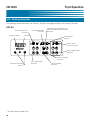
5-01. Cooking Controller
The following section describes the functions, features and programming of the Cooking Controller.
EOF-20
LEFT TIMER SELECT
BUTTON
SCROLL DISPLAY
SET TEMPERATURE
BUTTON
TEMPERATURE & TIMER ADJUSTMENT & ELEVATOR UP OR DOWN
BUTTONS
DISPLAY
ALARM RESET
BUTTON
RIGHT TIMER
SELECT BUTTON
RIGHT TIMER MENU
BUTTONS
RIGHT ELEVATOR
BUTTON*
DISPLAY INDICATOR
LIGHTS
* -Basket Elevator Option Only
34
LEFT TIMER MENU
BUTTONS
LEFT ELEVATOR
BUTTON*
Fryer Operation
5-01.1.
EOF 20/20
Buttons and Functions
Used to set and display cooking temperature.
Used to increase or decrease cooking time and temperature.
Used to set and recall cooking times.
Used to silence alarm.
EOF-20: Used to select Left or Right Basket Elevator. (Basket Elevator Option Only)
Used to select the Left Basket Timer.
Used to select the Right Basket Timer.
Used to display cooking times and temperature.
Scrolls various status information.
35
Fryer Operation
EOF 20/20
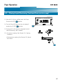
5-01.2.
Programming the Cooking Temperature
EOF-20
Ensure Heat Switch is
in the OFF position
Press Power Switch to ON
Press
Adjust temperature
Press to set
36
Fryer Operation
5-01.3.
EOF 20/20
Programming a Cooking Time
EOF-20
Ensure Heat Switch is
in the OFF position
Press Power Switch to ON
or
Press and hold both the
desired Basket Timer (left
or right) and the desired
Menu Key for 5 seconds
+
Adjust the time
Press the desired Basket
Timer again to set
or
37
Fryer Operation
EOF 20/20
5-01.4.
Start a cooking time
x2
or
Press the desired Basket Timer.
Press the desired
menu button twice to
start timer.
5-01.5.
Cancel the currently running cooking time
+
or
+
Press the desired Basket Timer twice to cancel.
(Basket Elevator Option Only) If cancelled and the Basket Elevator
has been lowered, the Basket Elevator will raise when cancelled.
5-01.6.
Manually lowering and raising the cooking basket (Basket Elevator Only)
Press the
desired Basket
Elevator.
38
Press to lower or
raise the cooking
basket.
Fryer Operation
5-01.7.
EOF 20/20
Displaying remaining cooking time
Active Menu
(LED lit)
=
Press the active
(LED lit) Timer
Menu button
5-01.8.
The time is displayed and the Left
or Right LED is lit to identify the
Basket time being displayed.
Displaying the actual temperature of the liquid shortening
=
Press and Hold
for 5 seconds
Actual temperature will
display for 20 seconds
39
Fryer Operation
EOF 20/20
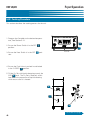
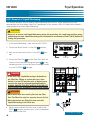
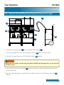
5-02. Cooking Procedure
This section describes the cooking process for the unit.
1. Program the Controller to the desired temperature, See Section 5-1.2.
2
2. Ensure the Power Switch is in the OFF 1
position.
1
EOF-20
3. Ensure the Heat Switch is in the OFF 2 position.
4. Ensure the Drain Valve is pushed in and locked
in the CLOSED 3 position.
5. Fill the Fry Pot with liquid shortening to only the
ADD 4 level. The Fry Pot is filled only to this
level due to the expansion of liquid shortening
which occurs after it is heated.
4
3
3
Continued next page
40
Fryer Operation
EOF 20/20
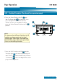
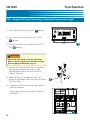
5-02. Cooking Procedure (Continued from previous page)
6. Press the Power Switch to the ON 5 position. The Power Light 6 will come on. If the
unit is equipped with the Basket Elevator
Option, and you want to engage this option,
press the Basket Elevator Switch to the ON 7
position.
6
10
11
8
9
5
NOTE:
• If when pressing the Power Switch to the ON
position, an alarm sounds and the Scroll
Display reads “Drain Open -Close and Push
Reset”, follow step 4, above, then press Alarm
Reset on the Cooking Controller.
7
EOF-20
7. Press the HEAT Switch to the ON 8 position.
The Heat Light 9 will come on, the display will
read “HOLD” 10 and the Scroll Display will read
“Oil Heating” 11 . The Oil will begin to heat to the
programmed temperature .
Continued next page
41
Fryer Operation
EOF 20/20
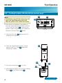
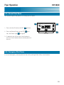
5-02. Cooking Procedure (Continued from previous page)
NOTE:
• The following step will help remove any cold
area in the Liquid Shortening which will
allow the product to be cooked more evenly.
11
12
13
8. Once the oil has reached it’s first preheat, an
alarm will sound and the Scroll Display will read
“Stir Oil and Push Reset” 11 . Using the supplied Stir Paddle, thoroughly stir the Cooking Oil,
then press the Alarm Reset 12 button.
EOF-20
9. When the Heat Light 13 goes out the Oil is
heated to the set point.
10. Check the Liquid Shortening level, it should
now be at the FULL Level 14 . Add Liquid
Shortening if needed.
14
16
17
11. Place the Crumb Screen 15 in Fry Pot.
15
12. (Basket Elevator Option Only) Place the Cooking
Basket 16 on the Basket Carrier 17 .
Continued next page
42
Fryer Operation
EOF 20/20
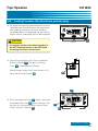
5-02. Cooking Procedure (Continued from previous page)
13. We recommend placing uncooked product into the
Cooking Basket with the basket in the up position,
then lowering the basket into the oil. However,
uncooked product may be placed into the Cooking
Basket after the Cooking Basket has been lowered.
19
18
! CAUTION
•
EOF-20
Use extreme caution when placing product in
the HOT liquid shortening, as the HOT liquid
shortening could cause severe burns.
14. (Basket Elevator Option Only) Press the desired
Basket Lift Button 18 . Then press the Down
Arrow 19 . Cooking Basket will lower.
(Basket Hanger Option Only) Place Baskets in Fry
Pot on top of Crumb Screen 20 .
20
21
15. Press desired Basket Timer 21 Button , then press
the desired Menu Time 22 Button two times. The
the time will start counting down and the Scroll
Display will read “Cooking” 23 .
23
22
EOF-20
Continued next page
43
Fryer Operation
EOF 20/20
5-02. Cooking Procedure (Continued from previous page)
25
16. After 60% of the cooking time has elapsed from the
selected cooking time, the stir cycle alarm will sound and
the Scroll Display will read “Stir Product” 24 . Using the
Stir Paddle 25 and wearing Oven Mitts stir the product,
then press the Alarm Reset Button 26 .
17. (Basket Elevator Option) At the end of the cooking
time an alarm will sound and the Display will read
“DONE” 27 . The Scroll Display will read “Left
Timer” or “Right Timer” 24 . The Cooking Basket
28 and the cooked product will automatically raise
from the Hot Liquid Shortening. Press the Alarm
Reset 26 Button to silence the alarm.
27
26
24
(Basket Hanger) At the end of the cooking time an
alarm will sound and the Scroll Display will read
“DONE” 27 . The Scroll Display will read “Left
Timer” or “Right Timer” 24 . Using Oven Mitts lift
EOF-20
the Basket 28 from the cooking oil and hang the
Basket on the top bar of the Basket Hanger 29 .
Press the Alarm Reset 26 Button to silence the
alarm.
18. Allow the cooked product to adequately drain.
19. Using Oven Mitts remove the Basket and place
cooked product on a landing table or in an appropriate container.
28
28
29
20. • To continue cooking on the unit return to step 6 of
this procedure.
• To shut down the unit, see Section 5-5 Normal
Shut-Down.
Basket Elevator
44
Basket Hanger
Fryer Operation
EOF 20/20
5-03. Filtering Liquid Shortening
This section describes how to filter Liquid Shortening through the built-in filtration system. The filtration
system recirculates the Liquid Shortening through the Filter Pan, Filter Paper and Cooking Vat. By following this process you will increase the Liquid Shortening life up to 50%. The Cooking Controller is preset to
alert you to filter every fourth load.
! CAUTION
• Never try to filter cold Liquid Shortening, this could clog the filter pump and damage the unit.
Liquid Shortening must be heated to a minimum of 200°F (93°C) before filtering.
1. After cooking the fourth load in the Fry Pot the oil will need to
be filtered.
2. On the unit to be filtered, press the Heat Switch to the OFF
1 position.
3. Open the Cabinet Door. Wearing Oven Mitts, disconnect the
Filter Pan Quick Disconnect Hose 2 then remove the Filter
1
Pan 3 from the unit.
4. Ensure the Filter Pan has (2) sheets of Filter Paper installed
correctly.
5. Add one package (4.8 ounces) of Giles Filter Powder (Part No.
72004) into the Filter Pan.
6. Ensure the Filter Pan Cover is in place, then reposition the
Filter Pan in the unit and reconnect the Filter Pan Quick
Disconnect Hose 2 .
!
EOF-20
DANGER
• In the next step Liquid Shortening is drained into the Filter
Pan. Failure to ensure the fryer’s Heat Switch is in the OFF
position prior to draining may result in fire from the
exposed Heating Elements. ALWAYS ENSURE THE HEAT
SWITCH IS IN THE OFF POSITION BEFORE DRAINING LIQUID SHORTENING.
5
2
! WARNING
• Never drain both sides into the Filter Pan! The Filter Pan
only has capacity for one Fry Pot.
• Never disconnect the Filter Pan from unit with Liquid
Shortening in the Filter Pan.
3
Continued next page
45
Fryer Operation
EOF 20/20
5-03. Filtering Liquid Shortening (Continued from previous page)
7.
On the unit to be filtered, ensure the Heat Switch is in the OFF
1 position. On the Right EOF-20, ensure the Oil Diverter Valve is
in the TO FRYPOT 5 position. On the unit to be filtered, slowly
unlock and pull the Drain Valve Handle to the OPEN 6 position.
This will allow Liquid Shortening to drain into the Filter Pan.
6
NOTE:
• If the Fry Pot does not drain use the supplied
Kettle Drain Brush to break up the crumbs in the
Fry Pot Drain.
7
! CAUTION
• Be careful not to puncture the filter paper in the
filter pan. This could cause the filter pump to clog
and damage the unit.
8. Turn the Pump Oil Return Handle on the unit
to be filtered to the VAT FILL 7 position.
8
9. Once the Fry Pot has completely drained into
the Filter Pan, press the Pump Switch to the
ON 8 position.
10. The Liquid Shortening will begin to recirculate 9 through the Filter Pan and
back to the Fry Pot. Leave the Drain
Valve open and allow the Liquid
Shortening to continually circulate for a
minimum of 5 minutes.
OR
9
9
7
11. Allowing the Liquid Shortening to recirculate for a minimum of 5 minutes, then
push in and lock the Drain Valve Handle
to the CLOSE 10 position and allow
the Fry Pot to refill.
7
10
Continued next page
46
Fryer Operation
EOF 20/20
5-03. Filtering Liquid Shortening (Continued from previous page)
12. After the Fry Pot has refilled, press the Pump
Switch to the OFF 11 position.
13. Turn the Pump Oil Return on the unit being filtered to the CLOSE 12 position.
11
14. Ensure the Fry Pot contains the proper level of
Liquid Shortening, add if needed.
15. • To continue cooking, See Section 5-2, Cooking
Procedure.
• To discontinue cooking, See Section 5-5, Normal
Shut Down.
12
47
Fryer Operation
EOF 20/20
5-04. Removal of Liquid Shortening
This section describes how to remove Liquid Shortening from the unit. Liquid Shortening must be
removed from the fryer before a Boil Out is performed. In this section a Giles Oil Caddy (not included) is
used to dispose the used Liquid Shortening.
! CAUTION
• Never try to remove cold Liquid Shortening using this procedure, this could clog the filter pump
and damage the unit. Liquid Shortening must be heated to a minimum of 200°F (93°C) before following this procedure.
1. If the Liquid Shortening is cold, heat to 200°F (93°C).
2
2. Ensure the Power Switch is in the ON 1 position.
3. Next, ensure the Heat Switch is in the OFF 2 position.
1
EOF-20
4. Ensure the Filter Pan 3 and the Filter Pan Cover are
in place. Ensure the quick disconnect hose 4 is connected the to unit. Ensure the Pump Discharge Handle
is in the TO FRYER 5 position.
!
DANGER
4
• In the next step, Liquid Shortening is drained into
the Filter Pan. Failure to ensure the fryer’s Heat
Switch is in the OFF position prior to draining may
result in fire from the exposed Heating Elements.
ALWAYS ENSURE THE HEAT SWITCH IS IN THE OFF
POSITION BEFORE DRAINING LIQUID SHORTENING.
! WARNING
• Never drain more than one Fry Pot into the Filter
5
3
Pan! The Filter Pan only has capacity for one Fry Pot.
• Never disconnect the Filter Pan from unit with
Liquid Shortening in the Filter Pan.
5. Slowly unlock and pull the Drain Valve Handle to the
OPEN 7 position and allow the Fry Pot to completely
drain into the Filter Pan.
48
7
Continued next page
Fryer Operation
EOF 20/20
5-04. Removal of Liquid Shortening (Continued from previous page)
8
12
13
11
10
9
6. Connect the Discharge Hose 8 to the Discharge Hose Coupling 9 .
7.
Place the discharge end into a Hot Oil Disposal Container 10 (Giles Oil Caddy shown).
8. Turn the Oil Diverter Valve to the TO DISCHARGE HOSE 11 position.
! WARNING
• During the next step be sure the wear Oven Mitts if holding the Discharge Hose, as the hose will
become very hot.
9. Press the Pump Switch to the PUMP 12 position and allow the liquid shortening to pump into the
Disposal Container.
10. After the Liquid Shortening is removed from the Filter Pan, press the Pump Switch to the OFF 13
position.
Continued next page
49
Fryer Operation
EOF 20/20
5-04. Removal of Liquid Shortening (Continued from previous page)
11. Press the Power Switch to the OFF 14 position.
12. Push and lock the Drain Valve to the CLOSED
15 position.
EOF-20
13. Turn the Oil Diverter Valve handle to the TO FRYPOT 16 position.
14
! WARNING
• During the next step be sure the wear Oven
Mitts as the Discharge Hose and the Discharge
Hose Coupling will become very hot.
14. Remove the Discharge Hose from the Discharge
Hose Coupling and drain the excess Liquid
Shortening remaining in the hose into the Oil
Disposal Container.
15. Allow the Filter Pan to thoroughly cool, then
remove and thoroughly clean the Filter Pan and the
Filter Pan Cover.
15
16. • To perform a Boil Out on the unit see Section 6-1
Boil Out Procedure.
• To shut down the unit see Section 5-5 Normal
Shut-Down.
16
50
Fryer Operation
EOF 20/20
5-05. Normal Shut-Down
This section explains the process of shutting the unit down.
3
1
1. Press the Heat Switch to the OFF 1 position.
2. Press the Power Switch to the OFF 2 position, the Power Light 3 will go off.
2
EOF-20
3. If required, turn off the fryer circuit breaker in
the main circuit breaker box to remove power to
the unit.
5-06. Emergency Shut-Down
In case of emergency, remove power to the unit by turning off the facility circuit breaker.
51
EOF 20/20
Notes:
52
Fryer Operation
Cleaning
EOF 20/20
6. Cleaning
This section describes the cleaning operations for the EOF-20/20. The unit should be cleaned on a daily
basis.
!
DANGER
• DO NOT hose down the unit’s interior or exterior with water.
• Failure to comply with these DANGER notices will result in death or serious injury,
equipment/property damage, and void the warranty.
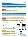
6-01. Boil-Out Procedure (Cleaning the Fry Pot)
This section describes how to clean the Fry Pot in the unit. This process is referred to as "Boil-Out". A
"Boil-Out" must be performed before cooking with new equipment and should be performed each time liquid shortening is discarded from the unit.
For proper operation of the fryer, the Boil-Out procedure should be carried out every 7 to 14 days.
!
DANGER
• DO NOT under any circumstances leave the fryer unattended during this procedure as heat must
be carefully monitored to prevent the Fry Pot from overflow due to boiling. Overflow of the Fry
Pot may result in serious equipment damage.
1. Remove Liquid Shortening from the unit, see Section 5-4.
Removal of Liquid Shortening.
2
2
2. Ensure the Drain Valve Handle is pushed in and locked in the
CLOSED 1 position and the Power Switch is in the OFF
6 position.
OR
3. Fill the Fry Pot with water to the FULL level 2 .
4. Following the directions on the Giles Boil-Out Container, add
the recommend amount of Boil-Out to the Fry Pot.
1
1
! CAUTION
• If using a cleaner other than Giles Boil-Out pay close
attention to the instructions listed on the container. Many
commercially available cleaners are caustic chemicals
which require special precautions. If used improperly,
these chemicals may cause damage to the fryer and
potential injury to the user.
1
Continued next page
53
Cleaning
EOF 20/20
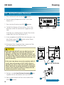
6-01. Boil Out Procedure (Continued)
5. Press the Power Switch to the ON 3 position.
4
5
6. Set the Cooking Temperature to 200°F (93°C) See
Section 5-1.2.
3
Press the Heat Switch to the HEAT 4 position.
7.
6
8. The Boil Out Solution will heat to 200°F (93°C). See
directions on Boil Out container for suggested cycle
time.
EOF-20
If desired, set a cooking time to a Basket Timer for the
suggest Boil Out time, See Section 5-1.3.
9. At the completion of the Boil Out Cycle time press the
Heat Switch to the OFF 5 position and the Power
Switch to the OFF 6 position.
10. Disconnect Quick Disconnect Hose, remove the Filter
Pan, then remove the Filter Pan Cover.
! CAUTION
• In the next step DO NOT drain the Boil-Out into the
OR
Filter Pan! Contents are corrosive and will cause
damage to the Filter Pan, the Hold-Down Frame, and
the Filter Pump. Failure to comply may result in minor
or moderate injury, equipment/property damage, and
void the warranty.
• In the next step always ensure the container which is
8
8
used is heat resistant up to 300°F (148°C). Plastic is
generally not safe as it may melt or break. Metal containers which do not leak are preferable to containers
made of other materials. Failure to comply with this
caution may result in serious injury.
7 NOT THE FILTER PAN
11. Position a suitable Heat Resistant Container 7 (not
supplied with the unit) beneath the Fryer Drain.
12. Slowly unlock and pull the Drain Valve Handle to the
OPEN 8 position.
54
8
Continued next page
Cleaning
EOF 20/20
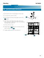
6-01. Boil Out Procedure (Continued)
13. Rinse and flush the Fry Pot thoroughly with tap water.
14. Dry fry pot with a clean dry towel.
9
15. Push and lock in the Drain Valve Handle to the CLOSE
9 position.
16. Clean Filter Pan and replace Filter Paper; follow directions in Section 6-2, Cleaning the Filter Pan and replacing
Filter Paper after the Boil Out.
17. Re install Filter Pan Cover .
18. Position Filter Pan 10 under unit and connect Filter Pan
Quick Disconnect Hose 11 .
19. To begin cooking on the unit, see Section 5-2.
10
11
55
Cleaning
EOF 20/20
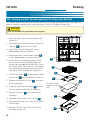
6-02. Cleaning the Filter Pan and replacing Filter Paper after Boil Out
This section explains the process for cleaning the Filter Pan and the replacement of the Filter Paper. This
process should be carried out each time you perform a Boil Out Procedure (Section 5-5).
! CAUTION
• Use Thermal Mitts for protection from hot parts.
1. Follow the Normal Shut-Down procedure, see
Section 5-5.
2. Disconnect Quick Disconnect hose, remove the
Filter Pan 1 and the Filter Pan Cover .
3. Clean Filter Pan Cover thoroughly, using a
biodegradable, none toxic cleaner.
4. Remove and clean Crumb Screen Screen 3 ,
using a biodegradable, none toxic cleaner.
5. Using metal Crumb Scoop provided with the
unit, remove the accumulated breading and
residue from the edge of the Hold Down Frame
and surface of the Filter Paper. This will help prevent breading from getting underneath the new
Filter Paper, which could prevent a good seal.
1
3
4
6. Turn the four Levers 4 to disengage the HoldDown Frame 5 from the bottom of Filter Pan.
7.
Remove the Hold Down Frame 5 , then clean
and dry thoroughly.
8. Grasp one end of the Filter Paper 6 and carefully roll up both sheets, then discard them.
9. Remove the Screen 7 , then clean and dry
thoroughly.
5
6
Discard (2) used,
replace with (2)
new.
7
10. Thoroughly clean and dry the Filter Pan 8 .
11. Reassemble the Filter Pan using (2) new sheets
of Filter Paper.
12. Reinstall Filter Pan Cover, then the Filter Pan
Assembly into the unit.
56
8
Cleaning
EOF 20/20
6-03. Cleaning the Filter Pan and replacing the Filter Paper daily
This section explains the process for cleaning the Filter Pan and the replacement of the Filter Paper daily.
This process should be carried out daily.
! CAUTION
• Use Thermal Mitts for protection from hot parts.
1. Follow the Normal Shut-Down procedure, see Section 5-5.
2. Disconnect Quick Disconnect hose, remove the Filter Pan
1 and the Filter Pan Cover .
3. Clean Filter Pan Cover thoroughly, using a biodegradable,
none toxic cleaner.
4. Remove and clean Crumb Screen Screen 3 ,using a
biodegradable, none toxic cleaner.
5. Using metal Crumb Scoop provided with the unit, remove
the accumulated breading and residue from the edge of the
Hold Down Frame and surface of the Filter Paper. This will
help prevent breading from getting underneath the new
Filter Paper, which could prevent a good seal.
1
3
6. Turn the four Levers 4 to disengage the Hold-Down
4
Frame 5 from the bottom of Filter Pan.
7.
Remove the Hold-Down Frame 5 , then clean and dry
thoroughly.
5
6
Discard this
used sheet
8. Grasp top sheet 6 of Filter Paper by one end, carefully
roll up and discard.
Maintain this
9. Grasp bottom sheet 7 of Filter Paper by both ends
used sheet
and remove; retain for reuse.
10. Remove the Screen 9 , then clean and dry thoroughly.
7
8
New sheet
11. Thoroughly clean and dry the Filter Pan 10 .
9
12. Reassemble the Filter Pan using (1) new sheet of Filter
Paper 8 , placed under maintained sheet.
13. Reinstall Filter Pan Cover, then the Filter Pan Assembly into
the unit.
10
57
EOF 20/20
Notes:
58
Cleaning
Troubleshooting
7.
EOF 20/20
Troubleshooting
This section describes troubleshooting procedures for the unit. Refer to the wiring diagrams in Section 9
for more detailed analysis.
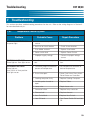
7-01.
Temperature Control System
Problem
FRYER WILL NOT TURN ON:
No power light
Probable Cause
Repair Procedure
A. Not connected to power
source.
A. Connect to power source.
B. Bad fuse or circuit breaker.
B. Check fuse or breaker.
C. Fuse holder cracked.
C. Replace fuse holder.
D. Power switch bad.
D. Replace Power Switch.
E. Improper supply voltage.
E. Connect to proper voltage
source.
FRYER WILL NOT HEAT:
Power light on. Heat light not on.
A. Heat Switch not in Heat position.
A. Place Heat Switch in Heat position.
FRYER WILL NOT HEAT:
Power light on.
Heat Switch in Heat position.
Heat light not on.
A. Controller programmed below A. Set temperature controller to
present oil temperature.
desired temperature.
B. Drain Valve open.
B. Close Drain Valve. Press Alarm
Reset Button on Controller.
C. Cooking computer faulty.
C. Replace Cooking Computer.
D. Variable probe shorted or
open.
D. Replace Probe.
E. Loose wire.
E. Repair loose wire.
F.
F. Replace faulty contactor.
Contactor failure.
G. Element bad.
G. Replace element.
H. Heat Switch bad.
H. Replace Heat Switch.
I.
I. Turn Power Switch Off and Add
Oil.
Low Oil Level
59
Troubleshooting
EOF 20/20
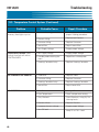
7-01. Temperature Control System (Continued)
Problem
FRYER HEATING SLOW: (slow
recovery) Heat light stays on.
FRYER HEATS SLOW: (short
cycling) Heat light off and on
CONTINUOUSLY.
OIL TEMPERATURE ERRATIC:
OIL SMOKING:
60
Probable Cause
Repair Procedure
A. Incorrect Cooking procedures.
A. Consult Operations Manual for
proper Cooking procedure.
B. Element failing.
B. Replace bad Element.
C. Contactor failing.
C. Replace Contactor.
D. Loose Wire.
D. Repair Loose Wire.
E. Low Supply Voltage.
E. Supply proper Voltage.
A. Low supply Voltage.
A. Supply proper Voltage.
B. Variable probe touching element.
B. Reposition variable probe.
C. Cooking Controller faulty.
C. Replace Cooking Controller.
A. Probe bad.
A. Replace Probe.
B. Contactor failing.
B. Replace Contactor.
C. Cooking Controller faulty.
C. Replace Cooking Controller.
D. Loose Wire.
D. Repair loose Wire.
A. Old Oil.
A. Change Oil.
B. Over Temperature.
B. Check temperature setting.
C. Dirty Element.
C. Clean Elements, using Fry Vat
cleaning brush.
D. Element failure.
D. Replace Element.
E. Improper element voltage.
E. Supply proper Voltage.
F. Low Oil level.
F. Keep Oil at FULL Level.
Troubleshooting
EOF 20/20
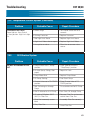
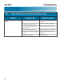
7-01. Temperature Control System (Continued)
Problem
FRYER WILL NOT HEAT:
Power light on. Heat Switch
in Heat position. High Limit light
On.
Probable Cause
Repair Procedure
A. Power surge.
A. Turn Power Switch off for 5
seconds.
B. Sticking Contactor.
B. Replace Contactor.
C. Bad High Limit Board.
C. Replace High Limit Board.
D. High Limit Probe short or open. D. Replace High Limit Probe.
E. Line spikes or noise.
7-02.
E. Filter Line or remove noise
source.
Oil Filtration System
Problem
OIL NOT RETURNING TO FRY
POT:
Probable Cause
Repair Procedure
A. Pump Switch not in “Pump”
position.
A. Place Selector Switch in
“Filter/Pump” position.
B. Air Leak (hose, fittings, filter
paper).
B. Repair Air Leak.
C. Pump Motor Bad.
C. Replace Pump Motor.
D. Oil Pump Sticking.
D. Free Stuck Pump.
E. Diverter Valve not in TO FRYER E. Place Diverter Valve in TO
FRYER position.
position.
F. Boil Out being run through
Pump.
F. Disassemble and Re-Oil Pump.
G. Old Oil allowed to sit in Pump.
G. Run Clean Oil through Pump.
H. Oil cold or Oil below 200°F
(93°C) in Filter Pan.
H. Remove Filter Pan and remove
cold oil from Filter Pan.
I. Filter Pan incorrectly assembled.
I. Assembly Filter Pan correctly.
J. Dirty Filter Pan.
J. Clean Filter Pan.
61
Troubleshooting
EOF 20/20
7-03.
Basket Elevator System (Basket Elevator Option Only)
Problem
BASKET WILL NOT GO UP OR
DOWN
Probable Cause
Repair Procedure
A. Power not on.
A. Press Power Switch to ON
position.
B. Cooking Controller faulty.
B. Replace Cooking Controller.
C. Elevator microswitch out of
adjustment.
C. Adjust Elevator microswitch.
D. Elevator microswitch bad.
D. Replace Elevator microswitch.
E. Elevator Switch not in On posi- E. Press Elevator Switch to On
tion.
position.
F. Elevator Motor bad.
62
F. Replace Motor.
Parts List
EOF 20/20
8. Parts List
This section lists various parts that are available for replacement on the unit.
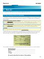
8–01. Parts Ordering and Service Information
If you require assistance or need repairs, please contact your area developer for a service agency in your
area. For further assistance, please contact the Giles Enterprises, Inc. corporate office at the following
phone numbers:
IN THE UNITED STATES, CANADA or MEXICO
Please call 1-800-554-4537 during normal business hours, 8:00AM-5:00PM Central Time Zone. For emergency equipment repair service, after normal business hours, call 1-800-554-4537, extension 314.
IN ALL OTHER COUNTRIES
Please call 1-334-272-1457 during normal business hours, 8:00AM-5:00PM Central Time Zone; For emergency equipment repair service, after normal business hours call, 1-334-272-1457 extension 314.
INTERNET
Please visit our website on the world wide web at: www.gilesent.com.
The goal of the Giles team of professionals is to provide you with the highest quality of service and assistance. You can help us accomplish this by obtaining the following information and having it readily available when calling. The information is recorded on the Data Plate attached to the side of the unit.
The area below may be helpful in recording information from the Data Plate for use as a quick reference.
Model Number: ______________________________________
Serial Number: ______________________________________
Phase:
___________________________________________
Voltage: ___________________________________________
Be ready to describe the nature of the problem.
63
Parts List
EOF 20/20
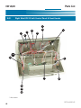
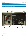
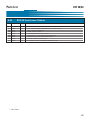
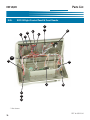
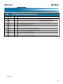
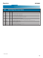
8-02.
Right Side EOF-20 Left Control Panel & Front Header
7
6
4
3
1
8
5
2
*16
15
9
11
10
12
13
14
* -Not shown
REF #: 60221-01
64
Parts List
8-02.
Item
01
02
03
04
05
06
07
08
09
10
11
12
13
14
15
16
EOF 20/20
EOF-20 Control Panel & Front Header
Part No.
23755
20315
20315
23751
24222
21101
21102
37616
21190
21052
20326
38214
38213
38215
21052
23782
Qty.
1
1
1
1
1
1
1
1
1
1
1
1
1
1
1
1
Description
THERMOSTAT, SAFETY, WATLOW, 450DEG
THERMOCOUPLE,13.5",STRAIGHT,J TYPE, (REQUIRES P/N 45111 FERRULE)
THERMOCOUPLE,13.5",STRAIGHT,J TYPE, (REQUIRES P/N 45111 FERRULE)
TERMINAL BLOCK, MA106,6 POLE
THERMOCOUPLE, VARIABLE, SINGLE, (REQUIRES P/N 45111 FERRULE)
SOCKET, RELAY, 8 PIN, 300V, 10A, CR-5
RELAY, 8 PIN, 240V, 10A, CR-5
TRANSFORMER & ADAPTER PLATE, ASSY,60HZ
SWITCH, ROCKER, ON-OFF, 250V, 20A, DPST
SWITCH,ROCKER,ON-NONE-ON,250V,20A,DPDT
CONTROLLER,COMPUTER,WATLOW,TIME/TEMP
LIGHT, INDICATOR, RED,250VAC
LIGHT, INDICATOR, ORANGE,250V
LIGHT, INDICATOR, GREEN,250VAC
SWITCH,ROCKER,ON-NONE-ON,250V,20A,DPDT
SONALERT, 250V, CONTINUOUS BEEP
* -Not shown
65
Parts List
EOF 20/20
8-03.
EOF-20 Left Front Lower Cabinet
1
2
3
*7
*4
*8
5
9
*6
* -Not shown
REF #: 60221-02
66
Parts List
8-03.
Item
01
02
*03
*04
05
*06
*07
*08
09
EOF 20/20
EOF-20 Front Lower Cabinet
Part No.
21164
21051
35151
45755
39258
40818
21157
35236
41900
Qty.
1
1
1
1
1
1
1
1
1
Description
POWER DIST,TERMINAL BLOCK
LUG, 1/0-2/0 COPPER TERMINAL 125A 1/4" BOLT HOLE
WELD ASSY., DOOR FINAL
VALVE, 3-WAY, 1/2NPT
HANDLE,DRAIN PULL,WELD ASSY
VALVE,BALL,1-1/4",DRAIN,SINGLE THREADEND
SWITCH, LIMIT, 15A, 250V DRAIN SWITCH
COVER, SERVICE CONNECTION
COUPLING, QUICK DICONNECT,FEMALE,FIL PAN
* -Not shown
67
Parts List
EOF 20/20
8-04.
EOF-20 Left Rear Lower Cabinet
4
3
5
2
6
1
* -Not shown
REF #: 60221-03
68
Parts List
8-04.
Item
01
02
02
02
03
04
05
06
EOF-20 Left Rear Lower Cabinet
Part No.
32260
20003
20004
24257
20513
21900
21950
70912
EOF 20/20
Qty.
2
4
4
4
2
2
2
1
Description
CONTACTOR,ASSY,4 POLE,40A,W/QUENCH
ELEMENT, 6000W, 208V, EOF-20
ELEMENT, 6000W 240V, EOF-20
ELEMENT, 6000W 480V, EOF-20
BREAKER, CIRCUIT,277V,50A,6 POLE
FUSE, 15-AMP, SC-15
HOLDER, FUSE, 300V, 15A
PUMP/MOTOR ASSY
* -Not shown
69
Parts List
EOF 20/20
8-05.
EOF-20 Right Control Panel & Front Header
7
6
4
3
1
8
5
2
*16
15
9
11
10
12
13
14
* -Not shown
REF #: 60221-04
70
Parts List
8-05.
Item
01
02
03
04
05
06
07
08
09
10
11
12
13
14
15
EOF 20/20
EOF-24 Control Panel & Front Header
Part No.
23755
20315
24222
20315
23751
21101
21102
37616
21190
21052
20326
38214
38213
38215
23782
Qty.
1
1
1
1
1
1
1
1
1
1
1
1
1
1
1
Description
THERMOSTAT, SAFETY, WATLOW, 450DEG
THERMOCOUPLE,13.5",STRAIGHT,J TYPE, (REQUIRES P/N 45111 FERRULE)
THERMOCOUPLE, VARIABLE, SINGLE, WOG-D, (REQUIRES P/N 45111 FERRULE)
THERMOCOUPLE,13.5",STRAIGHT,J TYPE, (REQUIRES P/N 45111 FERRULE)
TERMINAL BLOCK, MA106,6 POLE
SOCKET, RELAY, 8 PIN, 300V, 10A
RELAY, 8 PIN, 240V, 10A
TRANSFORMER & ADAPTER PLATE, ASSY,60HZ
SWITCH, ROCKER, ON-OFF, 250V, 20A, DPST
SWITCH,ROCKER,ON-NONE-ON,250V,20A,DPDT
CONTROLLER,COMPUTER,WATLOW,TIME/TEMP
LIGHT, INDICATOR, RED,250VAC
LIGHT, INDICATOR, ORANGE,250V
LIGHT, INDICATOR, GREEN,250VAC
SONALERT, 250V, CONTINUOUS BEEP
* -Not shown
71
Parts List
EOF 20/20
8-06.
EOF-20 Right Front Lower Cabinet
1
*8
4
2
*6
7
*5
*3
* -Not shown
REF #: 60221-05
72
Parts List
8-06.
Item
01
02
*03
04
*05
*06
07
*08
EOF-24 Front Lower Cabinet
Part No.
21051
21164
35151
41699
35236
40818
39260
40784
EOF 20/20
Qty.
1
1
1
1
1
1
1
1
Description
LUG, 1/0-2/0 COPPER TERMINAL 125A 1/4" BOLT HOLE
POWER DIST,TERMINAL BLOCK
DOOR FINAL, WELD ASSY
COUPLING, QUICK DISCONNECT, FEMALE
COVER, SERVICE CONNECTION
VALVE,BALL,1-1/4",DRAIN,SINGLE THREADEND
HANDLE,DRAIN PULL, WELD ASSY
VALVE,BALL,1/2",S/S
73
Parts List
EOF 20/20
8-07.
EOF-24 Rear Lower Cabinet
6
8
7
9
5
10
11
4
3
2
1
*12
* -Not shown
74
REF #: 60221-06
Parts List
8-07.
Item
01
02
02
02
03
04
05
06
07
07*
08
09
10
11
*12
EOF 20/20
EOF-20 Right Rear Lower Cabinet
Part No.
32260
20003
20004
24257
32158
22878
36457
39167
24277
20513
39403
35052
21900
21950
35125
Qty.
2
4
4
4
2
2
2
2
1
2
2
2
2
2
1
Description
CONTACTOR,ASSY,4 POLE,40A,W/QUENCH
ELEMENT, 6000W, 208V, EOF-20
ELEMENT, 6000W 240V, EOF-20
ELEMENT, 6000W 480V, EOF-20
ELEV MOTOR & QUENCHARC, ASSY 208/240
SWITCH, 250V, 10A, DOUBLE SNAP ACTION
ELEVATOR, BASKET, ASSY, EOF
BRONZE BEARING WITH GROOVE
TRANSFORMER, 1.5kw, 480V TO 240V, (480V MODEL ONLY)
BREAKER, CIRCUIT,50A,277V,6 PL, SER TRIP (208V OR 240V MODEL ONLY)
BASKET CARRIER,. ASSY
BAR, ELEVATOR LIFT, EOF
FUSE, 15AMP, SC-15
HOLDER, FUSE, 300V, 15A, SC 0 TO 15
WELD ASSY., BACK PANEL
* -Not shown
75
Parts List
EOF 20/20
8-08.
Filter Pan
8
10
7
6
9
12*
4
3
5
2
11
* -Complete assembly
76
1
REF #: 60221-09
Parts List
8-08.
Item
01
02
03
04
05
06
07
08
09
10
11
12*
Filter Pan
Part No.
40649
43307
44150
30039-8
40181
35810
30040-4
54526
60709
36213
43302
35813
EOF 20/20
Qty.
4
1
1
4
1
1
4
4
2
1
1
1
Description
CASTER, SWIVEL, 2.563IN, PLATE MNT
HOSE, 1/2NPT X 7.625, STEEL BRAIDED
FITTING, BRASS,MALE,1/2NPT,QUICK DISCONN
STUD, FILTER PAN SUPPORT FRAME
SCREEN, FILTER PAN (EOF-20)
FRAME, FILTER PAPER HOLD DWN, WELD ASSY
STUD, FILTER PAN HOLD DOWN FRAME
CASTING, LEVER,FILTER PAN,HOLDDOWN FRAME
PAPER, FILTER, GFSE, 15-3/8 X 32-3/8
CRUMB SCREEN, WELD ASSY, FILTER PAN
HOSE, 1/2 NPT X 18.000, STEEL BRAIDED
FILTER PAN, FINAL, ASSY, EOF-20/20, (P/N 36213 NOT INCLUDED)
* -Complete assembly
77
EOF 20/20
Notes:
78
Parts List
Wiring Diagram
EOF 20/20
9. Wiring Diagram
The following section contains various Wiring Diagrams for the unit. Please check the Serial Plate on the
rear of each unit, as shown below, for the units Model Name, Voltage, Hertz, and Phase.
Left
EOF-20
Serial Plate
Right
EOF-20
Serial Plate
Rear View
79
Wiring Diagram
EOF 20/20
9-01. Wiring Diagram EOF 20/20 Left Fryer 208-240/60/3
WIRING DIAGRAM P/N:39391-D
80
Wiring Diagram
EOF 20/20
9-01. BOM for Wiring Diagram EOF 20/20 Left Fryer 208-240/60/3
Item
Part No.
Qty.
Description
1
21102
1
RELAY, 8 PIN, 240V, 10A
2
21101
1
SOCKET, RELAY, 8 PIN, 300V, 10A
3
21900
2
FUSE, 15-AMP, SC-15
4
21950
2
HOLDER, FUSE
5
20004
4
ELEMENT, ROUND, 6000W, 240V,
5
20003
4
ELEMENT, ROUND, 6000W, 208V
6
23782
1
SONALERT, 250V, CONTINOUS BEEP
7
23751
1
TERMINAL BLOCK, MA106
8
20402
1
INDICATOR LIGHT, RED
9
21190
1
SWITCH, ROCKER, ON-OFF
10
70912
1
PUMP/MOTOR ASSY
11
25200
1
WIRE, 22-GA, MULTI-LEAD
12
32260
2
CONTACTOR, ASSY, 4-POLE
13
21157
1
SWITCH, LIMIT, 15A, 250V DRAIN SWITCH
14
21164
1
BLOCK, POWER DISTRIBUTION
15
20513
2
BREAKER, CIRCUIT
16
23755
1
THERMOSTAT, SAFETY, WATLOW, 450DEG
17
20326
1
CONTROLLER, N7
18
37616
1
TRANSFORMER
19
38365
1
ASSY, FUSE
20
21196
4
TERMINAL, BLOCK, JUMPER
21
20327
1
BOARD CONNECTOR, 16-PIN
22
23900
1
THERMOCOUPLE - J, 3-IN, SINGLE
23
21052
2
SWITCH,ROCKER,ON-OFF-ON
24
20315
1
THERMOCOUPLE, J-TYPE, STRAIGHT, 13.5-IN
25
20399
1
INDICATOR LIGHT, AMBER
26
20398
1
INDICATOR LIGHT, GREEN
27
20328
4
PIN, CONNECTOR
81
Wiring Diagram
EOF 20/20
9-02. Wiring Diagram EOF 20/20 Right Fryer 208-240/60/3
WIRING DIAGRAM P/N:39392-D
82
Wiring Diagram
EOF 20/20
9-02. BOM for Wiring Diagram EOF 20/20 Right Fryer 208-240/60/3
Item
Part No.
Qty.
Description
1
21102
1
RELAY, 8 PIN, 240V, 10A
2
21101
1
SOCKET, RELAY, 8 PIN, 300V, 10A
3
21900
2
FUSE, 15-AMP, SC-15
4
21950
2
HOLDER, FUSE
5
20004
4
ELEMENT, ROUND, 6000W, 240V,
5
20003
4
ELEMENT, ROUND, 6000W, 208V
6
23782
1
SONALERT, 250V, CONTINOUS BEEP
7
23751
1
TERMINAL BLOCK, MA106
8
20402
1
INDICATOR LIGHT, RED
9
21190
1
SWITCH, ROCKER, ON-OFF
10
--------
-
-------------
11
25200
1
WIRE, 22-GA, MULTI-LEAD
12
32260
2
CONTACTOR, ASSY, 4-POLE
13
21157
1
SWITCH, LIMIT, 15A, 250V DRAIN SWITCH
14
21164
1
BLOCK, POWER DISTRIBUTION
15
20513
2
BREAKER, CIRCUIT
16
23755
1
THERMOSTAT, SAFETY, WATLOW, 450DEG
17
20326
1
CONTROLLER, N7
18
36457
2
ASSY, MOTOR & QUENCHARC, ELEV
19
22878
2
SWITCH, 250V, 10A, DOUBLE SNAP ACTION
20
20007
2
CONNECTOR, 4-PIN, IN-LINE RECEPTACLE
21
20008
2
CONNECTOR, 4-PIN, IN-LINE PLUG
22
23900
1
THERMOCOUPLE - J, 3-IN, SINGLE
23
21052
2
SWITCH,ROCKER,ON-OFF-ON
24
20315
1
THERMOCOUPLE, J-TYPE, STRAIGHT, 13.5-IN
25
20399
1
INDICATOR LIGHT, AMBER
26
20398
1
INDICATOR LIGHT, GREEN
27
20328
4
PIN, CONNECTOR
28
20327
1
BOARD CONNECTOR, 16-PIN
29
21291
6
CONNECTOR, PIN, FEMALE
30
21290
6
CONNECTOR, PIN, MALE
31
21196
4
TERMINAL, BLOCK, JUMPER
32
38365
1
ASSY, FUSE, CONTROLLER
33
37616
1
TRANSFORMER
83
EOF 20/20
Wiring Diagram
9-03. Wiring Diagram EOF 20/20 Left Fryer 480/60/3
WIRING DIAGRAM P/N:39292-A
84
Wiring Diagram
EOF 20/20
9-03. BOM for Wiring Diagram EOF 20/20 Left Fryer 480/60/3
Item
Part No.
Qty.
Description
1
21102
1
RELAY, 8 PIN, 240V, 10A
2
21101
1
SOCKET, RELAY, 8 PIN, 300V, 10A
3
21900
2
FUSE, 15-AMP, SC-15
4
21950
2
HOLDER, FUSE
5
24257
4
ELEMENT, ROUND, 6000W, 480V
6
23782
1
SONALERT, 250V, CONTINOUS BEEP
7
23751
1
TERMINAL BLOCK, MA106
8
20402
1
INDICATOR LIGHT, RED
9
21190
1
SWITCH, ROCKER, ON-OFF
10
24277
1
TRANSFORMER, 1.5kw, 480V TO 240V
11
25200
1
WIRE, 22-GA, MULTI-LEAD
12
32260
2
CONTACTOR, ASSY, 4-POLE
13
21157
1
SWITCH, LIMIT, 15A, 250V DRAIN SWITCH
14
21164
1
BLOCK, POWER DISTRIBUTION
15
70912
1
PUMP/MOTOR ASSY
16
23755
1
THERMOSTAT, SAFETY, WATLOW, 450DEG
17
20326
1
CONTROLLER, N7
18
37616
1
TRANSFORMER
19
38365
1
ASSY, FUSE
20
21196
4
TERMINAL, BLOCK, JUMPER
21
20327
1
BOARD CONNECTOR, 16-PIN
22
23900
1
THERMOCOUPLE - J, 3-IN, SINGLE
23
21052
2
SWITCH,ROCKER,ON-OFF-ON
24
20315
1
THERMOCOUPLE, J-TYPE, STRAIGHT, 13.5-IN
25
20399
1
INDICATOR LIGHT, AMBER
26
20398
1
INDICATOR LIGHT, GREEN
27
20328
4
PIN, CONNECTOR
85
EOF 20/20
Wiring Diagram
9-04. Wiring Diagram EOF 20/20 Right Fryer 480/60/3
WIRING DIAGRAM P/N: 39293-A
86
Wiring Diagram
EOF 20/20
9-04. BOM for Wiring Diagram EOF 20/20 Right Fryer 480/60/3
Item
Part No.
Qty.
Description
1
21102
1
RELAY, 8 PIN, 240V, 10A
2
21101
1
SOCKET, RELAY, 8 PIN, 300V, 10A
3
21900
2
FUSE, 15-AMP, SC-15
4
21950
2
HOLDER, FUSE
5
24257
4
ELEMENT, ROUND, 6000W, 480V
6
23782
1
SONALERT, 250V, CONTINOUS BEEP
7
23751
1
TERMINAL BLOCK, MA106
8
20402
1
INDICATOR LIGHT, RED
9
21190
1
SWITCH, ROCKER, ON-OFF
10
24277
1
TRANSFORMER, 1.5kw, 480V TO 240V
11
25200
1
WIRE, 22-GA, MULTI-LEAD
12
32260
2
CONTACTOR, ASSY, 4-POLE
13
21157
1
SWITCH, LIMIT, 15A, 250V DRAIN SWITCH
14
21164
1
BLOCK, POWER DISTRIBUTION
15
37616
1
TRANSFORMER
16
23755
1
THERMOSTAT, SAFETY, WATLOW, 450DEG
17
20326
1
CONTROLLER, N7
18
36457
2
ASSY, MOTOR & QUENCHARC, ELEV
19
22878
2
SWITCH, 250V, 10A, DOUBLE SNAP ACTION
20
20007
2
CONNECTOR, 4-PIN, IN-LINE RECEPTACLE
21
20008
2
CONNECTOR, 4-PIN, IN-LINE PLUG
22
23900
1
THERMOCOUPLE - J, 3-IN, SINGLE
23
21052
2
SWITCH,ROCKER,ON-OFF-ON
24
20315
1
THERMOCOUPLE, J-TYPE, STRAIGHT, 13.5-IN
25
20399
1
INDICATOR LIGHT, AMBER
26
20398
1
INDICATOR LIGHT, GREEN
27
20328
4
PIN, CONNECTOR
28
20327
1
BOARD CONNECTOR, 16-PIN
29
21291
6
CONNECTOR, PIN, FEMALE
30
21290
6
CONNECTOR, PIN, MALE
31
21196
4
TERMINAL, BLOCK, JUMPER
32
38365
1
ASSY, FUSE, CONTROLLER
87
EOF 20/20
Notes:
88
Wiring Diagram
FOODSERVICE EQUIPMENT
Giles Enterprises, Inc.
2750 Gunter Park Drive West • Montgomery, Al 36109 USA
(334) 272-1457 • Service Hotline 1-800-554-4537 (USA & Canada Only) • FAX (334) 272-3561 • www.gilesent.com
Form No. 60437 (Release date: 11/99)(Revision date: 11/06/07)(Rev B)