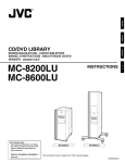
1
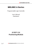
TEST REPORT
IEC 60950-1: 2005 (2nd Edition) and/or EN 60950-1:2006
Information technology equipment-Safety requirements
Part 1: General requirement
Report Reference No........................ : VITE10013NBS
Tested by (+ signature)...................... :
/Tony Li
Review by (+ signature)
:
/Andy Zhang
Approved by (+ signature) ................. :
/Tracy Qi
Date of issue ...................................... : Aug 16, 2010
Contents............................................ : Total 27 pages
Attachments:
Attachment A Product photos
: 2 pages
This report is based on a blank test report that was prepared by KEMA using information obtained from the
TRF originator(see below)
Testing Laboratory Name ............ : Shenzhen VITE Technology Co.,Ltd
Address ........................................... : Suite 2123, Building 4, Hongfa Centre, Central Area Baoan,
Baoan District, Shenzhen, Guangdong, 518101, P.R. China
: Same as above.
Testing location
Applicant
Name.................................................. : Foshan Amplitec Tech Development Co., Ltd
Address .............................................. : No.1 Room,Second Floor ,No.40,First East Tonghua Rd , Foshan City ,
Guangdong Province , China 528000
Standard............................................. : EN 60950-1:2006
Non-standard test method ................. : N/A
Procedure deviation
: N/A
Test procedure
: CCA
Copyright reserved to the bodies participating in the CENELEC Certification Agreement (CCA)
Test Report From/blank test report
Test Report Form No.
: VITE10013NBS
Test Report Form(s) Originator: VITE
Master TRF
: 07-06
Test item Description ........................ : Mobile Phone Signal Repeater
Trademark.......................................... : Amplitec
Report No.: VITE10013NBS
1
Model No............................................ : C20C-GDW,
C10C/15C/20C/24C/27C/30C-EGSM
C10C/15C/20C/24C/27C/30C-GSM
C10C/15C/20C/24C/27C/30C-DCS
C10C/15C/20C/24C/27C/30C-WCDMA
C10C/15C/20C/24C/27C/30C-ED
C10C/15C/20C/24C/27C/30C-EW
C10C/15C/20C/24C/27C/30C-GD
C10C/15C/20C/24C/27C/30C-GW
C10C/15C/20C/24C/27C/30C-DW
C10C/15C/20C/24C/27C/30C-GDW
Manufacturer ...................................... : Foshan Amplitec Tech Development Co., Ltd
Rating(s)............................................. : Input: 100-240Vac 1.6A 50-60Hz Output:12Vdc, 5.0A (by AC adapter)
Particulars;test item vs.test requirements
Equipment mobility
: Fixed Equipment
Operating condition
: Continuous
Mains supply tolerance
: +10%,-10%(charge from a approved adapter)
Tested for IT power systems
: N/A
IT testing, phase-phase voltage
: N/A
Class of Equipment
: Class Ⅲ equipment
Mass of equipment (kg)
: 6.2kg
Protection against ingress of water : IPX0
Test case verdicts
Test case does not apply to the test object.................. : N(.A.)
Test item does meet the requirement .......................... : P(ass)
Test item does not meet the requirement .................... : F(ail)
Testing
Date of receipt of test item ........................................... : Aug 02, 2010
Date(s) of performance of test……………...................: Aug 09, 2010
General remarks
This report shall not be reproduced except in full without the written approval of the testing laboratory.
The test results presented in this report relate only to the item(s) tested.
"(see appended table)" refers to a table appended to the report.
“(see remark #)” refers to a remark appended to the report.
Throughout this report a point is used as the decimal separator.
Until otherwise specified, all tests are done under normal ambient condition 25℃±10,Max RH:75%
And air pressure of 860 mbar to 1060 mbar.
All models are same except the type model only.
Name and address of production site (Factory):
Foshan Amplitec Tech Development Co., Ltd
No.1 Room,Second Floor ,No.40,First East Tonghua Rd , Foshan City , Guangdong Province , China 528000
Report No.: VITE10013NBS
2
Copy of marking plate:
Mobile Phone Signal Repeater
Model No.: C20C-GDW
POWER: 12V
,5.0A
Foshan Amplitec Tech Development Co., Ltd
Report No.: VITE10013NBS
3
EN 60950-1
Clause
Requirement – Test
1
GENERAL
P
1.5
Components
P
1.5.1
General
P
Comply with IEC 60950 or relevant component
standard
1.5.2
Evaluation and testing of components
Result - Remark
Verdict
Components which were found
to affect safety aspects comply
with the requirements of this
standard or with the safety
aspects of the relevant IEC/EN
component standards.(see
appended table1.5.1)
P
Components which are certified
to IEC/EN and/or national
standards are used correctly
within their ratings, Components
not covered by IEC/EN
standards are tested under the
conditions present in the
equipment.
P
Dimensions (mm)of mains plug for direct plug-in
N
Torque and pull test of mains plug for direct plugin;torque(Nm);pull(N)
N
1.5.3
Thermal controls
No any thermal controls
N
1.5.4
Transformers
Approved power adapter
P
1.5.5
Interconnecting cables
Ditto
P
1.5.6
Capacitors in primary circuits
Ditto
P
1.5.7
Double insulation or reinforced insulation bridged by
components
Ditto
P
1.5.7.1
General
See below
P
1.5.7.2
Bridging capacitors
N
1.5.7.3
Bridging resistors
N
1.5.7.4
Accessible parts
N
1.5.8
Components in equipment for IT power systems
N
1.6
Power interface
P
1.6.1
AC power distribution systems
TN power system for power
adapter
P
1.6.2
Input current
(see appended table 1.6.2)
P
1.6.3
Voltage limit of hand-held equipment
Voltage<250V
P
1.6.4
Neutral conductor
ClassⅢ equipment, no earth
provided
N
Report No.: VITE10013NBS
4
EN 60950-1
Clause
Requirement – Test
1.7
Marking and instructions
P
1.7.1
Power rating
N
Rated voltage(s)or voltage range(s)(V)
Result - Remark
100-240Vac(by AC adapter )
Symbol for nature of supply, for d.c. only
Verdict
P
P
Rated frequency or rated frequency
range(Hz)
Marked with power adapter
P
Rated current (mA or A)
1.6A
P
Manufacturer’s name or trade mark or
identification mark
Foshan Amplitec Tech Development Co., Ltd
P
Type/model or type reference
C20C-GDW
P
Symbol for Class II equipment only
Class Ⅲ equipment
N
Other symbols
Additional symbols or markings do not
cause misunderstanding
P
Certification marks
P
1.7.2
Safety instructions
P
1.7.3
Short duty cycles
Equipment is designed for continuous
operation
N
1.7.4
Supply voltage adjustment
No such devices used
N
Methods and means of adjustment,
reference to installation instructions
N
1.7.5
Power outlets on the equipment
N
1.7.6
Fuse identification(marking, special fusing
characteristics. Cross-reference)
N
1.7.7
Wining terminals
See below
N
1.7.7.1
Protective earthing and bonding terminals
ClassⅢ equipment, no protective earthing
N
1.7.7.2
Terminal for a.c. mains supply conductors
P
1.7.7.3
Terminal for d.c. mains supply conductors
P
1.7.8
Controls and indicators
P
1.7.8.1
Identification, location and marking
P
1.7.8.2
Colours
P
1.7.8.3
Symbols according to IEC 60417
N
1.7.8.4
Markings using figures
N
1.7.9
Isolation of multiple power sources
No direct connection to mains supply
N
1.7.10
IT power distribution systems
Ditto
N
Report No.: VITE10013NBS
5
EN 60950-1
Clause
Requirement – Test
1.7.11
Thermostats and other regulating devices
No thermostats or other regulating devices
used inside battery pack are not adjustable
during normal use
N
1.7.12
Language(s)
User’s manual, service manual and
marking label are in English. Versions of
other languages will be provided when
submitted to other countries.
P
1.7.13
Durability
The marking withstands required tests
P
1.7.14
Removable parts
N
1.7.15
Replaceable batteries
N
Language(s)
N
1.7.16
Operator access with a tool
N
1.7.17
Equipment for restricted access locations
N
2
PROTECTION FROM HAZARDS
P
2.1
Protection from electric shock and energy hazards
2.1.1
Protection in operator access areas
N
2.1.1.1
Access to energized parts
N
Test by inspection
N
Test with test finger
N
Test with test pin
N
Test with test probe
P
2.1.1.2
Battery compartments
N
2.1.1.3
Access to ELV wining
N
Working voltage(Vpeak or Vrms);minimum
distance(mm) through insulation
Result - Remark
Only SELV circuit included
(see appended table2.10.5)
Verdict
N
-
2.1.1.4
Access to hazardous voltage circuit wining
N
2.1.1.5
Energy hazards
N
2.1.1.6
Manual controls
N
2.1.1.7
Discharge of capacitors in equipment
N
Time-constant(s);measured voltage(V)
-
2.1.2
Protection in service access areas
N
2.1.3
Protection in restricted access locations
N
2.2
SELV circuits
P
2.2.1
General requirements
Report No.: VITE10013NBS
42.4V peak or 60VDC are not
exceeded in SELV circuit under
normal operation or single fault
condition
P
6
EN 60950-1
Clause
Requirement – Test
Result - Remark
2.2.2
Voltages under normal condition(V)
Within SELVD limits
P
2.2.3
Voltages under fault conditions(V)
Within SELV limits
P
2.2.3.1
Separation by double insulation or reinforced
insulation(method 1)
Class Ⅲ equipment
N
2.2.3.2
Separation by earthed screen (method 2)
Ditto
N
2.2.3.3
Protection by earthing of the SELV circuit (method 3)
Ditto
N
2.2.4
Connection of SELV circuits to other circuits
No direct connection between
SELV and any primary circuits
P
2.3
TNV circuits
2.3.1
Limits
See below
N
Type of TNV circuits
No TNV circuits in the
equipment
N
Separation from other circuits and from accessible
parts
Ditto
N
Insulation employed
Ditto
N
Separation from hazardous voltages
Ditto
N
Insulation employed
Ditto
N
Connection of TNV circuits to other circuits
Ditto
N
Insulation employed
Ditto
N
2.3.5
Test for operating voltages generated extemally
Ditto
N
2.4
Limited current circuits
2.4.1
General requirements
2.4.2
Limit values
N
Frequency(Hz)
N
Measured current(mA)
N
Measured voltage(V)
N
Measured capacitance(µF)
N
2.4.3
Connection of limited current circuits to other circuits
N
2.5
Limited power sources
P
Inherently limited output
N
Impedance limited output
N
2.3.2
2.3.3
2.3.4
N
N
No limited current circuits to be evaluated
Overcurrent protective device limited output
Regulating network limited output under normal
operating and single fault condition
Report No.: VITE10013NBS
Verdict
No limited output device
N
N
P
7
EN 60950-1
Clause
Requirement – Test
Result - Remark
Verdict
Output voltage(V),output current(A),apparent
power(VA)
-
Current rating of overcurrent protective device(A)
-
2.6
Provisions for earthing and bonding
N
2.6.1
Protective earthing
2.6.2
Functional earthing
N
2.6.3
Protective earthing and protective bonding conductors
N
2.6.3.1
General
N
2.6.3.2
Size of protective earthing conductors
N
Rated current(A),cross-sectional area (mm2),AWG
-
Size of protective bonding conductors
N
Rated current(A),cross-sectional area (mm2),AWG
-
2.6.3.4
Resistance(Ω) of earthing conductors and their
terminations, test current(A)
N
2.6.3.5
Colour of insulation
N
2.6.4
Terminals
N
2.6.4.1
General
N
2.6.4.2
Protective earthing and bonding terminals
N
Rated current(A),type and nominal thread
diameter(mm)
-
2.6.4.3
Separation of the protective earthing conductor from
protective bonding conductors
N
2.6.5
Integrity of protective earthing
N
2.6.5.1
Interconnection of equipment
N
2.6.5.2
Components in protective earthing conductors and
protective bonding conductors
N
2.6.5.3
Disconnection of protective earth
N
2.6.5.4
Parts that can be removed by an operator
N
2.6.5.5
Parts removed during servicing
N
2.6.5.6
Corrosion resistance
N
2.6.5.7
Screws for protective bonding
N
2.6.5.8
Reliance on telecommunication network or cable
distribution system
N
2.6.3.3
Report No.: VITE10013NBS
ClassⅢ equipment
N
8
EN 60950-1
Clause
Requirement – Test
Result - Remark
2.7
Overcurrent and earth fault protection in primary circuits
N
2.7.1
Basic requirements
N
With power supply from
approved switching adaptor or
secondary lithium battery, no
primary circuits inside
Verdict
Instructions when protection relies on building
installation
N
2.7.2
Faults not covered in 5.3
N
2.7.3
Short-circuit backup protection
N
2.7.4
Number and location of protective devices
N
2.7.5
Protection by several devices
N
2.7.6
Warning to service personnel
N
2.8
Safety interlocks
N
2.8.1
General principles
2.8.2
Protection requirements
N
2.8.3
Inadvertent reactivation
N
2.8.4
Fail-safe operation
N
2.8.5
Moving parts
N
2.8.6
Overriding
N
2.8.7
Switches and relays
N
2.8.7.1
Contact gaps(mm)
N
2.8.7.2
Overload test
N
2.8.7.3
Endurance test
N
2.8.7.4
Electric strength test
2.8.8
Mechanical actuators
N
2.9
Electrical insulation
P
2.9.1
Properties of insulating materials
Natural rubber, asbestos or
hygroscopic materials are not
used
P
2.9.2
Humidity conditioning
48 Hours
P
Humidity(%)
93%RH
P
Temperature(℃)
25℃
P
Grade of insulation
Function insulation provided
P
2.9.3
Report No.: VITE10013NBS
No safety interlocks
(see appended table 5.2)
N
N
9
EN 60950-1
Clause
Requirement – Test
Result - Remark
Verdict
2.10
Clearances, creepage distances and distances through insulation
N
2.10.1
General
N
2.10.2
Determination of working voltage
N
2.10.3
Clearances
N
2.10.3.1
General
N
2.10.3.2
Clearances in primary circuits
(see appended table 2.10.3 and
2.10.4)
N
2.10.3.3
Clearances in secondary circuits
(see appended table 2.10.3 and
2.10.4)
N
2.10.3.4
Measurement of transient voltage levels
2.10.4
Creepage distances
N
(see appended table 2.10.3 and
2.10.4)
N
CTI tests
-
2.10.5
Solid insulation
N
2.10.5.1
Minimum distance through insulation
2.10.5.2
Thin sheet material
N
Number of layers(pcs)
-
Electric strength test
2.10.5.3
(see appended table 2.10.5)
(see appended table 2.10.5)
Printed boards
Distance through insulation
N
N
(see appended table 5.2)
N
Electric strength test for thin sheet insulating material
N
Number of layers(pcs)
N
Wound components
N
Number of layers(pcs)
N
Two wires in contact inside wound component angle
between 45° and 90°
N
2.10.6
Coated printed boards
N
2.10.6.1
General
N
2.10.6.2
Sample preparation and preliminary inspection
N
2.10.6.3
Thermal cycling
N
2.10.6.5
Thermal ageing℃
N
2.10.6.6
Electric strength test
2.10.5.4
(see appended table 5.2)
Abrasion resistance test
Electric strength test
2.10.6.7
Enclosed and sealed parts
Report No.: VITE10013NBS
N
N
(see appended table 5.2)
N
N
10
EN 60950-1
Clause
Requirement – Test
2.10.7
Temperature T1=T2+Tma-Tamb+10K(℃)
N
2.10.8
Spacings filled by insulating compound
N
Electric strength test
Result - Remark
(see appended table 5.2)
Verdict
-
2.10.9
Component external terminations
N
2.10.10
Insulation with varying dimensions
N
3
Wiring , Connections and supply
P
3.1
General
P
3.1.1
Current rating and overcurrent protection
Adequate cross sectional areas
on internal wiring
P
3.1.2
Protection against mechanical damage
Wires do not touch sharp edges
that could damage the insulation
and cause hazard
P
3.1.3
Securing of internal wiring
3.1.4
Insulation of conductors
(see appended table 5.2)
P
3.1.5
Beads and ceramic insulators
No such insulators provided
P
3.1.6
Screws for electrical contact pressure
No electrical contact pressure by
screwed connections
N
3.1.7
Insulating materials in electrical connections
No contact pressure through
insulating material
N
3.1.8
Self-tapping and spaced thread screws
Thread-cutting or space thread
screws are not used for
electrical connections
N
3.1.9
Termination of conductors
All conductors are reliable
secured
P
P
10N pull test
N
3.1.10
Sleeving on wiring
3.2
Connection to an a.c. mains supply or a d.c. mains supply
3.2.1
Means of connection
3.2.1.1
Connection to an a.c. mains supply
N
3.2.1.2
Connection to an d.c. mains supply
N
3.2.2
Multiple supply connections
N
3.2.3
Permanently connected equipment
N
Number of conductors, diameter(mm) of cable and
conduits
-
Report No.: VITE10013NBS
No sleeving used to provide
supplementary insulation
Class Ⅲ equipment, no direct
connection to mains supply
N
N
N
11
EN 60950-1
Clause
Requirement – Test
Result - Remark
3.2.4
Appliance inlets
N
3.2.5
Power supply cords
N
3.2.5.1
AC power supply cords
N
Type
Verdict
2
Rated current(A),cross-sectional area(mm ),AWG
-
3.2.5.2
DC power supply cords
N
3.2.6
Cord anchorages and strain relief
N
Mass of equipment (kg),pull(N)
-
Longitudinal displacement(mm)
-
3.2.7
Protection against mechanical damage
N
3.2.8
Cord guards
N
D(mm);test mass(g)
-
Radius of curvature of cord (mm)
-
3.2.9
Supply wiring space
N
3.3
Wiring terminals for connection of external conductors
P
3.3.1
Wiring terminals
P
3.3.2
Connection of non-detachable power supply cords
N
3.3.3
Screw terminals
N
3.3.4
Conductor sizes to be connected
N
Rated current(A),cord/cable type, cross-sectional
area(mm2)
-
Wiring terminal sizes
N
Rated current (A),type and nominal thread
diameter(mm)
-
3.3.6
Wiring terminals design
N
3.3.7
Grouping of wiring terminals
N
3.3.8
Stranded wire
N
3.4
Disconnection from the mains supply
P
3.4.1
General requirement
P
3.4.2
Disconnect devices
N
3.4.3
Permanently connected equipment
N
3.4.4
Parts which remain energized
N
3.4.5
Switches in flexible cords
N
3.4.6
Single-phase equipment and d.c. equipment
N
3.3.5
Report No.: VITE10013NBS
12
EN 60950-1
Clause
Requirement – Test
Result - Remark
Verdict
3.4.7
Three-phase equipment
N
3.4.8
Switches as disconnect devices
N
3.4.9
Plugs as disconnect devices
N
3.4.10
Interconnected equipment
N
3.4.11
Multiple power sources
N
3.5
Interconnection of equipment
P
3.5.1
General requirements
P
3.5.2
Types of interconnection circuits
SELV circuit
P
3.5.3
ELV circuits as interconnection circuits
No ELV interconnections
N
4
Physical requirements
4.1
Stability
Hand-held equipment
N
Angle of 10°
No hazards with overturn
N
Test force(N)
Ditto
N
N
4.2
Machanical strength
P
4.2.1
General
4.2.2
Steady force test,10N
N
4.2.3
Steady force test,30N
N
4.2.4
Steady force test,250N
250N applied to outer enclosure,
No energy or other hazards.
P
4.2.5
Impact test
See clause 4.2.6
N
See below
P
Fall test
N
Swing test
N
4.2.6
Drop test
No damage of the enclosure, no
energy hazards or damage to
enclosure integration after the
test.
P
4.2.7
Stress relief test
70℃.7hours
P
4.2.8
Cathode ray tubes
No cathode ray tube.
N
Picture tube separately certified
(see separate test report or
attached certificate)
N
4.2.9
High pressure lamps
No high pressure lamp
N
4.2.10
Wall or ceiling mounted equipment, force(N)
Hand-equipment
N
Report No.: VITE10013NBS
13
EN 60950-1
Clause
Requirement – Test
Result - Remark
Verdict
4.3
Design and construction
4.3.1
Edges and corners
Edges and comers are rounded
P
4.3.2
Handles and manual controls; force(N)
15N press force
P
4.3.3
Adjustable controls
No such adjustable control.
N
4.3.4
Securing of parts
No loosening of parts is likely to
occur.
P
4.3.5
Connection of plugs and sockets
P
4.3.6
Direct plug-in equipment
N
P
Dimensions(mm) of mains plug for direct plug-in
Power adapter is direct plug-in
P
Torque and pull test of mains plug for direct plug-in;
torque(Nm);pull(N)
0.25Nm
P
4.3.7
Heating elements in earthed equipment
No heating elements.
N
4.3.8
Batteries
4.3.9
Oil and grease
No Oil and grease
N
4.3.10
Dust. Powders. liquids and gases
Equipment in intended use not
considered to be exposed to
these
N
4.3.11
Containers for liquids or gases
No containers for liquids or
gases
N
4.3.12
Flammable liquids
The equipment does not
contain flammable liquid
N
N
Quantity of liquid(i)
N
Flash point(℃)
N
4.3.13
Radiation; type of radiation
N
4.3.13.1
General
N
4.3.13.2
Ionizing radiation
N
Measured radiation(pA/kg)
-
Measured high-voltage(kV)
-
Measured focus voltage(kV)
-
CRT markings
-
Effect of ultraviolet(UV)radiation on materials
N
Part, property, retention after test, flammability
classification
N
Human exposure to ultraviolet (UV)radiation
N
4.3.13.3
4.3.13.4
Report No.: VITE10013NBS
14
EN 60950-1
Clause
Requirement – Test
Result - Remark
4.3.13.5
Laser (including LEDS)
N
Laser class
-
4.3.13.6
Other types
N
4.4
Protection against hazardous moving parts
N
4.4.1
General
N
4.4.2
Protection in operator access areas
N
4.4.3
Protection in restricted access locations
N
4.4.4
Protection in service access areas
N
4.5
Thermal requirements
P
4.5.1
Maximum temperatures
(see appended table 4.5)
Verdict
P
Normal load condition per Annex L
N
4.5.2
Resistance to abnormal heat
N
4.6
Openings in enclosures
N
4.6.1
Top and side openings
N
Dimensions(mm)
-
Bottoms of fire enclosures
N
Construction of the bottom
-
4.6.3
Doors or covers in fire enclosures
N
4.6.4
Openings in transportable equipment
N
4.6.5
Adhesives for constructional purposes
N
Conditioning temperature(℃)/time(weeks)
-
4.7
Resistance to fire
P
4.7.1
Reducing the risk of ignition and spread of flame
Method 2 is used
P
Method 2,selection and application of components
wiring and materials
(see appended table 4.7)
N
Method 2,application of all of simulated fault condition (see appended table 5.3)
tests
P
4.7.2
Conditions for a fire enclosure
P
4.7.2.1
Parts requiring a fire enclosure
N
4.7.2.2
Parts not requiring a fire enclosure
P
4.7.3
Materials
P
4.6.2
Report No.: VITE10013NBS
See below
15
EN 60950-1
Clause
Requirement – Test
Result - Remark
4.7.3.1
General
P
4.7.3.2
Materials for fire enclosures
N
4.7.3.3
Materials for components and other parts outside fire
enclosures
4.7.3.4
Materials for components and other parts in side fire
enclosures
4.7.3.5
Materials for air filter assemblies
No air filter assemblies
N
4.7.3.6
Materials used in high-voltage components
No high voltage components
N
5
Electrical Requirements and Simulated Abnormal Conditions
P
5.1
Touch current and protective conductor current
-
5.1.1
General
N
5.1.2
Equipment under test(EUT)
N
5.1.3
Test circuit
N
5.1.4
Application of measuring instrument
N
5.1.5
Test procedure
N
5.1.6
Test measurements
Adapter is Evaluated in this
report
P
Test voltage(V)
240V~
-
Measured touch current(mA)
<0.01mA
-
Max.allowed touch current(mA)
0.25mA
-
Material for component and
other parts outside fire enclosure
fulfil the requirement
Verdict
P
N
Measured protective conductor current(mA)
-
Max.allowed protective conductor current(mA)
-
5.1.7
Equipment with touch current exceeding 3.5mA
N
5.1.8
Touch currents to and from telecommunication
networks and cable distribution systems and from
telecommunication networks
N
5.1.8.1
Limitation of the touch current to a telecommunication
network and a cable distribution system
N
Test voltage(V)
-
Measured touch current(mA)
-
Max. Allowed touch current(mA)
-
5.1.8.2
Summation of touch currents from telecommunication
networks
N
5.2
Electric strength
P
5.2.1
General
P
5.2.1
Test procedure
Report No.: VITE10013NBS
(see appended table 5.2)
P
16
EN 60950-1
Clause
Requirement – Test
5.3
Abnormal operating and fault conditions
N
5.3.1
Protection against overload and abnormal operation
N
5.3.2
Motors
N
5.3.3
Transformers
N
5.3.4
Functional insulation
N
5.3.5
Electromechanical components
N
5.3.6
Simulation of faults
N
5.3.7
Unattended equipment
N
5.3.8
Compliance criteria for abnormal operating and fault
conditions
N
6
Connection to telecommunication networks
N
6.1
Protection of telecommunication networks service persons, and users of other
equipment connected to the network, from hazards in the equipment
N
6.1.1
Protection from hazardous voltages
N
6.1.2
Requirements
6.1.2.1
Test voltage(V)
-
Current in the test circuit (mA)
-
6.1.2.2
Exclusions
N
6.2
Protection of equipment users from overvoltages on telecommunication networks
N
6.2.1
Separation requirements
N
6.2.2
Electric strength test procedure
N
6.2.2.1
Impulse test
N
6.2.2.2
Steady-state test
N
6.2.2.3
Compliance criteria
N
6.3
Protection of the telecommunication wiring system from overheating
N
Max.output current(A)
-
Current limiting method
-
7
Connection to cable distribution systems
N
7.1
Protection of cable distribution system service
persons, and users of other equipment connected to
the system,from hazardous voltages in the equipment
N
7.2
Protection of equipment users from overvoltages on
the cable distribution system
N
Report No.: VITE10013NBS
Result - Remark
(see appended table 5.2)
Verdict
N
17
7.3
Insulation between primary circuits and cable
distribution systems
N
7.3.1
General
N
7.3.2
Voltage surge test
N
7.3.3
Impulse test
N
A
Annex A, tests for resistance to heat and fire
N
A.1
Flammability test for fire enclosures of movable equipment having a total mass
exceeding 18 kg,and of stationary equipment (see 4.7.3.2)
N
A.1.1
Samples
-
Wall thickness(mm)
-
A.1.2
Conditioning of samples; temperature(℃)
N
A.1.3
Mounting of samples
N
A.1.4
Test flame(see IEC 60950-11-3)
N
Flame A,B,C or D
-
A.1.5
Test procedure
N
A.1.5
Test procedure
N
A.1.6
Compliance criteria
N
Sample 1 burning time (s)
-
Sample 2 burning time (s)
-
Sample 3 burning time (s)
-
A2
Flammability test for fire enclosures of movable equipment having a total mass not
exceeding 18kg, and for material and components located inside fire enclosures(see
4.7.3.2 and 4.7.3.4)
N
A.2.1
Samples, material
-
Wall thickness(mm)
-
A.2.2
Conditioning of samples
N
A.2.3
Mounting of samples
N
A.2.4
Test flame(see IEC 60950-11-4)
N
Flame A,B,C or C
-
Test procedure
N
Compliance criteria
N
Sample 1 burning time(s)
-
Sample 2 burning time(s)
-
Sample 3 burning time(s)
-
Alternative test acc. To IEC 60950-2-2,cl.4 and 8
N
Sample 1 burning time(s)
-
Sample 2 burning time(s)
-
A.2.5
A.2.7
Report No.: VITE10013NBS
18
Sample 3 burning time(s)
-
A.3
Hot flaming oil test(see 4.6.2)
N
A.3.1
Mounting of samples
N
A.3.2
Test procedure
N
A.3.3
Compliance criterion
N
B
Annex B, motor tests under abnormal conditions (see 4.7.2.2 and 5.3.2)
N
B.1
General requirements
N
Position
-
Manufacturer
-
Type
-
Rated values
-
B.2
Test conditions
N
B.3
Maximum temperatures
N
B.4
Running overload test
N
B.5
Locked-rotor overload test
N
Test duration(days)
-
Electric strength test:test voltage(V)
-
B.6
Running overload test for d.c.motors in secondary
circuits
N
B.7
Locked-rotor overload test for d.c. motors in secondary circuits
N
B.7.1
Test procedure
N
B.7.2
Alternative test procedure; test time(h)
B.7.3
Electric strength test
(see appended table 5.2)
N
B.8
Test for motors with capacitors
(see appended table 5.3)
N
B.9
Test for three-phase motors
(see appended table 5.3)
N
B.10
Test for series motors
N
Operating voltage(V)
-
Annex c, Transformers(see 1.5.4 and 5.3.3)
N
Position
-
Manufacturer
-
Type
-
Rated values
-
Method of protection
-
C.1
Overload test
N
C.2
Insulation
(see appended table 5.3)
N
Protection from displacement of windings
(see appended table 5.2)
N
C
Report No.: VITE10013NBS
(see appended table 5.3)
N
19
D
Annex D, Measuring instruments for touch-current tests(see 5.1.4)
P
D.1
Measuring instrument
P
D.2
Alternative measuring instrument
N
E
Annex E, temperature rise of A winding(see 1.4.13)
N
F
Annex F, measurement of clearances and creepage distances(see 2.10)
N
G
Annex G, alternative method for determining minimum clearances
N
G.1
Summary of the procedure for determining minimum
clearances
N
G.2
G.2.1
Determination of mains transient voltage(V)
N
AC mains supply
N
G.2.2
DC mains supply
N
G.3
Determination of telecommunication network transient
voltage(V)
N
G.4
Determination of required withstand voltage(V)
N
G.5
Measurement of transient levels(V)
N
G.6
Determination of minimum clearances
N
H
Annex H, Ionizing radiation (see 4.3.13)
N
J
Annex J, table of electrochemical potentials(see 2.6.5.6)
N
Metal used
-
K
Annex K, thermal controls(see 1.5.3 and 5.3.7)
N
K.1
Making and breaking capacity
N
K.2
Thermostat reliability; operating voltage(V)
N
K.3
Thermostat endurance test; operating voltage(V)
N
K.4
Temperature limiter endurance ;operating voltage(V)
N
K.5
Thermal cut-out reliability
N
K.6
Stability of operation
L
Annex L, normal load conditions for some types of electrical business equipment (see
1.2.2.1 and 4.5.1)
N
L.1
Typewriters
N
L.2
Adding machines and cash registers
N
L.3
Erasers
N
L.4
Pencil sharpeners
N
Report No.: VITE10013NBS
Simpson 228
(see appended table 5.3)
N
20
L.5
Duplicators and copy machines
N
L.6
Motor-operated files
N
L.7
Other business equipment
N
M
Annex M, criteria for telephone ringing signals(see 2.3.1)
N
M.1
Introduction
N
M.2
Method A
N
M.3
Method B
N
M.3.1
Ringing signal
N
M.3.1.1
Frequency(Hz)
-
M.3.1.2
Voltage(V)
-
M.3.1.3
Cadence; time(s),voltage(V)
-
M.3.1.4
Single fault current(mA)
-
M.3.2
Tripping device and monitoring voltage
N
M.3.2.1
Conditions for use of a tripping device or a monitoring
voltage
N
M.3.2.2
Tripping device
N
M.3.2.3
Monitoring voltage(V)
N
N
Annex N, impulse test generators(see 2.10.3.4,6.2.2.1,7.3.2 and clause G.5)
N
N.1
ITU-T impulse test generators
N
N.2
IEC 60065 impulse test generator
N
P
Annex P, normative references
P
Q
Annex Q, bibliography
P
R
Annex R, examples of requirements for quality control programmes
N
R.1
Minimum separation distances for unpopulated coated
printed boards(see 2.10.6)
N
R.2
Reduced clearances(see 2.10.3)
N
S
Annex S, procedure for impulse testing(see 6.2.2.3)
N
S.1
Test equipment
N
S.2
Test procedure
N
S.3
Examples of waveforms during impulse testing
N
T
Annex T, guidance on protection against ingress of water(see 1.1.2)
N
Report No.: VITE10013NBS
21
U
Annex U, insulated winding wires for use without
interleaved insulation(see 2.10.5.4)
N
V
Annex V, ac power distribution systems(see 1.6.1)
N
V.1
Introduction
N
V.2
TN power distribution systems
N
V.3
TT power systems
N
V.4
IT power systems
N
W
Annex W, summation of touch currents
P
W.1
Touch current from electronic circuits
W.1.2
Earthed circuits
N
W.2
Interconnection of several equipments
N
W.2.1
Isolation
N
W.2.2
Common return, isolated from earth
N
W.2.3
Common return, connected to protective earth
N
X
Annex X, maximum heating effect in transformer tests (see clause C.1)
N
X.1
Determination of maximum input current
N
X.2
Overload test procedure
N
Y
Annex Y, ultraviolet light conditioning test (see
4.3.13.3)
N
Y.1
Test apparatus
N
Y.2
Mounting of test samples
N
Y.3
Carbon-arc light-exposure apparatus
N
Y.4
Xenon-arc light exposure apparatus
N
1.5.1
P
TABLE: list of critical components
Object/part no.
Power adapter
<0.25mA
Manufacturer/
Type/
Trademark
model
---
---
P
Technical data
Standard
Conformity
Input:100-240V~
EN 60950-1:2006
Evaluated in
this report
UL94
UL
50-60Hz 1.6A
Output:12V
PCB
-
-
Mark(s) of
V-0
5A
Note(s):
Report No.: VITE10013NBS
22
1.6.2
TABLE: electrical date(in normal conditions)
Fuse#
I
U(V)
rated(A)
P(W)
I(A)
I fusa(A)
--
1.6
90
--
1.23
--
--
1.6
264
--
1.32
--
--
1.6
90
--
1.12
--
--
1.6
264
--
1.22
--
Condition/status
/
/
Note(s):-2.10.3 and
2.10.4
TABLE: clearance and creepage distance measurments
Clearance cl and
creepage distance
dcr at/of:
Up
V r.m.s
Required
(V)
(V)
Cl(mm)
-
-
-
-
N
Cl
Dcr
Required dar
(mm)
(mm)
(mm)
-
-
-
Note(s):-
2.10.5
TABLE: distance through insulation measurements
Distance through
insulation di at/of:
U r.m.s
Test voltage
(V)
(V)
N
Required di
Di
(mm)
(mm)
Note(s):-
4.5.1
TABLE: maximum temperatures
P
Test voltage(V)
b)264V,50Hz
-
a)90V,60Hz
Tamb1(℃)
24.3
-
Tamb2(℃)
24.5
-
T(℃)
Allowed
Maximum temperature T of part/at:
Tmax(℃)
a)
b)
PCB
48.6
75.3
120
Power supply enclosure
38.2
49.2
60
Metal enclosure of EUT
30.4
29.4
60
Power switch
22.2
20.3
60
Ambient
24.5
24.3
60
Temperature T of winding
-
R1(Ω)
-
R2(Ω)
-
T(℃)
-
Allowed
Tmax(℃)
Insulation
-
-
Class
Note:-
Report No.: VITE10013NBS
23
4.5.2
TABLE: ball pressure test of thermoplastic parts
Allowed impression diameter(mm)
Part
P
≤2 mm
Impression diameter (mm)
Test temperature(℃)
Adapter enclosure
125
1.2
Note(s):-
5.2
TABLE: electric strength tests and impulse tests
Test voltage applied between
P
Test voltage(V)
Breakdown
L/N and adapter enclosure
1500
No Breakdown
L/N and adapter mobile
1500
No Breakdown
Note(s:-)
5.3
TABLE: fault condition test
N
Ambient temperature(℃)
-
Model/type of power supply
-
Rated markings of power supply
No.
Component no.
Fault S=short circuit,
Fault
O=open circuit
--
Test voltage
Test
(V)
time
Fuse
no.
Result
O-L=overload
Note:-
Report No.: VITE10013NBS
24
Attachment A Product photos
Report No.: VITE10013NBS
25
Report No.: VITE10013NBS
26
-------END OF REPORT-------
Report No.: VITE10013NBS
27