1
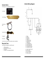
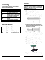
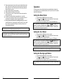
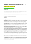
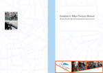
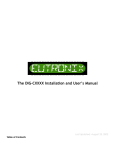
Limited Warranty
All HighTechSpeed products are warranted against defects in parts and
workmanship under normal use and correct installation for a period of one year
from the date of purchase. If any returned product is found to be defective as
described above, the product will be repaired or replaced at the discretion of
HighTechSpeed. This shall constitute the sole remedy of the purchaser and the
sole liability of HighTechSpeed to the extent permitted by law, the foregoing is
exclusive and in lieu of all other warranties or representations whether expressed
or implied, including any implied warranty of merchantability or fitness. In no
event shall HighTechSpeed be liable for special or consequential damages. This
warranty does not cover damage outside of normal use as mentioned above,
including but not limited to accident damage, fire or theft, or damage determined
to be outside of the normal use of the product. Any modifications to the product
that could interfere with it's operation in any way voids the warranty. Tampering
or removal of the "warranty void if removed" sticker will void your warranty. Any
attempt at repairing the product voids the warranty.
R1 Tail Light Integrator
Instructions for use
Congratulations
Thank you for your purchase of this HighTechSpeed product. Before
installing this product, please be sure it’s use complies with all local laws and
regulations. It is the operator’s responsibility to ensure that use of this
product does not interfere with safe vehicle operation in any way. Please be
sure to double check your installation prior to use, and familiarize yourself
with the product and its operation prior to using it on your vehicle.
Warranty Procedure
Warning
In order to obtain warranty repair or replacement, you must follow the following
procedure:
When working on your vehicle electrical system, always disconnect the
negative cable from the battery. Furthermore, when handling the circuit
board, please ensure you are not carrying a static charge. To do this, touch
something metal, like part of your bike, a door handle, etc.
1.
2.
Contact HighTechSpeed either by phone or email, and request a RMA
(return merchandise authorization) number. Our phone number is (978)
689-9477. The email address for service is
[email protected].
Send the product, postage prepaid, along with proof of purchase
including purchase date to:
HighTechSpeed
60 Ashland St., Suite C
North Andover, MA 01845
Write the RMA number clearly on the box
We will repair or replace your product, and return the unit to you (usually within
14 days). We will pay return ground shipping for domestic claims. Please include
an email address or phone number that we can contact you at should the need
arise.
Warranty return units MUST be received within 14 days after the RMA number is
issued.
Be sure to include a note in your package describing the problem in as much
detail as possible. Please give information on the problem, the symptoms, and
under what conditions you notice the problem.
8
Table of Contents
Included items.......................................................................................................2
Required Tools .....................................................................................................2
Installation.............................................................................................................3
Operation ..............................................................................................................5
Setting the Brake Pattern ..................................................................................5
Setting the Turn Pattern ....................................................................................5
Setting the Running Light Pattern .....................................................................5
Troubleshooting ....................................................................................................6
Power harness Connections .............................................................................6
Vehicle Wiring Diagram ........................................................................................7
Limited Warranty...................................................................................................8
Warranty Procedure ..........................................................................................8
Included items
Vehicle Wiring Diagram
The following items are included with your integrator kit.
1 x controller
1 x R1 LED board
1 x interconnect
cable
1 x power harness
2 x tap splice
3 x butt splice
If your kit does not include these items please contact us immediately.
Required Tools
You will need the following tools to install this product.
1.
2.
3.
4.
2
Phillips screwdriver
Sharp utility knife or box cutter
Strong pliers
Superglue or other appropriate plastic glue
1.
2.
3.
4.
5.
6.
7.
8.
9.
10.
11.
12.
Battery
Main Fuse
Main Switch
Signal Fuse
Front Brake Switch
Rear Brake Switch
Flasher Relay
Turn Signal Switch
Front Left Flasher Light
Rear Left Flasher Light
Front Right Flasher Light
Rear Right Flasher Light
A. Yellow – Brake Connection
B. Black – Ground
C. Blue – Running Light
D. Brown – Left Turn
E. Green – Right Turn
7
Installation
Troubleshooting
If you are having trouble with the unit first verify all connections are correct.
Below are some common problems and solutions.
Problem
Unit does nothing
Center light is not lit
Unable to choose a
pattern
Turn signals do not
work
Brake does not work
Resolution
Verify the blue and black wires are connected correctly.
The two interconnect wires may be reversed on the LED
board. Verify the wires are connected correctly.
For safety reasons, the ability to program the unit is
disabled once the brakes or turn signals have been used.
Turn off the bike, wait 10 seconds, then turn the bike
back on. Programming will now be enabled.
Verify the connections to the brown and green power
harness wires.
Ensure a turn signal pattern has been selected.
Verify the connection to the yellow power harness wire.
Power harness Connections
Color
Blue
Black
Yellow
Green
Brown
Description
Running/Power
Ground
Brake
Right Turn
Left Turn
Signal
+12V
Ground
+12V when brake active
+12V flashing when right turn active
+12V flashing when left turn active
Note: The control unit is not water tight and must be mounted in a dry location. If
a suitable location cannot be found, please take steps to prevent moisture from
damaging the unit. A rubber balloon with the wires going through the small end
and a rubber band around the wires is a good choice.
1.
2.
3.
4.
Connect the factory plug to the supplied power harness using the 3
supplied butt splices. The wire colors match the factory wiring, yellow to
yellow, blue to blue and black to black.
5.
Open the factory light housing. The easiest way is to take your time,
score around the base where the clear lens meets the black back. You
can also use a dremel or similar tool. When you have scored deeply all
around the base, use a vice or similar item to hold the base. Grasp and
pull the cover. If it does not easily come loose continue to score the
base.
Remove and set aside the 2 screws holding the factory light board to
the black light back. Remove the factory light board.
Thread the 2 small ends of the interconnect cable through the hole in
the black light back.
Connect the interconnect cable to the new LED board. One of the plugs
is marked with a white dot. This goes in the right side connector on the
LED board. This connector is also marked with a white dot.
6.
7.
8.
9.
6
Disconnect the negative battery terminal.
Remove your factory tail light. For instructions on how to remove the
light please consult the service manual, your local dealer, or locate
directions online.
Cut the 3 wire plug from the factory tail light between the plug and the
resistor pack as shown below. Do not cut the wire too close to the plug.
Using the factory screws, fasten the new LED board to the black light
back.
3
10. Plug the power harness into your bike using the attached factory light
plug. Connect the 2 remaining wires to the turn signals using the tap
splice connectors. The wire colors match the factory wiring, brown to
brown and green to green.
11. Plug the power harness into the controller.
12. Plug the interconnect cable into the controller.
13. Verify all wiring is correct. The power harness wire colors match the
factory wiring colors.
14. Reconnect the negative battery terminal and turn on your bike.
15. Verify the unit is operating correctly. Refer to the operation section of
this manual for instructions on how to change the patterns.
16. Once you have verified the unit is working correctly you can seal
the tail light back up. Use superglue to reattach the lens to the tail light
back. Secure the controller and wiring as necessary with zip ties or
other appropriate fasteners.
Note: If you need to remove the connectors from the controller, be sure to pull
the connectors out by the white plug and not by the wires.
Note: Once you have verified the unit is working correctly, we suggest you
put superglue on the 2 small LED board connectors inside the tail light to ensure
the wires do not come loose.
Operation
For safety reasons, the controller buttons become disabled when the brake or
turn signals are used. To enable the buttons, shut off your bike, wait 10 seconds,
then turn the bike back on.
Setting the Brake Pattern
1.
2.
3.
Press and hold the BRAKE button on the controller.
to advance to the next pattern. Press the down
Press the up arrow
to return to the previous pattern.
arrow
Once you have found a pattern you like, release the BRAKE button.
Note: A preview of your brake pattern will appear when the
and
buttons are
pressed. The pattern will disappear when the
and
buttons are released.
There is no need to operate the bike’s brake to see the pattern. Operating the
brake will disable the programming buttons.
Setting the Turn Pattern
1.
2.
3.
Press and hold the TURN button on the controller.
Press the up arrow
to advance to the next pattern. Press the down
arrow
to return to the previous pattern.
Once you have found a pattern you like, release the TURN button.
Note: A preview of your turn pattern will appear when the
and
buttons are
pressed. The pattern will disappear when the
and
buttons are released.
There is no need to operate the turn signals to see the pattern. Operating the
turn signals will disable the programming buttons.
Note: One of the turn signal patterns is “no turn signals”. This allows the
integration to be turned off by the user without rewiring.
Setting the Running Light Pattern
1.
2.
Press and hold the RUN button on the controller.
Press the up arrow
to advance to the next pattern. Press the down
arrow
to return to the previous pattern.
3. Once you have found a pattern you like, release the RUN button.
Note: Operating the brake or using the turn signals will disable the programming
buttons.
4
5