1
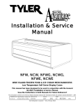
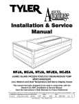
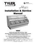
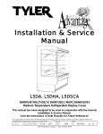
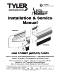
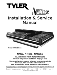
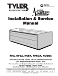
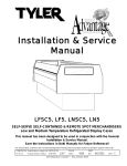
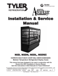
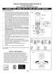
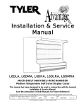
Installation & Service
Manual
L5MG
MULTI-SHELF MEAT/DELI MERCHANDISERS
Medium Temperature Self Serve Display Cases
This manual has been designed to be used in conjunction with the General
Installation & Service Manual.
Save the Instructions in Both Manuals for Future Reference!!
This merchandiser conforms to the Commercial Refrigeration Manufacturers Association Health and Sanitation standard CRS-S1-96.
PRINTED IN Specifications subject to REPLACES
IN U.S.A.
change without notice. EDITION
7/99
ISSUE
DATE
8/99
Tyler Refrigeration Corporation * Niles, Michigan 49120
PART
NO.
9027532
REV.
C
Installation & Service Manual
L5MG
CONTENTS
Page
Specifications
L5MG Specification Sheets . . . . . . . . . . . . . . . . . . . . . . . . . . . . . . . 4
Line Sizing Requirements . . . . . . . . . . . . (See General I&S Manual)
Pre-Installation Responsibilities . . . . . . . . . . . (See General I&S Manual)
Installation Procedures
Carpentry Procedures . . . . . . . . . . . . . . . . . . . . . . . . . . . . . . . . . 6
Case Pull-Up Locations . . . . . . . . . . . . . . . . . . . . . . . . . . . . . . . . 6
Plumbing Procedures . . . . . . . . . . . . . . (See General I&S Manual)
Refrigeration Procedures . . . . . . . . . . . (See General I&S Manual)
Electrical Procedures . . . . . . . . . . . . . . . . . . . . . . . . . . . . . . . . . . 6
Electrical Considerations . . . . . . . . . . . . . . . . . . . . . . . . . . . . . . . . 6
Defrost Information . . . . . . . . . . . . . . . . . . . . . . . . . . . . . . . . . . . . 7
Defrost Control Chart . . . . . . . . . . . . . . . . . . . . . . . . . . . . . . . . . 7
Installation Procedure Check Lists . . . . (See General I&S Manual)
Wiring Diagrams
L5MG Domestic & Export (50Hz) Case Circuits . . . . . . . . . . . . . . 8
Electric Defrost Circuit . . . . . . . . . . . . . . . . . . . . . . . . . . . . . . . . . 10
Optional Gas Defrost Circuit . . . . . . . . . . . . . . . . . . . . . . . . . . . . . 10
Canopy and Shelf Lighting Circuits . . . . . . . . . . . . . . . . . . . . . . . . 11
Cleaning and Sanitation . . . . . . . . . . . . . . . . . . (See General I&S Manual)
General Information
Mirror Installation . . . . . . . . . . . . . . . . . . . . . . . . . . . . . . . . . . . . . 13
Radiant Heat Information . . . . . . . . . . . . . . . . . . . . . . . . . . . . . . . 13
Display Practices . . . . . . . . . . . . . . . . . . . . . . . . . . . . . . . . . . . . . 13
Service Instructions
Preventive Maintenance . . . . . . . . . . . . (See General I&S Manual)
Light Servicing . . . . . . . . . . . . . . . . . . . . . . . . . . . . . . . . . . . . . . 14
Ballast and Lighting Locations . . . . . . . . . . . . . . . . . . . . . . . . . . . 14
Defrost Heater Replacement . . . . . . . . . . . . . . . . . . . . . . . . . . . .14
Fan Blade and Motor Replacement . . . . (See General I&S Manual)
Color Band and Bumper Replacement . (See General I&S Manual)
Anti-Sweat Replacement . . . . . . . . . . . . . . . . . . . . . . . . . . . . . . 15
Front Glass Replacement . . . . . . . . . . . . . . . . . . . . . . . . . . . . . . 15
Parts Information
Cladding and Trim Parts List . . . . . . . . . . . . . . . . . . . . . . . . . . . . 16
Operational Parts List . . . . . . . . . . . . . . . . . . . . . . . . . . . . . . . . . 19
TYLER Warranty . . . . . . . . . . . . . . . . . . . . . . . (See General I&S Manual)
The following Medium Temperature Multi-Shelf Meat and Deli Merchandiser models are covered in this manual:
MODEL
DESCRIPTION
L5MG
8’ & 12’ GLASS FRONT MULTI-SHELF MEAT/DELI MERCHANDISER
October, 1996
Page 3
L5MG
Tyler Refrigeration
SPECIFICATIONS
L5MG Multi-Shelf Meat/Deli Merchandiser Specification Sheets
Page 4
September, 1998
Installation & Service Manual
L5MG
L5MG Multi-Shelf Meat/Deli Merchandisers
September, 1998
Page 5
L5MG
Tyler Refrigeration
INSTALLATION PROCEDURES
Electrical Procedures
Carpentry Procedures
Electrical Considerations
CAUTION
Make sure all electrical connections at
components and terminal blocks are tight.
This prevents burning of electrical terminals and/or premature component failure.
NOTE
The raceway houses the electrical wiring,
components and terminal blocks for the
case. Remove the lower front cladding to
access the raceway.
Case Fan Circuit
This circuit is to be supplied by an uninterrupted, protected 120V circuit. The case fan
circuit is not cycled, except when equipped
for gas defrost. On gas defrost cases the fan
circuit is controlled by a 50/30 klixon.
NOTE
With gas defrost, the fans will not start
until the coil temperature reaches 30°F at
the fan delay thermostat.
Fluorescent Lamp Circuit
Case Pull-Up Locations
The L5MG models have four pull-ups at each
end of the case. Pull-ups A, B, C and D are
located as shown and should be installed and
tightend starting with A and finishing with D.
See “General I&S Manual” for line-up
assembly instructions.
Page 6
L5MG case lighting is supplied by T-8 electronic ballast lights. It is controlled by a light
switch in each case. The standard lighting is
2-row of T-8 canopy lights. Case lighting
options include 1-row or 2-row of 800MA HO
canopy lights and up to 4 rows of T-8 shelf
lights.
Anti-Sweat Heater Circuit
L5MG case has one anti-sweat heater in the
discharge grid. The anti-sweat heater is
wired to the hot side of the lighting power
supply so it can operate at all times.
October, 1996
Installation & Service Manual
Defrost Information
WIRING DIAGRAMS
See “General I&S Manual” for operational
descriptions for each type of defrost control.
Defrost Control Chart
Defrost
Defrost Defrosts Duration
Type
Per Day
(Min)
Off Time
4
46
Electric
4
36
Gas
4
12-15
L5MG
Term.
Temp.
50°F
50°F
55°F
ELECTRICIAN NOTE - OVERCURRENT
PROTECTION
120V circuits should be protected by 15 or 20 Amp
devices per the requirements noted on the cabinet
nameplate or the National Electrical Code, Canadian
Electrical Code - Part 1, Section 28. 208V defrost
circuits employ No. 12 AWG field wire leads for field
connections. On remote cases intended for end to
end line-ups, bonding for ground may rely upon the
pull-up bolts.
The following wiring diagrams on pages 8
thru 11 will cover the L5MG case circuits,
electric and gas defrost circuits and the lighting wiring circuits.
E = Electric Defrost
G = Gas Defrost (Fan Delay)
NOTE
The termination thermostat for gas defrost
is located on the bypass check valve at the
left end of the evaporator coil.
All klixons are located on the right end of the
evaporator coil. The diagram shows the location for each defrost type that uses a klixon.
CAUTION
If electronic sensors are used in place of
the klixons, the sensors must be located in
the same location as the klixons for that
defrost type. Any other locations will
effect the refrigeration efficiency of the
case.
July, 1999
Page 7
Page 8
January, 1997
July, 1999
Page 9
Page 10
January, 1997
July, 1999
Page 11
L5MG
Tyler Refrigeration
Electric Defrost Circuit
Optional Gas Defrost Circuit
NOTE
Page 12
:
ALL CASES MUST BE GROUNDED
July, 1999
Installation & Service Manual
L5MG
Canopy and Shelf Lighting Circuits (8’ Cases)
January, 1997
Page 13
L5MG
Tyler Refrigeration
Canopy and Shelf Lighting Circuits (12’ Cases)
Page 14
January, 1997
Installation & Service Manual
GENERAL INFORMATION
Mirror Installation
When installing mirrors you must be aware
that on longer line-ups it is possible to end up
with a gap at the end of the line-up. To help
prevent this, leave a gap at the starting end
that can be covered by the stainless steel
trim. Additional mirror positioning adjustments may be required to make sure the
gaps at each end of the line-up don’t show
when the stainless steel trim is in place. Also
make sure all mirrors have a good tight seal
between each mirror.
Radiant Heat Information
L5MG
center of a piece of meat compared with one
in the air stream quickly confirms this fact.
Another fact is that the surface temperature of
the meat will be higher than the center temperature due to radiant heat. TYLER’s ongoing research identifies sources of radiant heat
and accurately measures and records it.
These charts were developed from the information gathered during this research. Two
major sources of radiant heat are from display lights and ceiling surfaces. Additional
heat sources come from bad display practices which either overload the case with
product or allow voids in the product display.
Poor display practices impair the efficiency of
the refrigeration, adding to the surface temperature of the meat. Bacteria and molds
grow when surface temperatures rise above
45°F. This prematurely discolors displayed
meats and causes unnecessary meat department losses.
Radiant Heat Measurement
Place two accurate dial thermometers side by
side in a case. Cover one of the thermometer
stems with black friction tape. The temperature difference is the approximate amount of
radiant heat. A change in display lighting or
a reduction of high ceiling temperatures (over
80°F) could reduce the radiant heat in the
case.
Display Practices
A wide temperature range is shown for each
type of lighting. This data does not show all
situations. Many situations will have higher
package warm-up figures than indicated.
It is generally known that the temperature of
displayed meat in refrigerated cases will run
higher than the circulated air temperature of
the cases. A dial thermostat stuck into the
January, 1997
Encourage butchers
to maintain all meat
below the case load
lines and to eliminate
product voids. Case
screens could be
covered in some instances to keep the refrigerated air over the display.
CAUTION
The quality damage done to meat products
by high temperatures and/or contamination
during delivery, cooler storage, cutting and
wrapping cannot be repaired by placing
the products into properly operating display cases.
Page 15
L5MG
Tyler Refrigeration
SERVICE INSTRUCTIONS
Light Servicing
See “General I&S Manual” for T-8 and
800MA lamp, ballast , fan blade and motor,
and color band and bumper replacement
instructions.
Ballast and Lighting Locations
1. Remove bottom trays (1) from case (2).
All light ballasts are located under the canopy
and mounted on the top of the canopy light
fixture. This includes remote ballasts for
optional shelf lights. The canopy light(s) are
under the canopy light fixture in the top of the
case. The optional shelf lights are mounted
in separate light fixtures under the front of
each shelf section.
Defrost Heater Replacement
WARNING
Always shut off electricity to case before
replacing a defrost heater. Automatic
cycling of fans or electrical power to wire
ends could cause personal injury and/or
death.
Page 16
2. Unclip and lift up fan plenum (3).
3. Disconnect and remove defrost heater (4)
from mounting clips (5) and case (2).
4. Install new defrost heater (4) in reverse
order.
5. Restore electrical power to case.
October, 1996
Installation & Service Manual
Anti-Sweat Replacement
L5MG
Front Glass Replacement
L5MG cases have one anti-sweat heater in
the discharge air grid. All anti-sweat heaters
are wires that run the length of the above
mentioned components. Use the following
instructions to replace an anti-sweat heater.
WARNING
Shut off or disconnect power supply to
case before changing an anti-sweat.
Electrical power from wire ends could
damage other components and/or cause
personal injury or death.
1. Remove screw (1), screw nut (2), glass
joint trim (3) and glass joint backer (4)
from both joints of the broken glass.
2. Remove glass trim rail (6) from top of
glass (5).
1. Expose the full length of the defective
anti-sweat wire (1) in the case (2).
2. Disconnect or cut the defective anti-sweat
wire (1) from the case wires (3).
3. Remove the aluminum tape (4) and defective anti-sweat wire (1) from the case (2).
4. Position new anti-sweat wire (1) in case
(2) and secure with new aluminum tape
(4).
5. Connect or splice the new anti-sweat wire
(1) to case wires (3).
3. Loosen rear retainer (7) and remove broken glass from glass retainer assembly
(8).
4. Apply sealant tape (9) to top and bottom
edge of new glass (5).
5. Position new glass (5) in glass retainer
assembly (8) and secure by tightening
rear retainer (7).
6. Install glass trim rail (6) over top edge of
new glass (5).
7. Install glass joint backer (4), glass joint
trim (3) with screw (1) and screw nut (2)
over both joint areas of the glass (5).
6. Replace all components that were
removed to expose the anti-sweat wire
(1).
7. Restore electrical power to case.
October, 1996
Page 17
L5MG
Tyler Refrigeration
PARTS INFORMATION
Cladding and Trim Parts List
Item Description
L5MG
8’
12’
5183536(4)
5183536(4)
9026103
9026103
5183536(5)
5183536(7)
1
Screw (per cover)
2
End Cover (1 per side)
3
Screw
4
Close-off, Hood
9026069
9026070
5
Canopy Backer, Painted
9025983
9025983
6
Canopy Hood, Painted
9025223
9025224
7
Screw
5183536(8)
5183536(10)
8
Bumper Retainer
9025058
9025061
9
Color Band, Painted
9020971
9020972
10
Color Band Backer, Painted
9025982
9025982
11
Bumper
color per order
12
Bumper Backer
color per order
Bumper End Trim
(per patch end/not shown)
color per order
13
Upr. Front Cladding Support
9026387
9026388
14
Shoulder Screw
9025833(14)
9025833(18)
15
Screw
5183536(10)
5183536(14)
16
Front Cladding, Painted
9026551
9026552
17
Rivet
5104702(6)
5104702(6)
18
Kickplate
19
Kickplate Support Assy.
9042340(3)
9042340(4)
20
Shoulder Screw
9025833(8)
9025833(8)
21
LH End Close-off, Painted
9022459
9022459
RH End Close-off, Painted
9022466
9022466
5222637(6)
5222637(6)
9026101
9026102
5183536(5)
5183536(7)
9025959
9025959
Binding Screw
22
Raceway
23
Screw
24
Horizontal Joint Trim
Page 18
color per order
August, 1999
Installation & Service Manual
L5MG
July, 1999
Page 19
L5MG
Tyler Refrigeration
Front Glass Trim Parts
Item Description
L5MG
8’
12’
1
Glass Joint Backer
9026404
9026404
2
Top Glass Trim Rail
9026561
9026562
3
Glass Joint Trim
9026907
9026907
4
Binder Screw
5222627
5222627
Page 20
July, 1999
Installation & Service Manual
L5MG
Operational Parts List
Case Usage
Electrical Circuit
Domestic
Export
115 Volt 60 Hertz
220 Volt 50 Hertz
Case Size
8’
12’
8’
12’
Fan Motor
5235088
9 Watt
5235088
9 Watt
5223696
ESP
5223696
ESP
Fan Motor Brackets
5235087
5235087
5205112
5205112
Fan Blades (8.75” 25° 5B)
5984399
5984399
5984399
5984399
T-8 Ballast (canopy)
5966635
5991030
9028439
9028438
Opt. 800MA T-12 Ballast (can./1-row)
5049140
5049140
5024859
5024859
Opt. 800MA T-12 Ballast (can./2-row)
5204796
5049140
5024859
5024859
Opt. T-8 Ballast (shelf)
5966635
5966635
9028439
9028439
T-8 Lampholder (canopy)
5232279
5232279
5232279
5232279
T-8 Lampholder (shelf)
5092414
5092414
5092414
5092414
Opt. 800MA Lampholder (telescoping)
5614628
5614628
5614628
5614628
Opt. 800MA Lampholder (stationary)
5614629
5614629
5614629
5614629
Light Switch (SPST)
5193982
5193982
5193982
5193982
Anti-Sweat Heater Wire (canopy)
5124216
5124217
5081147
5081148
Opt. Elec. Def. Heater
5124521
5124522
5124521
5124522
Opt. Elec. Def. Limit Switch
5125211
5125211
5125211
5125211
Opt. Gas Def. Fan Delay Switch
9023503
9023503
9023503
9023503
Opt. Gas Def. Term. T’stat
9023508
9023508
9023508
9023508
For information on operational parts not listed above contact the TYLER Service Parts
Department.
July, 1999
Page 21