1
FL-1-BFM:TEMPLATE
12/4/08
10:59 AM
Page 2
BFM WIRING
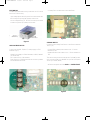
The BFM polycarbonate housing comes with 10 PG conduit
knockouts in the housing.
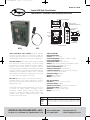
• A 1-Amp fuse is located next to the transformer.
• High voltage inputs above 24 volt AC should be routed into
the housing through the 3/4˝ (20mm) conduit hole.
• All Low voltage wiring (TTL, RS232, and sensor) should be
routed through the 1/2˝ (14mm) conduit hole.
3/4˝ HIGH
VOLTAGE INPUT
1/2˝ LOW
VOLTAGE INPUT
Figure 3
Figure 1
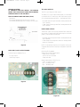
HIGH VOLTAGE INPUTS
Connect the 120VAC, 50/60 HZ, 1 Amp supply on TB2
terminals (Fig. 2):
• 120VAC (Hot) supply to 117VAC terminal (or 12VDC, 240VAC
per the model)
• AC Common to AC COM terminal
• Earth-Ground to E GND terminal. Must connect to prevent
accidental electrical shock.
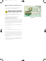
SENSOR INPUTS
Connect the low voltage Flow Sensor to the Sensor terminals
TB1 (Fig. 4):
• Positive RED (or White) sensor lead to the “+” Sensor
terminal on TB1.
• Negative BLACK sensor lead to the “-” Sensor terminal on
TB1.
The sensor wiring should be a minimum of 18 AWG stranded 2-conductor cable. Use 18 AWG for up to 500´ (155m) and
16 GA up to 2000' (620m).
• All Sensor wire splices must be SOLID and WATER TIGHT.
Figure 2
Figure 4