1
FL-1-BFM:TEMPLATE
12/4/08
10:59 AM
Page 6
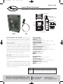
SENSITIVITY RANGE ADJUSTMENT AND CALIBRATION
The BFM has (3) three sensitivity range inputs. Select the range
to get the desired sensitivity for the application.
WARNING: TO AVOID ELECTRICAL SHOCK
DISCONNECT AC SUPPLY VOLTAGE BEFORE
ADDING OR REMOVING JUMPERS ON TB1.
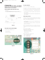
• Minimum (low) range: Install jumper J2 (only)
• Medium range: No jumpers installed (as shipped from
factory)
• Maximum (high) range: Install jumper J1 (only)
ADJUSTING THE SENSITIVITY RANGE:
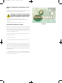
NOTE: The sensitivity range is factory preset to the Medium
range (no jumpers installed). Verify that the supply voltage and
the flow sensor are wired and installed correctly prior to testing (Fig. 14). After selecting proper sensitivity range, proceed
to the next calibration section.
1. With no material flowing, turn the Sensitivity adjustment to
full clockwise position:
• RED LED will turn on.
2. Start the material flowing at the full rate you wish to monitor:
• If the GREEN LED turns on, then turn the Sensitivity adjustment fully counterclockwise. If that causes the RED LED to
turn on then the correct sensitivity range is selected. If that
does not cause the RED LED to turn on (Green stays lit) then
install jumper J2 (Minimum range) and repeat the test beginning with step #1.
• If the GREEN LED does not turn on when material is flowing, then install jumper J2 (Maximum range) and repeat the
test beginning with step #1.
Figure 14