1
FL-1-BFM:TEMPLATE
12/4/08
10:59 AM
Page 3
RELAY AND LOW LEVEL LOGIC WIRING
SIDE VIEW
FRONT VIEW
See those sections later in this manual.
BFM
SENSOR
SENSOR INSTALLATION
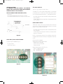
The BFS-1 sensor is in very a rugged polymer housing with a
sealed 6´ cable pigtail (Fig. 5):
• Red/Black = Positive
• White/Black = Negative (this is electrically connected to the
metal sensor stud)
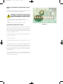
NOTE: PILOT HOLES
ARE DRILLED INTO
FLAT SURFACE AND
MOUNTED WITH
PORPER HARDWARE.
BFM
SENSOR
Figure 6
MOUNTING TO A ROUND OR NON-FLAT SURFACE:
(FIG. 7)
BFM SENSOR
• Using strapping (such as heavy duty wire-ties) or clamps to
secure the sensor housing to the pipe so the metal sensing
stud makes firm contact with the surface.
BLACK LEAD
RED/WHITE LEAD
SIDE VIEW
FRONT VIEW
Figure 5
MOUNTING PROCEDURES FOR SENSOR:
The BFS-1 Sensor can be screwed, clamped or strapped in
place and is able to detect flow through most sheet metal.
• Clean the surface area where the sensor is to be installed.
The surface should not have any buildup or scale but does
be perfectly clean.
• The sensor stud located at the bottom of the sensor
housing must make solid contact with the surface of the
pipe to be monitored.
MOUNTING TO A FLAT SURFACE:
Refer to the mounting holes located at each end of sensor
housing (Fig. 6).
• Mark mounting holes.
• Drill pilot holes for mounting screws.
• Screw sensor housing to flat surface.
BFM
SENSOR
NOTE: STRAPS
OR CLAMPS
ARE USED FOR
MOUNTING TO
NON-FLAT
SURFACE
Figure 7
BFM
SENSOR