1
12
Auto Engine Repair
Combustion
pressure
Ring
tension
Compression
ring
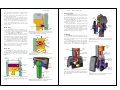
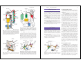
The piston rings fit into grooves machined into the
sides of the piston. These rings keep combustion pressure
from entering the crankcase and engine oil from entering
the combustion chamber. Look at Figure 1-4.
The compression rings seal the clearance between
the block and piston. They are normally the two upper
piston rings. Their job is to contain the pressure formed in
the combustion chamber, Figure 1-5. Without compression rings, pressure would blow past the outside diameter
of the piston and into the lower area of the engine block.
The oil ring fits into the lowest groove in the piston. It
is designed to scrape excess oil from the cylinder wall to
keep it from being burned in the combustion chamber,
Figure 1-6. If oil enters the area above the piston and
burns, blue smoke blows out of the tailpipe.
Review of Engine Operation
13
Connecting Rod
fuel, which results in expanding gas inside the cylinder.
The piston transfers the pressure of combustion to the
piston pin, connecting rod, and crankshaft. It also holds
the piston rings and piston pin.
During engine operation, the piston slides up and
down in the cylinder at tremendous speeds. At a vehicle
speed of about 55 mph (88 km/h), the piston can accelerate from zero to 60 miles an hour and then back to
zero in one movement from top to bottom in the
cylinder. This places tremendous stress on the piston and
its related parts.
Piston Rings
Chapter 1
Cylinder
wall
Piston
Figure 1-5. The compression rings use combustion pressure to
help seal against the cylinder wall. This keeps pressure in the
combustion chamber and out of the crankcase.
Cylinder wall
Piston
Ring
groove
Oil control
ring
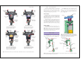
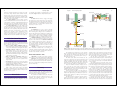
The connecting rod transfers the force of the piston to
the crankshaft. It is fastened to the piston pin at the top and
the crankshaft at the bottom. It also causes piston movement on nonpower-producing events (up and down piston
movements). See Figure 1-8.
The small, top end of the connecting rod has a hole
machined in it for the piston pin. The top of the rod
extends inside of the piston.
The big, bottom end of the connecting rod fits around
the crankshaft journal. It has a removable cap that allows
the installation and removal of the rod-piston assembly.
Special rod bolts and nuts hold the cap in place.
As discussed in later chapters, bushings are normally
installed in the small end of the rod. Rod bearings are
installed in the big end of the connecting rod.
Crankshaft
A piston pin, also called a wrist pin, allows the connecting rod to swing back and forth inside the piston. The
pin fits through a hole machined in the piston and through
a hole in the upper end of the connecting rod. Refer to
Figure 1-7.
Piston
clearance
Piston
clearance
Oil film
Oil to crankcase
Figure 1-6. Oil rings act as a scraper to keep oil out of the combustion chamber. (Deere & Co.)
Piston
head
Piston
diameter
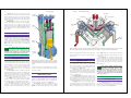
Figure 1-9. The crankshaft takes the reciprocating motion of
the piston and produces rotary motion for vehicle’s drive train
and accessory system.
Connecting
rod I-beam
Big end
for rod
bearing
Piston at
bottom dead
center
Rod bolt
Rod cap
Rod and
its crankshaft
journal up
Piston
pin
Compression
rings
Piston
Piston
pin bore
Oil ring
Figure 1-4. The clearance between the piston and cylinder
allows the piston to move freely in the cylinder. Rings seal the
clearance.
Counterweight
Piston
pin
Rod nut
Piston pin
Snout
Piston at
top dead
center
Small end
Ringlands
Flywheel
flange
Main
journals
The crankshaft converts the up and down (reciprocating) movement of the connecting rod and piston into rotary
motion. The rotary motion is used to power gears, chains,
belts, and the drive train.
The crankshaft fits into the main bore of the engine
block, as shown in Figure 1-9. It mounts on the main bearings and is free to spin inside the block. The connecting
rods are attached to the crankshaft journals. Figure 1-10
Escaping
oil
Piston Pin
Rod
journal
Connecting
rod
Swinging action
Figure 1-7. The piston pin fits into a hole bored in the piston.
The pin attaches the piston to the connecting rod.
Figure 1-8. The connecting rod links the piston and crankshaft
together. The large end has a removable cap that allows the rod
to be bolted around the crankshaft journal. The small end has a
hole for the piston pin.
Rod and its
crankshaft
journal down
Figure 1-10. Note how the crankshaft changes the reciprocating motion of the piston into rotary motion.