1
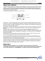
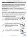
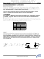
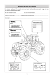
WARNING
The location and orientation of the cooling tower can affect the safety of those
responsible for installing, servicing or reparing the cooling tower. Since SPX does not
dictate or determine where the tower is located or how iti is oriented, SPX is not
responsible for addressing the safety issues that are affected by the tower's location
location and orientation. The following safety issues should be considered by those
responsible for designing and maintaining the tower installation. Failure to consider and
address these issues may result in substantial personal injury or death to those
installing, servicing or repairing the cooling tower.
* Access to and from the fan deck.
* Access to and from maintenance access doors.
* Access for cleaning and other service.
* Potential access problems due to obstructions surrounding the tower.
* The possible need for safety cages around ladders.
These are only some of the safety issues that may arise in the design process. SPX
strongly recommends that you consult a safety engineer to be sure that all safety
considerations have been addressed.
CONFIDENTIAL - The contents of this document are confidential and constitute the
exclusive property of SPX Cooling Technologies and is intended for use in the
construction (contractor) and maintenance (owner) of this cooling tower. This document
and its contents may not be made public in any manner, distributed or loaned to others,
or repoduced or copied either in whole or part without prior written consent of SPX
Cooling Technologies.
This page intentionally left blank
Contents
NC8400
GETTING STARTED
ABOUT THIS MANUAL
MEASUREMENT SYSTEM
TOOLS AND SUPPLIES
JOINT SEALING INSTRUCTIONS
A FEW WORDS ABOUT FASTENERS
GENERAL DECAL INSTRUCTIONS
STANDARD FIELD DETAILS
MODULE CONNECTION DETAILS (NC8411 THRU NC 8414 ONLY)
FAN GUARD
VELOCITY RECOVERY STACK
BASIC INLET PIPING
INLET PIPING WITH OPTIONAL HC VALVES
SINGLE INLET PIPING OPTION
OVERFLOW & DRAIN
FIELD INSTALLED OPTIONS
SUMP
BOTTOM OUTLET
BOTTOM OUTLET SCREEN
SCREEN WITH ANTI-VORTEX PLATE
FLUME
WEIR GATE
FLOAT VALVE FLOAT
STANDPIPE FLOAT VALVE
ELECTRIC BASIN HEATERS
EXTERNAL VIBRATION SWITCH
MOTOR OUTSIDE AIRSTREAM (MOA)
FIELD INSTALLED MOTOR
NC8400 Field Install-1 PAGE 3 OF 4
This page intentionally left blank
Getting Started
PRELIMINARY
NC8400
ABOUT THIS MANUAL
To obtain maximum efficiency, it is strongly recommended that this entire manual be read before starting
assembly. This assembly manual illustrates the field installation of standard and optional items that your
tower may have. Due to shipping limitations these items can not be installed in the factory. Review all
manuals, drawings, and bills of material prior to assembly. Contact your SPX Cooling Technologies sales
representative should questions arise.
All steel parts are tagged for identification, as shown below.
Find Number: This is a three digit alpha/numeric number that ties everything together. Used throughout
this manual, in the text, it's the number in bol type M35, in the figures, it's the number within the circle. It is
also the first column in the BILL OF MATERIAL. In the bill of material, all tower hardware components are
listed in numerical order by this number.
Item Number: This number is used by SPX to manufacture and inventory the components of your cooling
tower. Give this number to your SPX sales representative if an item is missing or a replacement item is
required.
Drawing Number: (Reference only) This is the number of the drawing used to fabricate this item.
Description: (Reference Only) All steel parts begin with SHEET or ASSEMBLY followed by the size of the
sheet used to fabricate the item or a description of the assembly. Your tower may have a few fiberglass
items which begin GRP.
Stainless Steel: This indicates when an item has been made from stainless steel. If the item is made
from the standard galvanized material this will not be printed on the tag.
Bills of material (BOM) are separate from drawings and this manual. At the top of each bill there is a
Drawing Number and the drawing description which indicates if the items on that bill will be installed per
this assembly manual or per a special installation drawing.
The find number, item number, description and quantity of items are all cross referenced on the bill of the
material. If a number is missing or hard to read, check the illustrations in this assembly manual first and
then the bill of material to see if you can find it. As the tower is prepared for assembly, the quantities of
each item should be checked against the bill of material.
NEED HELP!
If anything is missing, damaged, or you need help of any kind, contact your SPX Cooling
Technologies Representative as soon as possible. If you need help determining the representative
in your area, please call us at 1-800-4MARLEY, or check the internet at www.spxcooling.com
NC8400 Field Install-2 PAGE 1 OF 8
Getting Started
PRELIMINARY
NC8400
MEASUREMENT SYSTEM
The manual uses both, the English System and Metric System of measurement. All units are in
millimeters. Fasteners are denoted in both the English and metric systems. Fasteners are supplied in
conformance with the metric system standard unless otherwise noted in the tower bills of material.
TOOLS AND SUPPLIES
Hoist: 2500 (1140kg) pound capacity. For hoisting of motor on towers with field installed motors or MOA.
1/2" electric drill and bit set.
Socket wrench set: Tower mainly uses 13mm, 19mm & 30mm sockets. Have more than one if
possible.
Combination wrenches: Mainly 13mm up to 30mm. Adjustable wrenches are OK but not
recommended.
Screwdrivers:
Torque wrench: 150 ft lb (203 N-m) capacity.
Caulking guns: Required for application of sealant.
Pipe Wrenches:
Small and large drift pins: (alignment tools) These are extremely important to help line up all the holes.
You should have more than one.
Allen wrenches:
Protractor level: For setting fand blade pitch.
Dial Indicator kit: Marley Item No. 115311M. For drive shaft alignment. Needed for motor outside
airstream option only.
Scaffolding, portable stairs or other means of temporary access and support.
Impact wrenches (electric or pneumatic) with standard and deep sockets: used to tighten all
hardware.
Acetone solvent: About a gallon (4 liters) and clean cotton rags.
Wear protective clothing, gloves, nonslip footwear, hard hat and safety glasses. Fluid Coolers are
constructed of steel and could have burrs that can cause cuts. The surface of the steel could be slick.
Protection from thrown, or falling objects should be used at all times around a construction site.
NC8400 Field Install-2 PAGE 2 OF 8
Getting Started
PRELIMINARY
NC8400
JOINT SEALING INSTRUCTIONS
Surface preparation instructions:
The following information covering surface preparation applies to all sealed joints whether sealer Z11 or
strip sealer Z12 or Z13 is bein used. Years of experience has shown the instructions on surface
preparation and sealing details do result in watertight joints. Inadequate attention to these details will
result in joints that leak.
Do not apply either sealer if temperature is below 40° Fahrenheit (5 ° Celcius).
All flanges are to be straight. Rework kinks or bends that exist. Clean surfaces being sealed with acetone.
If cloth is used, it must always be clean and dry. Excercise caution in using solvents, always read
labels and instructions. Care should be taken not to wipe dirt or oil onto the cleaned surface from
adjacent uncleaned area. Mating surfaces to be sealed must be kept clean and dry prior to assembly. No
water, grease or dirt should contaminate cleaned area. Note that stainless steel requires a larger area to
be cleaned because oil will recontaminate surfaces quickly. Oil will migrate through punched holes and
around sheared edges.
Application instructions for Sealer Z11 (Type A, B, & C seals):
Sealer Z11 comes in a 1/12th gallon (315ml) cartridge and is applied using a standard caulking gun. Apply
sealer to the unassembled parts. The typical joint sealing details shown on this page and the following
page are referenced throughout this manual. Care should be taken to fill voids and gaps at joints. After
parts have been assembled, trowel excess sealant over joint, taking care to force sealant back into joint,
and not out of joint. Do not use solvent to aid in applying sealer as solvent adversely affects bonding of
sealant to metal. Care should be taken to avoid leaving holes or air bubbles in sealant.
Do not subject sealed joints to waterloading for 48 hours at temperatures of 70° Fahrenheit (21° Celci us)
and above. Lower temperature will require a longer cure time.
"A"
"B"
WATER SIDE
OF JOINT
This symbol is used throughout the manual to indicate the
locations where sealer Z11 is required. The "A" refers to a
"Type 'A' Seal" which is a 3/8" (10mm) diameter bead of
sealer Z11 laid along the centerline of a row of holes
curving over each hole as it passes. Reference detail at
the right.
FASTENER
HOLE
This symbol is used throughout the manual to indicate the
locations where sealer Z11 is required. The "B" refers to a
"Type 'B' Seal" which is a 3/8" (10mm) diameter bead of
sealer Z11 laid along the centerline of a row of holes
curving completely around each hole as it passes.
Reference detail at the right.
FASTENER
HOLE
Z11 TUBE SEALER
3/8" [10mm] BEAD
TYPE A SEAL
Z11 TUBE SEALER
3/8" [10mm] BEAD
TYPE B SEAL
"C"
FASTENER
HOLE
This symbol is used throughout the manual to indicate the
locations where sealer Z11 is required. The "C" refers to a
"Type 'C' Seal" which is a 3/8" (10mm) diameter bead of
sealer Z11 laid completely around each hole in a row of
holes. Reference detail at the right.
Z11
TUBE SEALER
3/8" [10mm] BEAD
TYPE C SEAL
NC8400 Field Install-2 PAGE 3 OF 8
Getting Started
PRELIMINARY
NC8400
Application instructions for Strip Sealer Z12 & Z13 (Type D, E & F seals):
Strip sealer is supplied in 1/2" (12mm) Z13 and 1" (25mm) Z12 widths. It is intended that the 1" (25mm)
wide sealer be used unless otherwise noted.
Apply continuous pieces of strip sealer to the unassembled parts. Do not splice pieces except where
turning a corner. Cut with a sharp instrument, do not stretch or tear.
Gaps at joints and corners can be filled by stretching a piece of strip sealer to obtain the proper thickness.
Then work it into the joint to fill the gap and create an even surface.
After parts are set together, use a drift pin or other pointed object to puncture sealer at each fastener hole,
where required.
FASTENER HOLE
"D"
This symbol is used throughout the manual to
indicate the locations where a single layer of strip
sealer Z12 or Z13 is required. Reference detail at the
right.
Z12 or Z13
TYPE D SEAL
FASTENER HOLE
WATER SIDE
OF JOINT
"E"
This symbol is used on collection basin joints to
indicate the locations where two layers of strip sealer
are required. Align bottom edge of strip sealer Z13
with top edge of bolt holes. Align top edge of strip
sealer Z12 with bottom edge of bolt holes. Reference
detail at the right.
Z13
Z12
TYPE E SEAL
FASTENER
HOLE
"F"
This symbol is used on distribution basin joints to
indicate the locations where two layers of strip sealer
are required. Align bottom edge of first strip sealer
Z13 with top edge of bolt holes. Align top edge of
second strip sealer Z13 with bottom edge of bolt
holes. Reference detail at the right.
Z13
Z12
TYPE F SEAL
NC8400 Field Install-2 PAGE 4 OF 8
Getting Started
PRELIMINARY
NC8400
A FEW WORDS ABOUT FASTENERS
Stainless Steel Fasteners:
Stainless steel fasteners are prone to galling. This is when you notice a sudden increase in the force
needed to turn a nut before parts are clamped. Apply anti-seize compound to the threads of the bolt
before installing the nut. If a nut does not easily spin on a bolt, do not try to force it. Chances are it will
seize. Some extra hardware is included to replace problem hardware.
This manual depicts flanged-head fasteners. On stainless steel towers these connection points will
consist of a regular hex-head bolt and two washers in place of the flange-head bolt.
Tap Screw Repair:
During installation of tap screws in sheet metal parts, tap screws may strip, not allowing the screw to be
fully tightened. if this occurs, place a 3/8" [10mm] nut on the back side of the tap screw and tighten.
Torque requirements:
The idealized standard fastener torque values for galvanized and stainless steel fasteners are shown in
the table below. These values may vary in actual practice. Note that the values shown for stainless steel
fasteners are based on the fasteners being lubricated with anti-seize compound.
FASTENER TORQUE
BOLT
DIAMETER
8mm
10mm
12mm
16mm
20mm
FASTENER TORQUE
FOOT-LBS. (NEWTON-METERS)
GALVANIZED * STAINLESS STEEL
20 (27.1)
20 (27.1)
20 (27.1)
20 (27.1)
45 (61)
27 (37)
90 (122)
44 (60)
150 (203)
74 (100)
* Values based on fasteners lubricated with
anti-seize compund. (Stainless steel only)
Loctite®
Critical structural and mechanical attachments require extra protection against the nuts vibrating loose
during tower operation. This is accomplished on galvanized fasteners by applying Loctite, Z05, thread
locking compound to the exposed threads of a bolt after the nut has been installed and tightened. Bolts
should be installed with the threaded end up or horizontally. Reference details below. On stainless steel
fasteners the use of anti-seize compound makes the use of loctite ineffective. Therefore in these critical
areas with stainless steel fasteners, self-locking nuts have been substituted for the standard nuts and
loctite will not be used.
This symbol is used throughout the manual
to indicate the locations where Loctite Z05
is required. Reference details at the right.
Z05
Z05
Typical bolted attachment with threaded
end of bolt up, or installed horizontally
NC8400 Field Install-2 PAGE 5 OF 8
Getting Started
PRELIMINARY
NC8400
GENERAL DECAL INSTRUCTIONS
Decals are an important part of the tower assembly. Decals provide instructions, identifications, cautions
and warnings deemed necessary for proper operation and safety.
Surface Preparation
Surface must be clean and dry. Oil and dirt may be removed with solvent (such as acetone) or
commercial detergent. Wash the area with warm water and dry with a lint-free cloth. Ultimate adhesion
will occur 24-28 hours after application should not be undertaken if temperature is below 35 degrees
Fahrenheit, or if humidity is greater than 95%.
General Application Instructions
Peel off backing paper, taking care to avoid dirt contamination of the exposed adhesive. Carefully apply
decal to the desired location with light pressure to avoid distortion of the vinyl. Once in position, smooth
out with a towel. If air bubbles occur, puncture with a pin and smooth down with a towel. The finished
decal should be completely flat.
NC8400 Field Install-2 PAGE 6 OF 8
Getting Started
PRELIMINARY
NOTES
NC8400 Field Install-2 PAGE 7 OF 8
NC8400
Getting Started
PRELIMINARY
This page intentionally left blank
NC8400 Field Install-2 PAGE 8 OF 8
NC8400
PRELIMINARY
Module Connection Details
MODULE CONNECTION DETAILS
NC8411 thru NC8414 only
Before top module is hoisted into place on bottom module, clean any
dirt and debris from the underside of the top module skid sides and
beams. Remove shipping guards from bottom of top module. After top
module is in place the modules may be connected near louver
columns as shown in Figure 1, or inside tower on eliminator face per
Figure 2.
NC8400
FIND NO.
DESCRIPTION
VN3
BOLT, HF 20MM X 45MM
W05
WASHER, LOCK, M20
X64
NUT, HF M20
Top Module
BEFORE HOISTING!
Remove shipping guards from
bottom of top module.
VN3
W05
Clean any dirt and debris
from the underside of the
top module skid & beams
before hoisting into place.
BEFORE HOISTING!
Make sure seal strips are in place along
cased face girts and on eliminator support
beams of bottom module. A 2" (51mm) gap
will exist in seal strip adjacent to fill. If
problems exist, contact SPX representative.
Bottom Module
X64
VN3
Figure 1
W05
Clean any dirt and debris
from the underside of the
top module skid & beams
before hoisting into place.
BEFORE HOISTING!
Make sure seal strips are in place along
cased face girts and on eliminator support
beams of bottom module. If problems exist,
contact SPX representative.
X64
Figure 2
NC8400 Field Install - Module Connection PAGE 1 OF 1
PRELIMINARY
Fan Guard
NC8400
D32
D34
B
FAN DECK
A
X60
X60
N97
W24
VP1 Pre-installed
at factory
X60
VP1
DETAIL B
FAN GUARD
A single piece fan guard is provided on models NC8401
thru NC8403, Models NC 8405 thru NC8414 use a two
piece fan guard and require guard splice hardware. On
models with a single piece fan guard, position guard
D34 over cylinder and raise center to align holes in fan
cylinder. On models with a two piece fan guard, guard
D32 is installed first and a splice clip N97 is used to
retain guard D34.
DETAIL A
FIND NO.
DESCRIPTION
VP1
BOLT, HF 8MM X 25MM
W24
WASHER, FLAT, M8
X60
NUT, HF M8
NC8400 Field Install - Fan Guard PAGE 1 OF 1
PRELIMINARY
Velocity Recovery Stack
NC8400
Pre-installed
X60 at factory
W24
X61
Pre-installed
at factory
VP1
VP3
Pre-installed
at factory
D31 Typical
Fan deck
VELOCITY RECOVERY STACK
On models with a velocity recovery stack, install
fiberglass cylinder segments D31 per Figure 1 on top of
lower cylinder that extends down from deck. Segments
are to straddle tower centerline. Installation hardware
for the cylinder segments has been pre-installed at the
factory and must be removed prior to cylinder
installation. Fan guard is not required on these models.
FIND NO.
DESCRIPTION
VP1
BOLT, HF 8MM X 40MM
VP3
BOLT, HF 10MM X 25MM
W24
WASHER, FLAT, M8
X60
NUT, HF M8
X61
NUT, HF M10
NC8400 Field Install - VR Stacks PAGE 1 OF 1
PRELIMINARY
Basic Inlet Piping
NC8400
BASIC INLET PIPING
If tower is not using the optional HC valves, inlet piping is attached directly to the
distribution basin, see Figure 1. Note that inlet piping and fasteners are supplied
by others.
Inlet piping and fasteners
Supplied by others. Fasteners
to be the same material as the
distribution basin.
N45
Distribution basin
Center section of inlet flume
may be removed if access
for attaching inlet piping is
required. Reinstall flume
after inlet piping is secure.
Piping, supports, design
of piping and supports,
and restraint of lateral
piping loads is the
reponsibility of others.
Figure 1
NC8400 Field Install - Basic Inlet Piping PAGE 1 OF 1
HC Valves
PRELIMINARY
NC8400
INLET PIPING WITH OPTIONAL HC VALVES
If HC valves N40 are to be installed, attach as shown. A full face
gasket N45 is used between valve and distribution basin, and a ring
gasket N39 is used between valve and inlet piping. Valve may be
rotated 90° or 180° if desired.
Inlet piping
supplied by others
6" & 8" dia. V35
valves
or
10" dia.
V42
valve
6" & 8" dia. X04
valves
or
10" dia. X06
valve
N39
Ring gasket
without bolt circle
N40
Center section of intet
flume may be removed if
access for attaching valve
is required. Reinstall flume
after valve is secure.
Half of these bolts are
threaded into tapped
holes in valve body, the
other half require nuts.
Piping, supports, design
of piping and supports,
and restraint of lateral
piping loads is the
reponsibility of others.
N45
Full face gasket
with bolt circle
Stainless fasteners
are provided with
stainless basins
6" & 8" dia. W35
valves
or
10" dia. W36
valve
W30 6" & 8" dia.
or valves
W20 10" dia.
valve
V32 6" & 8" dia.
or valves
V46 10" dia.
valve
FIND NO.
DESCRIPTION
V32
3/4" X 2" BOLT
V35
3/4" X 3" BOLT (ALL THREAD)
V42
7/8" X 5" BOLT (ALL THREAD)
V46
7/8" X 2" BOLT
W20
7/8" FLAT WASHER
W30
3/4" FLAT WASHER
W35
3/4 SEALING WASHER
W36
7/8" SEALING WASHER
X04
3/4" NUT
X06
7/8" NUT
NC8400 Field Install - HC Valves PAGE 1 OF 1
PRELIMINARY
Single Inlet Piping Option
NC8400
SINGLE INLET PIPING OPTION
If the tower has been supplied with a single inlet option,
see installation details on the following pages.
X64
Piping, supports, design
of piping and supports,
and restraint of lateral
piping loads is the
responsibility of others.
Q60
FIND NO.
DESCRIPTION
VPN
BOLT, HF 20MM X 90MM
VPM
BOLT, HF 20MM X 80MM
X64
NUT, HF M20
Stainless fasteners
are provided with
stainless basins or
casing.
VPN
Figure 1
LOOSEN STRAPS ON BOOT.
SLIDE BOOT OVER EXTERNAL PIPING.
TIGHTEN STRAPS.
SINGLE BOTTOM INLET
EXTERNAL INLET PIPING BY
OTHERS.
Figure 2
SINGLE SIDE INLET
NC8400 Field Install - SIO PAGE 1 OF 3
PRELIMINARY
Single Inlet Piping Option
NC8400
FIND NO.
DESCRIPTION
VP7
BOLT, HF 12MM X 25MM
VPM
BOLT, HF 20MM X 80MM
X62
NUT, HF M12
X64
NUT, HF M20
Install pipe support Q74 on to the stud bolts protruding from
the fan deck as shown below. Prior to installation of Single
Inlet fan deck piping Q63 or Q64, clean outside of pipe and
inside rubber boot protruding from the fan deck. Then apply
a thin layer of sealer Z11 to inside of rubber boot. Install the
fan deck pipe into boot so that it butts with the interior pipe
and align the flanged end with the hot water basin inlet
along with gasket Q66. When installed, the fan deck piping
should be level in relation to the fan deck. Finally, attach
pipe support strap Q81 to pipe support as shown.
X62
Q81
X64
Q74
Q66
X62
Stud Bolts
VP7
Rubber Boot
Figure 3
SINGLE INLET FAN DECK PIPING
NC8400 Field Install - SIO PAGE 2 OF 3
VPM
PRELIMINARY
Single Inlet Piping Option
Models NC8411 thru NC8414 with the Single Bottom
Inlet Option require the installation of a rubber boot
coupling between the piping of the top and bottom tower
modules.
TOP MODULE
BOTTOM MODULE
LOOSEN STRAPS ON BOOT.
SLIDE BOOT OVER MODULE PIPING.
TIGHTEN STRAPS.
Figure 4
SINGLE BOTTOM INLET
NC8411 thru NC8414 Only
NC8400 Field Install - SIO PAGE 3 OF 3
NC8400
PRELIMINARY
Overflow & Drain
NC8400
OVERFLOW & DRAIN
All towers must have an overflow and drain, either as the standpipe
in the collection basin floor or at the optional coverplate location.
The standpipe overflow and drain is installed per Figure 1. Bolt
coupling assembly Q47 to bottom of the collection basin floor at the
6" (152mm) diameter hole and bolt pattern. Install standpipe Q48.
The standpipe is PVC unless and optional heater element is close
by, then a steel standpipe will be installed with teflon tape (supplied
by others) to protect the threads.
If the optional coverplate drain and overflow is being used, the
cutout in the depressed section for the standpipe has been covered
with a drain polate that must have plug Q18 installed per Figure 2. If
coverplate drain is not being plumbed, install pipe plug Q18 per
Figure 3.
Q48
Collection basin
depressed section
FIND NO.
DESCRIPTION
VP0
BOLT, HF 8MM X 25MM
W37
SEALING WASHER, M8
X60
NUT, HF M8
Stainless fasteners
are provided with
stainless basins
Take care not to cross
thread the PVC standpipe
when threading into the
steel coupling assembly.
VP0
W37
Q18
Q47
X60
Figure 1
Standpipe overflow & drain
Figure 2
Floor drain plug
Q18
Figure 3
Coverplate drain plug
NC8400 Field Install - Overflow & Drain PAGE 1 OF 1
PRELIMINARY
Sump
NC8400
SUMP
Sump installation is per above figures. Sump may be rotated 90° or
180° provided outlet piping will clear supporting s teel. Lay strips of
gasket Y10 around sump opening in depressed section floor. Set
sump Q04 in place and use as a template to drill 7/16" (11mm) dia.
holes thru gasket. Attach sump to floor and seal around perimeter.
On fiberglass sumps, install plastic tank adapter Q06 and pipe cap
Q07 in the bottom of the sump as a drain (on steel sumps, pipe plug
Q07 is installed in the coupling in the front of the sump).
FIND NO.
DESCRIPTION
VP3
BOLT, HF 10MM X 25MM
W12
3/8" OVERSIZE WASHER
W32
SEALING WASHER - 3/8"
X61
NUT, HF M10
Stainless fasteners
are provided with
stainless basins
Q04
Collection basin
depressed section
Q06
VP3
Q07
W32
Fiberglass
W12
sumps only
Fiberglass sump only
(under
oversize
washer)
After sump is installed
apply a bead of sealer
around perimeter of
sump, force into seam
and spread out evenly.
X61
Apply a bead
where strips butt.
Y10
Install two layers thick with corners
overlapped. Do not leave gaps where strips
butt. Sump may be used as a template to drill
7/16" (11mm) diameter holes in gasket strips.
Q07
NC8400 Field Install - Sump PAGE 1 OF 2
Drain plug
(steel sump only)
Sump
PRELIMINARY
NC8400
See below figure for the typical attachment of customer piping using gasket
Q14. A sump plate is used on the inside of foberglass sumps only. After
piping has been installed, set pump screen (if required) in place over the
sump opening. On sumps with higher flows, a screen assembly with
anti-vortex plate is used instead of the sump screen shown. See "Anti-vortex
plate" installation detail. The tower is not designed to support additional
piping loads. DO NOT SUPPORT PIPING FROM THE TOWER.
Sump Screen
On sumps with high flows a screen
assembly with anti-vortex plate is
used. (See "Anti-vortex plate"
installation detail.)
A sump plate is shipped wired
inside fiberglass sumps only.
Remove wire and install using
outlet piping fasteners (supplied
by others).
For additional leak protection
apply sealer under bolt head
and washer
Clean surfaces and apply a 3/8"
(10mm) dia. bead of sealer
around and between all holes on
sump plate and outside of sump.
Outlet Piping and Fasteners
Supplied by others
Fasteners must be stainless
in stainless basins
Piping, supports, design of piping and
supports, and restraint of lateral piping
loads is the responsibility of others.
NC8400 Field Install - Sump PAGE 2 OF 2
Bottom Outlet
PRELIMINARY
NC8400
BOTTOM OUTLET
The typical attachment of customer piping for bottom outlet or equalizer
connection using gasket Q14 is shown in Figure 1. The tower is not designed
to support additional piping loads. DO NOT SUPPORT PIPING FROM THE
TOWER.
Collection basin
depressed area floor.
"B"
Q14
Clean surfaces and
apply a 3/8" (10mm)
dia. bead of sealer
around and between
all holes under basin
where gasket attaches.
Outlet piping and fasteners
Supplied by others. Fasteners
to be the stainless in stainless
basins.
For additional leak
protection apply
sealer under bolt
head and washer.
Figure 1
NC8400 Field Install - Bottom Outlet PAGE 1 OF 1
Piping, supports, design
of piping and supports,
and restraint of lateral
piping loads is the
reponsibility of others.
PRELIMINARY
Bottom Outlet Screen
NC8400
BOTTOM OUTLET SCREEN
When a screen is needed with the bottom outlet, it is installed as shown in
Figure 1. On bottom outlets with higher flows a screen assembly with anti-vortex
plate is used. Se "Screen with Anti-Vortex Plate" installation detail.
Bottom Outlet Screen
For bottom outlets with high flows, a
screen assembly with anti-vortex
plate is used. (See "Screen with
Anit-Vortex Plate" installation detail.)
Collection basin
depressed section
Figure 1
NC8400 Field Install - Bottom Outlet Screen PAGE 1 OF 1
PRELIMINARY
Anti-Vortex Plate
ANTI-VORTEX PLATE
On towers with higher outlet flows, a screen assembly with an
anti-vortex plate is used as shown in the figure below. Anti-vortex
plate is pre-assembled with screens and retainers. Position
anti-vortex assembly in depressed area of collection basin
centered over outlet.
NC8400
FIND NO.
DESCRIPTION
V02
BOLT, 1/4" X 1"
VP3
BOLT, HF 10MM X 25MM
W01
1/4" LOCK WASHER
W21
1/4" FLAT WASHER
X01
NUT, 1/4"
X61
NUT, HF M10
Screen Assembly with
Anti-vortex Plate
(Center over outlet)
Bottom outlet
or sump cutout
NC8400 Field Install - Anti-Vortex Plate PAGE 1 OF 1
PRELIMINARY
Flume
NC8400
FLUME
If collection basins of multiple towers are to be
connected together, a flume is installed per Figure 1.
Flume collars are shop installed in each tower along
with temporary coverplates for shipment. Remove
coverplates before continuing. Note that if a weir gate
option (a removable plate used to isolate adjacent
towers) has been purchased, the weir gate is shop
installed, in one tower, for shipment. The weir gate
will be reinstalled, in either tower, after installation of
flume per Weir Gate installation instructions.
IMPORTANT!
Flumes are not a walking surface.
Flumes that are 18" (457mm) long and longer have a
caution decal which should be oriented on top.
Note that towers must be aligned before
attempting to install flume in place. Sealing of the
flume connections is critical to prevent leaks.
Apply a 1/2" (13mm) bead of sealer Z11 as
indicated, around and between all holes on both
flume collars. Install non-joggled flume corners
Q11 first. Apply another bead of sealer around
and between holes where joggle will overlap on
flume. Compete flume installation by installing
joggled flume corners Q15. If weir gate option is
purchased, ends of flume corners must be flush to
ensure a proper seal.
Apply a 1/2" (13mm) diameter
bead of sealer around and
between holes on flume
collars.
Q15
Q11
W32
VP3
Q11
Q15
VP3
W32
Apply a 1/2" (13mm) diameter
bead of sealer around and
between holes where joggle
will overlap.
FIND NO.
DESCRIPTION
VP3
BOLT, HF 10MM X 25MM
W32
3/8" SEAL WASHER
Fasteners are stainless steel
Collection basin side
Figure 1
NC8400 Field Install - Flume PAGE 1 OF 1
Weir Gate
PRELIMINARY
WEIR GATE
NC8400
FIND NO.
DESCRIPTION
W02
3/8" LOCK WASHER
X02
3/8" NUT
X12
3/8" SELF-LOCKING NUT
If the weir gate option is being used refer to the above
figure for installation details. Slide weir gate Q16 and
gasket Q19 (removed from tower before flume
installation) over eight longer bolts. Tighten all bolts,
beginning at the top, compressing gasket against end of
flume insert.
Q19
Q16
W02
Galvanized
basin
Galvanized X02
basin
or
Stainless X12
steel basin
Figure 1
NC8400 Field Install - Weir Gate PAGE 1 OF 1
Float Valve Float
PRELIMINARY
NC8400
FLOAT VALVE FLOAT
Attach stem Q29 to float Q31. Install float and stem
assembly into end of float valve lever arm as shown in
Figure 1. See your NC Owners Manual for adjustment
of float valve.
Float Valve
Q29
Q31
Collection basin side
Figure 1
NC8400 Field Install - Float Valve Float PAGE 1 OF 1
PRELIMINARY
Standpipe Float Valve
STANDPIPE FLOAT VALVE
Figure 1 shows the standpipe float valve installation. Start by
attaching standpipe assembly Q25 and gasket Q53 to the
collection basin floor. Using pipe joint compound Z04 on all pipe
connections, connect 90° elbow Q26, pipe Q32, and float valve
Q28 (make sure valve opening is pointed down). Install float
Q31 and valve stem Q29. Coat exposed pipe threads with rust
inhibiting paint. See your NC Owners Manual for adjustment of
float valve.
FIND NO.
DESCRIPTION
VP0
BOLT, HF 8MM X 25MM
W37
SEALING WASHER - 5/16"
X60
NUT, HF M8
Q26
Q32
Q28
Q25
Q29
X60
Q53
NC8400
Q31
W37
VP0
Figure 1
NC8400 Field Install - Standpipe Float Valve PAGE 1 OF 1
Heater
PRELIMINARY
ELECTRIC BASIN HEATERS
NC8400
Inside of collection
basin depressed
floor or side
The collection basin modifications for the heater
components for single cell towers are typically located
on a cased face for a single heater element and thru
the depressed section floor for multiple heater
elements. The collection basin modifications for the
heater components for multi-cell towers are typically
located thru the collection basin depressed floor. See
Figure 1. Depending on heater package selected,
multiple holes for heater elements may be in basin.
The installation must meet requirements of latest
National Electric Code and local codes. Heater
package components consist of an enclosure, magnetic
contactor, circuit board, transformer, heater elements,
and control probe. One heater package can control the
heaters for a maximum of a two cell multi-cell tower.
Multi-cell towers with more than two cells must have a
heater package for every two cells, or for every cell.
Figure 1
If the heater is unavailable and it is
necessary to run the tower,
temporary cover plates P51 are
provided for installation per Figure 1.
Heater Element
(See Figure 3A)
Heater Element(s)
(See Figure 3B)
Control Probe
(See Figure 4A)
Control Probe
(See Figure 4A)
Conduit
(By others)
Conduit
(By others)
To Control Box
(See Figure 4B)
Plan View
(Heater thru collection
basin side)
To Control Box
(See Figure 4B)
Plan View
(Heater thru collection
basin depressed floor)
Figure 2
NC8400 Field Install - Heater PAGE 1 OF 3
P51
PRELIMINARY
Heater
NC8400
FIND NO.
DESCRIPTION
VP0
BOLT, HF 8MM X 25MM
W37
SEALING WASHER, M8
X60
NUT, HF M8
(If Req'd) VP0
If heater is located over an
equalizer, install the equalizer
P04 (If Req'd)
before installing the heater. Bolt
heads of the equalizer fasteners
Collection
must be on the inside of the basin.
basin floor
Scru-Tite Fitting
(Not used on stainless
steel collection basin.
See Figure 3C.)
Collection
basin side
(If Req'd) W37
Heater Element
(If Req'd) X60
(If Req'd) P02
(If Req'd) P03
Figure 3A
(Heater thru collection basin side)
(If Req'd) P02
P03 (If Req'd)
Scru-Tite Fitting
(Not used on stainless
steel collection basin.
See Figure 3C.)
(If Req'd) VP0
(If Req'd) W37
(If Req'd) P04
Heater Element
Depressed
section side
(If Req'd) X60
Figure 3B
(Heater thru collection basin
depressed section)
3" x 3" (7.62cm x 7.62cm) Plates
(install on inside of basin)
Coupling
Gasket
(coat lightly with mineral oil)
3 1/2" x 3 1/2" (8.89cm x 8.89cm) Plate
(install on inside of basin)
Heater Element
Collection
basin floor
Figure 3C
(Required on towers with
stainless steel collection basin)
NC8400 Field Install - Heater PAGE 2 OF 3
PRELIMINARY
Heater
NC8400
The heater element(s) are installed in the 2 7/16"
Collection
(6.19cm) diameter hole(s) in the collection basin. On
Bulkhead fitting
basin floor
galvanized basins install scru-tite fitting as shown in
with gasket
Figures 3A and 3B. On stainless steel basins install
Collection
gasket, plates and coupling as indicated in Figure 3C.
basin side
Use pipe joint compound on threads for a watertight
Control probe cord
connection and screw heater element into fitting or
(To control box)
coupling. Plugs are provided in conduit openings of
heater element. Install single conduit to opening with
temporary plastic plug. Do not remove pipe plug
unless conduit is installed.
If heater is within ten inches of a grp sump, a heat
shield has been provided. Clean area and apply a
3/8" diameter bead of sealer Z11 around holes.
Attach shield P04 to floor as shown in Figures 3A and
Control probe
3B.
If heater is located over an equalizer, install the
equalizer before installing the heater. Bolt heads of
the equalizer fasteners must be on the inside of the
basin.
Install the control probe in the bulkhead fitting as
shown in Figure 4A. Use pipe joint compounds on
threads for a water tight connection. The bulkhead
fittings is then installed in the 1 1/8" (2.86cm)
diameter hole in the collection basin.
The basin heater control (Figure 4B) is to be located
and installed by the customer, outside the cooling
tower. Control probe cord length of 12'-0" (3.66m)
limits control box location.
Figure 4A
Control probe cord
(To control probe)
Control box
(Location is limited by the
length of the control
probe cord. May be
mounted on cooling tower
casing if desired.)
Position to keep unsupported length
P02 of heater element under 30"
(76.2cm). Clean area under support
and "glue" to floor with sealer Z11.
Heater element
Figure 4B
If the heater element is over 10 kilowatts a heater
support is required as shown in Figure 4C. Insert
formed wire P03 thru heater support P02 and slide
over the end of the heater element. Position support
to keep the unsupported length of the heater element
under 30 inces (76.2cm). Clean area under support
and "glue" to floor using sealer Z11.
P03 Insert thru heater support and
slide over end of heater element
Figure 4C
(Required on heaters over 10 kilowatts)
NC8400 Field Install - Heater PAGE 3 OF 3
PRELIMINARY
External Vibration Switch
EXTERNAL VIBRATION SWITCH
FIND NO.
DESCRIPTION
V02
BOLT, 1/4" X 1"
VP3
BOLT, HF 10MM X 25MM
W01
1/4" LOCK WASHER
W21
1/4" FLAT WASHER
X01
NUT, 1/4"
X61
NUT, HF M10
If your tower is equipped with an external Metrix, Robertshaw,
Murphy, or other vibration switch, install bracket M98 to the fan deck
on the motor side of the tower as shown. The bracket may be rotated
180° from position shown on towers without the ladd er and handrail
option. Install switch M99 as shown. If a rainshield is required, it is
provided for installation between the beam and the switch using the
switch mounting hardware.
M98
Fan Deck
VP3
X01
W01
M99
X61
W21
M98
NC8400
V02
NC8400 Field Install - External Vibration Switch PAGE 1 OF 1
PRELIMINARY
Motor Outside Airstream
NC8400
M35
M35
M29
VP8
or
X62
M36
NC8407 NC8414
X62
M35
X64
X62
VPK
M34
M35
VP8
M45
X62
M29 or M36
NC8407 NC8414
Figure 1
NC8401 thru NC8414
MOTOR OUTSIDE AIRSTREAM (MOA)
On towers with MOA option, the motor must be installed in
the field on a special support outside the tower and a
driveshaft is used as the drive line between motor and
Geareducer.
For models NC8401 thru NC8403 refer to Figure 1. Attach
support clips M35 to support rails M29 or M36. Insert end
gusset M34 into each rail and attach with hardware as
shown. Install bottom plate M45 to the bottom of the
support rails. Attach support assembly to the outside of
tower as shown.
FIND NO.
DESCRIPTION
VP8
BOLT, HF 12MM X 40MM
VPK
BOLT, HF 20MM X 45MM
X62
NUT, HF M12
X64
NUT, HF M20
NC8400 Field Install - MOA PAGE 1 OF 5
PRELIMINARY
Motor Outside Airstream
M25 or M26
VP8
X62
X62
VP8
Figure 2
Install motor supports M25 and/or M26 as shown above.
FIND NO.
DESCRIPTION
VP8
BOLT, HF 12MM X 40MM
X62
NUT, HF M12
NC8400 Field Install - MOA PAGE 2 OF 5
NC8400
PRELIMINARY
Motor Outside Airstream
NC8400
FIND NO.
DESCRIPTION
T06
1/4" x 3/4" TAP SCREW
CAUTION: Before
installing motor, on
towers with 3000
Geareducers, install
support brackets per
Figure XX.
CAUTION: Excessive
force when installing
the driveshaft could
damage Geareducer M28
seals. See Service
Manual for installation
instructions.
M30
Fan
B
Motor
T06
Y56
As required
Y56
As required
A
Figure 3
Do not apply anti-seize compounds to stainless
steel motor hold down bolts. Loctite will be
applied to these attachments later.
MOTOR FRAME
184T THRU 215T
254T THRU 365T
404T THRU 447T
449T
MOTOR ATTACHMENT HARDWARE
FIND NUMBERS
DESCRIPTION
A
B
VP4
X61
BOLT, HF 10MM X 40MM, NUT,
VPG
X63
BOLT, HF 16MM X 65MM, NUT,
VPN
X64
BOLT, HF 20MM X 90MM, NUT,
VPL
X64
BOLT, HF 20MM X 65MM, NUT,
Attach motor to motor supports. Coat motor shaft,
Geareducer shaft and bores of driveshaft yokes with
lubricant Z21. Slide driveshaft guard M30 around
driveshaft M28 and install per Driveshaft Service
Manual. Use shims Y56, as required, to align
driveshaft.
HF
HF
HF
HF
M10
M16
M20
M20
After installing driveshaft, coat motor and
Geareducer shafts with paint. Slide guard thru hole
in casing against motor and use guard clips as
templates to drill (2) 3/16" (5mm) dia. holes in
guard and attach to clips.
NC8400 Field Install - MOA PAGE 3 OF 5
PRELIMINARY
Motor Outside Airstream
FAN INSTALLATION
Step One (NC8401 thru NC8414)
On towers with field install motor, final fan adjustments must be made
after motor is in place. Fan blades are pitched to contract requirements in
the plant. Fan blade tip clearance, tip track, and fan tilt must be adjusted
in the field, as indicated in Figure 4. Tower must be plumb and cylinder
centered around fan to provide proper tip clearance. Use longest blade
and check all around cylinder for tip clearance. Be certain each blade is in
its furtherst out position.
Any single blade must be same distance from
fan deck to fan blade around perimeter of
cylinder within a range of one inch (25mm)
NC8400
Tower Model
NC8401
NC8402
NC8403
NC8405
NC8407
NC8409
NC8411
NC8412
NC8413
NC8414
All blades when rotated past the same
location on the cylinder must be same
distance from fan deck within ±A"
1/2"
1/2"
1/2"
1/2"
1/2"
1/2"
1/2"
1/2"
1/2"
1/2"
A
(13mm)
(13mm)
(13mm)
(13mm)
(13mm)
(13mm)
(13mm)
(13mm)
(13mm)
(13mm)
Fan blade
Fan blade
Fan cylinder
Fan cylinder
Tip Track Check
Fan Tilt Check
Adjust by shimming
Geareducer while
maintaining alignment
with motor.
If not within tolerance,
recheck blade, blade
attachment and fan
pitch.
To attach Fan to Geareducer,
use cap screw and lock washer
provided with Geareducer.
Clean geareducer shaft and apply
anti-seize compound. After fan is
installed, clean exposed shaft and
coat with rust inhibiting paint.
M21 Fan
Inside of
cylinder
A u1/8" (u3mm)
Bevel protractor
Fan blade
pitch angle
u1/4v
Fan Blade Pitch Detail
(Cofimco Fans)
Blade Tip Clearance Check
Adjust by repositioning Geareducer
within cylinder or by adjusting fan
cylinder.
Fan rotation
Figure 4
NC8400 Field Install - MOA PAGE 4 OF 5
PRELIMINARY
Motor Outside Airstream
NC8400
FIND NO.
DESCRIPTION
FAN INSTALLATION
Y55
3/8" X 1 1/2" SPIROL PIN
Step Two (NC8401 thru NC8414)
After all drive coupling and fan adjustments have been made refer to
Figure 5. Tighten each motor and Geareducer nut 5 to 10 ft-lbs (7 to 13
Nm) less than specified torque while holding bolt head. Retighten nuts
to specified torque. Bolt heads may be tightened while holding nut if
nut is not accessible with torque wrench. Now apply thread locking
compound Z05 to all bolt threads. On towers with series 2000, 2200,
2400, or 3000 Geareducers, using pilot holes in Geareducer feet, drill
two 23/64" (9mm) diameter holes through support and install drive pins
Y55.
FASTENER TORQUE @
MOTOR AND GEAREDUCER HOLDDOWN FASTENERS ONLY
BOLT
DIAMETER
10MM
12MM
5/8"
3/4"
FASTENER TORQUE
FOOT-LBS. (NEWTON-METERS)
GALVANIZED
(UNLUBRICATED)
30-32 (42-43)
64-66 (87-90)
135-140 (183-190)
220-230 (298-312)
STAINLESS STEEL
(UNLUBRICATED)
34-36 (46-48)
85-90 (115-122)
125-130 (169-176)
195-205 (264-278)
Y55
After rechecking alignment,
drill thru support and drive
pin to project an equal
distance above
Geareducer foot and below
support.
NC8400 Field Install - MOA PAGE 5 OF 5
PRELIMINARY
Field Installed Motor
FIELD INSTALLED MOTOR
For field installation of motor inside the tower refer to Figure
1. Attach motor to motor supports and install drive coupling
M28. Refer to Close Coupling Service Manual for
installation instructions. Use shims Y56 as required, to align
drive coupling. After installing drive coupling, coat motor
and Geareducer shafts with paint.
CAUTION: Excessive
force when installing the
drive coupling could
damge Geareducer seal.
See Service Manual for
installation instructions.
NC8400
FIND NO.
DESCRIPTION
VP8
BOLT, HF 12MM X 40MM
VPK
BOLT, HF 20MM X 45MM
X62
NUT, HF M12
X64
NUT, HF M20
Fan
B
M28
Motor
Y56
As required
Do not apply anti-seize compound to
stainless steel motor hold down bolts.
Loctite will be applied to these
attachments later.
A
Y56
Figure 1
As required
NC8401 thru NC8414
MOTOR FRAME
184T THRU 215T
254T THRU 365T
404T THRU 447T
449T
MOTOR ATTACHMENT HARDWARE
FIND NUMBERS
DESCRIPTION
A
B
VP4
X61
BOLT, HF 10MM X 40MM, NUT,
VPG
X63
BOLT, HF 16MM X 65MM, NUT,
VPN
X64
BOLT, HF 20MM X 90MM, NUT,
VPL
X64
BOLT, HF 20MM X 65MM, NUT,
NC8400 Field Install - Field Installed Motor PAGE 1 OF 3
HF
HF
HF
HF
M10
M16
M20
M20
PRELIMINARY
Field Installed Motor
FAN INSTALLATION
Step One (NC8401 thru NC8414)
On towers with field install motor, final fan adjustments must be made
after motor is in place. Fan blades are pitched to contract requirements in
the plant. Fan blade tip clearance, tip track, and fan tilt must be adjusted
in the field, as indicated in Figure 4. Tower must be plumb and cylinder
centered around fan to provide proper tip clearance. Use longest blade
and check all around cylinder for tip clearance. Be certain each blade is in
its furtherst out position.
Any single blade must be same distance from
fan deck to fan blade around perimeter of
cylinder within a range of one inch (25mm)
NC8400
Tower Model
NC8401
NC8402
NC8403
NC8405
NC8407
NC8409
NC8411
NC8412
NC8413
NC8414
All blades when rotated past the same
location on the cylinder must be same
distance from fan deck within ±A"
1/2"
1/2"
1/2"
1/2"
1/2"
1/2"
1/2"
1/2"
1/2"
1/2"
A
(13mm)
(13mm)
(13mm)
(13mm)
(13mm)
(13mm)
(13mm)
(13mm)
(13mm)
(13mm)
Fan blade
Fan blade
Fan cylinder
Fan cylinder
Tip Track Check
If not within tolerance,
recheck blade, blade
attachment and fan
pitch.
Fan Tilt Check
Adjust by shimming
Geareducer while
maintaining alignment
with motor.
To attach Fan to Geareducer,
use cap screw and lock washer
provided with Geareducer.
Clean geareducer shaft and apply
anti-seize compound. After fan is
installed, clean exposed shaft and
coat with rust inhibiting paint.
M21 Fan
Inside of
cylinder
A u1/8" (u3mm)
Bevel protractor
Fan blade
pitch angle
u1/4v
Fan Blade Pitch Detail
(Cofimco Fans)
Blade Tip Clearance Check
Adjust by repositioning Geareducer
within cylinder or by adjusting fan
cylinder.
Fan rotation
Figure 4
NC8400 Field Install - Field Installed Motor PAGE 2 OF 3
PRELIMINARY
Field Installed Motor
NC8400
FIND NO.
DESCRIPTION
FAN INSTALLATION
Y55
3/8" X 1 1/2" SPIROL PIN
Step Two (NC8401 thru NC8414)
After all drive coupling and fan adjustments have been made refer to
Figure 5. Tighten each motor and Geareducer nut 5 to 10 ft-lbs (7 to 13
Nm) less than specified torque while holding bolt head. Retighten nuts
to specified torque. Bolt heads may be tightened while holding nut if
nut is not accessible with torque wrench. Now apply thread locking
compound Z05 to all bolt threads. On towers with series 2000, 2200,
2400, or 3000 Geareducers, using pilot holes in Geareducer feet, drill
two 23/64" (9mm) diameter holes through support and install drive pins
Y55.
FASTENER TORQUE @
MOTOR AND GEAREDUCER HOLDDOWN FASTENERS ONLY
BOLT
DIAMETER
10MM
12MM
5/8"
3/4"
FASTENER TORQUE
FOOT-LBS. (NEWTON-METERS)
GALVANIZED
(UNLUBRICATED)
30-32 (42-43)
64-66 (87-90)
135-140 (183-190)
220-230 (298-312)
STAINLESS STEEL
(UNLUBRICATED)
34-36 (46-48)
85-90 (115-122)
125-130 (169-176)
195-205 (264-278)
Y55
After rechecking alignment,
drill thru support and drive
pin to project an equal
distance above
Geareducer foot and below
support.
NC8400 Field Install - Field Installed Motor PAGE 3 OF 3