1
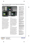
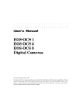
M u l t i - f o r m a t , M u l t i - s t a n d a r d Wa v e f o r m M o n i t o r s
WFM700HD • WFM700A • WFM700M
Features & Benefits
Monitors SD and HD Digital
Component Video – Single
Product for Both Standards
Exclusive Diamond, Split
Diamond and Arrowhead
Displays Offer Unique Insight
Into the Gamut Compliance
of Your Content
Safe Action and Safe Title
Graticules Help Editors and
Operators Easily Identify
Incorrectly Positioned
Video Content
Multi-mode Display
Improves Efficiency by Letting
You View a Wide Variety of
Displays Simultaneously
Closed Caption Detection
and Decode Let Operators
Quickly Verify Correct Closed
Captioning in the Video Content
Ancillary Data Analysis
Reduces the Time and Effort
Needed to Isolate and
Diagnose Problems in the
Data Content of Video Signals
The WFM700 Series of Multi-format Waveform
Monitors offers the monitoring capabilities
needed in the production, post-production,
distribution, and transmission of high-definition
(HD) and standard-definition (SD) digital
video content.
automated measurements, jitter, and data
measurements for both HD and SD formats.
With available digital audio monitoring support,
you can expand the capabilities of any
WFM700 configuration to monitor both digital
video and audio in a single instrument.
For mixed HD/SD environments, the multiformat WFM700A gives you the tools you
need to perform operational monitoring
tasks like checking signal validity and
content quality, setting levels, and verifying
signal paths. The WFM700HD offers an
HD-only version of these same capabilities.
The WFM700M offers all the capabilities
of the WFM700A plus the digital analysis
capabilities important in the design, installation, and maintenance of digital video
systems, including eye diagram with
These products combine the best of traditional
waveform monitors with the measurement
accuracy, repeatability, and stability achievable
with fully digital technology. Their modular
design lets you purchase the capability you
need now and add capabilities later as
your requirements change. Backed by
Tektronix innovation, service, and support,
these modular, multi-format, fully digital
waveform monitors lower your cost of
ownership while offering powerful tools for
monitoring digital video and audio signals.
HD/SD Eye Pattern
Display with Automated
Measurements and Jitter
Display improve Efficiency
in the Installation and
Maintenance of Digital
Video Distribution System
(M module only)
Digital Audio Monitoring
Capability with Surround
Sound Display Verifies
Compliance of Digital Video
and Digital Audio Signals in a
Single Instrument, Conserving
Space, and Lowering Capital
Expenses (requires purchase
of additional module)
TFT Color LCD Display, with
Integrated Touch Screen
Control, Provides a Unique,
Flexible User Interface with
Intuitive, Status-at-a-Glance
Operation
Remote Interface for Access
and Control From Any Location
Applications
Quality Control in the
Production and Post-production
of HD/SD Digital Video Content
Monitoring and Compliance
Checking in the Distribution
and Broadcast of HD/SD
Digital Video
Video Equipment Qualification
and Troubleshooting in the
Installation and Maintenance
of HD/SD Digital Video
Facilities and Systems
1
Waveform Monitors • www.tektronix.com/video_audio
Multi-format, Multi-standard Waveform Monitors
WFM700HD • WFM700A • WFM700M
WFM700 Diamond display.
Tektronix Exclusive
Color Gamut Monitoring
Problems with production and operational
equipment can introduce illegal colors in the
digital video signal, i.e., colors that fall outside
established gamut limits. Every member
of the WFM700 Series has the following
Tektronix patented gamut monitoring displays:
Diamond and Split Diamond – monitoring for
RGB gamut compliance
Arrowhead – monitoring for composite
gamut compliance including luma+chroma
and separate luma limit checking
With these specialized displays you can
significantly reduce the time and effort
needed to perform this critical quality
control task.
Familiar Waveform
Monitoring Displays and
Controls
All WFM700 models offer familiar waveform
displays. You can view digital video signal
components in either an RGB, YRGB, YPb Pr
color space, displayed in parade or overlay
mode. The YRGB color space combines the
Y luminance signal with the RGB component
signals to give you benefits from both traditional color spaces.
In addition to these digital waveform displays,
the WFM700 products can also display a
familiar composite representation of an SDI
digital signal.
2
Waveform Monitors • www.tektronix.com/video_audio
WFM700 Arrowhead display.
WFM700 YRGB Waveform display
in parade mode.
Every WFM700 model offers a rich set of
familiar waveform display controls including:
1-line, 2-line, 1-field, and 2-field sweep
selections
Line and field selects
Flat and low-pass filtering
1x, 5x, 10x and variable gain settings
0% and 7.5% setup levels in the composite
waveform representation
Offset and aligned chroma settings in YPbPr
color space
Horizontal magnification
Selectable graticules including mV, IRE, and
% scales
Tradition and Innovation in
Monitoring Color Amplitude
and Timing
Complementing these full-featured waveform displays, every WFM700 product offers
two specialized displays for monitoring the
color information in digital video signals.
The traditional Vector display for monitoring
PbPr color amplitude
The Tektronix-patented Lightning display for
monitoring luma and chroma amplitudes and
interchannel timing
WFM700 Lightning display.
Automatic Detection of a
Wide Range of Signal
Formats
All WFM700 models have two terminating
inputs for serial digital signals in either
SMPTE 292M format (WFM700 HD,
WFM700A, and WFM700M) or SMPTE
259M format (WFM700A and WFM700M).
The monitor will automatically detect the
signal format and establish the appropriate
settings for the various displays.
All models accept an external reference
signal for synchronization. You can let the
instrument automatically detect the external
reference signal format or manually select
any of the following formats: NTSC, PAL,
1080i (50 Hz, 59.94 Hz, 60 Hz), 1080p
(23.98 Hz, 24 Hz), or 720p (59.94 Hz).
Multi-format, Multi-standard Waveform Monitors
WFM700HD • WFM700A • WFM700M
WFM700 Video Session display.
WFM700 Ancillary Data display.
WFM700 Auxiliary Data Status display.
The following table shows the supported signal formats:
Standard
Physical
Interface
Image
Format
Field/
Frame
Rate
60 Hz
Field/
Frame
Rate
59.94 Hz
Field/
Frame
Rate
50 Hz
Field/
Frame
Rate
30 Hz
Field/
Frame
Rate
29.97 Hz
Field/
Frame
Rate
25 Hz
Field/
Frame
Rate
24 Hz
Field/
Frame
Rate
23.98 Hz
274M
292M
1920x
1080i
X
(D-292)
X
(E-292)
X
(F-292)
274M
292M
1920x
1080p
X
(G-292)
X
(H-292)
X
(I-292)
X
(J-292)
X
(K-292)
274M
292M
1920x
1080sF
X*2
X*2
X*2
X
X
240M/260M
292M
1920x
1035i
X
(A-292)
X
(B-292)
296M
292M
1280x
720p
X
(L-292)
X
(M-292)
X
X
ITU-R
BT.601*1
259M
720x
576i (625)
ITU-R
BT.601*1
259M
720x
483i (525)
X
X
(C-259)
X
(C-259)
*1 ITU-R BT.601 defines sampling for SD serial digital video per SMPTE 259M and ITU-R BT.656.
*2 These segmented-frame format signals are detected as their corresponding interlaced format.
“Status-at-a-Glance”
Video Session Display
Presence or absence of color gamut errors
CRC values
In addition to detecting a wide range of
video signal characteristics, the WFM700
waveform monitors offer valuable status
and error reporting capabilities, like the
unique Video Session display. This display
summarizes a variety of statistics relevant
to video content health and standards
compliance, including:
Signal format and colorimetry
Stuck bits indicator
Presence or absence of ancillary data,
including embedded audio, closed
caption data, or timecodes
Errored seconds, errored fields, and
% errored fields statistics
Presence of closed caption information in
accordance with EIA608 and, if presence,
decode and display the data on picture display
Presence of closed caption information
embedded in accordance with EIA708 and
ARIB B37 standards
Timing Reference and
Auxiliary Data Monitoring
Ancillary Time Code (ATC) and Vertical
Interval Time Code (VITC) values
Every WFM700 Series product can detect
information contained in the horizontal and
vertical synchronization intervals in the
digital video, including:
Presence of V-chip data and, if presence,
the decoded rating information
Start-of-Active-Video (SAV) and
End-of-Active-Video (EAV)
Error detection and reporting per
SMPTE RP165 for standard definition
and SMPTE 292M for high definition
Presence of ARIB STD-B39, ARIB STD-B35,
ARIB TR-B22, and ARIB TR-B23
Depending on your preference, WFM700
waveform monitors can either show the SAV
and EAV in waveform display or strip out
this data prior to display.
Waveform Monitors • www.tektronix.com/video_audio
3
Multi-format, Multi-standard Waveform Monitors
WFM700HD • WFM700A • WFM700M
WFM700 picture display with decoded
EIA608 Closed Caption data.
The Ancillary Data Display helps you view
information contained in any ancillary data
packet by specifying the appropriate first
data identifier (DID) and secondary data
identifier (SDID). All WFM700 Series waveform monitors can display the data as a
table of data words in hex format. The display
can also show information on data block
and count, packet type, and checksums.
User-adjustable Alarms
and Event Logging
Further enhancing the capability available
with the Video Session display, all WFM700
Series instruments can report and log a
wide range of alarm conditions, including:
Input signal or external reference signal
missing or format mismatch
Color gamut errors
EAV/SAV missing or mismatch with
line number
SAV placement error
CRC and EDH errors, code word violations,
or field and line length errors
Ancillary data and closed caption
present/absent errors, parity errors,
or checksum errors
4
Waveform Monitors • www.tektronix.com/video_audio
WFM700 Event Log.
Every WFM700 model maintains an event
log with each entry stamped with the timeof-day the event occurred. You can also
configure event logging to time stamp
events with a VITC value.
Convenient User Interface
Features and Display Modes
WFM700 waveform monitors offer many
convenient user interface features and
display modes, including:
An integrated thin-film LCD color display
with touch screen
Full-screen and thumbnail picture display
Multi-mode display capability that lets you
flexibly combine two displays into a single,
split-screen view
Freeze mode for comparing live signals
against a stored reference
Electronic graticules and digital cursors
Safe action and safe title graticules that help
you easily identify incorrectly positioned
video content
Up to 42 stored presets
Print screen capability, context sensitive on-line
help, and complete instrument diagnostics
Video monitors and television sets may
overscan, i.e., placing parts of the image
outside the display area. Incorrect placement
of graphics, logos, and other branding elements can obscure text or essential action.
The Safe Action and Safe Title graticules
help you quickly assure that the action and
WFM700 Multi-mode display.
titles you produced lie within the safe areas
defined in SMPTE RP218. The Safe Action
Area is the maximum image area within
which all significant action shall be contained
while the Safe Title Area is the maximum
image area within which all significant titles
should be contained.
Powerful Digital Video
Waveform Measurement
Available
For in-depth technical measurement of
digital video signals, you need additional
capabilities. For making highly precise
inter-channel amplitude and timing measurements, every WFM700 model offers the
familiar Bowtie display. The WFM700M
offers more comprehensive measurement
capability, adding the following displays
to those offered on the WFM700A
and WFM700HD:
Data display
Eye pattern display
Jitter display
The automated Eye measurements include
amplitude, rise time, fall time, rise overshoot,
fall overshoot and a histogram of the Eye
sample amplitude values. In Jitter Display
mode, the WFM700M demodulates the signal jitter, displays a trace of video-correlated
jitter vs. time, and measures peak-to-peak
time jitter in the active display.
Multi-format, Multi-standard Waveform Monitors
WFM700HD • WFM700A • WFM700M
WFM700 Data display.
Digital Audio Monitoring
Available on All Models
All members of the WFM700 Series detect
and report the presence or absence of
embedded audio channels. You can add
more extensive capability for monitoring
AES/EBU digital audio channels by including Option DG in your order for any
WFM700 Series waveform monitor. You
can add this audio monitoring capability to
a previously purchased WFM700 model by
ordering the WFM7DG field upgrade.
WFM700 Series digital audio monitoring
and measurement features include:
Monitoring of up to 16 embedded digital
audio channels
4 AES/EBU audio inputs/outputs for monitoring
up to 8 non-embedded audio channels, or
producing up to 8 channels of de-embedded
audio output
Support for multi-channel digital audio in 5.1
and 7.1 formats
Audio Level Bar display of 2, 4, 6, or 8 audio
channels with true peak, PPM, and Extended
VU meter ballistics and selectable scaling
Single-axis Phase Correlation Meter showing
the phase relationship between signals on an
audio channel pair
Flexible Lissajous display showing the phase
relationship between channels, with X/Y or
Sound Stage (L/R) axis orientation and
automatic gain control
WFM700 Eye Pattern display.
Surround Sound Display for 5.1 multi-channel
digital audio format with total volume, center
volume, phantom source and dominant
sound indicator as well as LS and RS
correlation meter
Surround Sound Display helps you more
precisely mix, master, edit and verify 5.1
multi-channel digital audio. The visual
representation of the sound image
complements your auditory experience.
WFM700 5.1 multi-channel Surround Sound
display.
Phantom source indicators (PSIs) located on
each side of the display show the location
of potential phantom sound sources formed
by adjacent channels.
The display also has a cross-hair pointer that
shows the location of the dominant sound in
the sound image, and a correlation meter at
the bottom of the display that shows the
correlation between the Ls and Rs channel.
The display shows the audio level balance
among the left (L), right (R), left-surround
(LS), and right-surround (RS) channels on the
ruled scales radiating from the center. A
vertical bar between the L and R channels
shows the center (C) channel audio level.
The polygon formed by connecting the level
indicator endpoints shows the total sound
volume formed by the L, R, LS, and RS
channels. This connecting line will bend
away from the center if the two signals
have a positive correlation, will bend
towards the center if the signals have a
negative correlation, and will not bend if
the signals have no correlation. In addition
to this total volume indicator, the display
has a separate center volume indicator by
connecting the ends of the L, C, and R
channel level by straight lines.
Waveform Monitors • www.tektronix.com/video_audio
5
Multi-format, Multi-standard Waveform Monitors
WFM700HD • WFM700A • WFM700M
The audio monitoring module supports the embedded and AES/EBU formats shown in the
following table:
Audio Standard
Physical Interface
48.0 kHz
44.1 kHz
AES3-1992 (r1997)
AES-3id-2001
X
X
AES3-1992 (r1997)
SMPTE 259M
X
AES3-1992 (r1997)
SMPTE 292M
X
Complementing these standard displays, the
Channel Status display decodes the information in the Channel Status block defined
in AES3-1992 (r1997) for both consumergrade and professional-grade audio.
Audio monitoring support adds several
alarm conditions to the list of video alarms
described earlier, including detection of:
Audio CRC errors
Clip, mute, over, and silence conditions
Audio parity errors
Embedded audio absence and AES audio
unlock
Like the session display used to monitor
video signals, all WFM700 models with
audio monitoring capability offer an Audio
Session screen that lets you quickly check
the health of any digital audio channels and
track key audio signal parameters. Key
fields include:
Highest true peak, highest uninterpolated
peak, and highest bar reading
Sample rate and active bits
The number of clips, mutes, overs,
and silences
Invalid samples
Detected receiver errors
Sampling Frequency
Multiple Inputs/Outputs for
Easy System Integration
In addition to the inputs and outputs
described earlier, every WFM700 model
has the following connections:
WFM700 Back Panel with two WFM700M
video input modules and an audio input
module installed.
Characteristics
Serial Digital Video Interface
Video Inputs – 2 per card – only one active at
a time.
Input Type – 75 Ω BNC, internally terminated.
VGA output for viewing the LCD display
on a detached VGA monitor
Launch Amplitude Accommodation –
800 mV ±10% for full specification.
800 mV ±30% up to 20 dB cable attenuation.
Analog component video picture
monitor outputs
Jitter Tolerance – 0.4 UIp-p typical above 2 MHz.
Return Loss – 15 dB to 1.5 GHz.
VGA picture monitor output that follows
the component picture monitor output
for viewing the picture on an inexpensive
VGA display
Looping inputs for bi-level and tri-level sync
One switched SDI output that follows
the selected input
An SD SDI picture monitor output
Network Access and Control
The WFM700 Series offers two forms of
remote access and control:
A 9-pin remote control port reports alarm
conditions and lets you control the monitor
by selecting one of seven available
instrument presets
A network remote control interface lets you
view the WFM700 displays using a standard
Web-browser over an Ethernet-based network
SNMP (Simple Network Management
Protocol) speeds development and integration
of remote control software for external
control and reporting of major functions of
the WFM700, including all error alarms
Isolation Between Inputs – >45 dB to 1 GHz.
Switched Serial Video Output
Format – 1.485 Gbps or 270 Mbps repeat of
selected input.
Output Level – 800 mVp-p ±5% into 75 Ω load.
Return Loss – 15 dB to 1.5 GHz.
Output Type – 75 Ω BNC.
External Reference
Sync Format – NTSC, PAL, 1080i 50 Hz,
1080i 59.94 Hz, 1080i 60 Hz, 720p 59.94 Hz,
1080p 23.98 Hz, 1080p 24 Hz.
Input Type – 75 Ω BNC passive loop.
Return Loss – 40 dB to 30 MHz.
Hum – Operates with 500 mVp-p.
Signal/Noise – Operates to 25 dB.
Serial SD Only Monitor Output
Content Follows Active Input With Brightups –
SD only digital version of RGB/Y'P'bP'r analog pix
monitor output on Ref board.
Rate – 270 Mbps.
Signal Level – 800 mV ±5% into 75 Ω.
Return Loss – 20 dB, 5 MHz to 270 MHz.
Output Type – 75 Ω BNC.
Picture Monitor Outputs
Signal Format, BNC Outputs – Y, P'b, P'r with
sync on Y, RGB with sync on all, HD and SD.
HD sync is tri-level.
Signal Format, VGA D-sub Outputs – Same signal
as on BNC outputs, also have TTL H and V drive.
6
Waveform Monitors • www.tektronix.com/video_audio
Multi-format, Multi-standard Waveform Monitors
WFM700HD • WFM700A • WFM700M
Impedance – 75 Ω unbalanced.
Active Video Accuracy – 700 mV ±5%p-p
(Y'P'bP'r mode).
Black (Blanking) Output Level – 0 mV ±25 mV
for HD and SD.
Eye Pattern Display
Type – Equivalent time sampler.
Signal Bandwidth – 50 kHz to 2.5 GHz at
–3 dB point.
Frequency Response, SD – Y, G, B and R ±5%
to 5.5 MHz.
Timebase Jitter – (Note: in 1 kHz high pass filter)
(HD) – 70 ps, typical.
(SD) – 150 ps, typical.
Frequency Response, HD – Y, G, B and R ±8%
to 30 MHz.
Eye Clock Bandwidth Accuracy – Actual –3 dB
point within 10% of nominal.
AES Audio Interface
Audio Inputs – 4 inputs, 8 audio channels, meets
Requirements of AES-3id-2001.
Input Type – 75 Ω BNC, internally terminated,
unbalanced.
Input Amplitude Range – 0.2 V to 2 Vp-p.
Input Sample Rate – 32 k to 96 k samples/sec.
Input Lock Range – >±5%, typical.
Input Return Loss – Better than 25 dB from 0.1 to
6 MHz.
Audio Outputs – Up to 8 audio channels from
Embedded Audio only.
Output Format – 48 kHz, 20 bit, meets requirements of SMPTE 276M-1995 (AES-3id-2001).
Output Amplitude Range – 0.9 V to 1.1 Vp-p
into 75 Ω.
Output Sample Rate – Locked to embedded
sample rate (nominally 48 kHz).
Output Jitter – Meets AES3-1997.
Output Return Loss – Better than 25 dB
0.1 to 6 MHz.
Waveform Vertical Deflection
Vertical Measurement Accuracy Using Graticule
or Cursor –
At 1x, ±0.5% of 700 mV full scale.
At 5x, ±0.2% of 700 mV full scale.
At 10x, ±0.1% of 700 mV full scale.
Gain – 1x, 5x, 10x, variable.
Variable Gain Range – 0.25x to 14x.
Frequency Response, HD*1 –
Luminance channel (Y): 50 kHz to 30 MHz ±0.5%.
Chrominance channels (P'b, P'r): 50 kHz to 15 MHz
±0.5%.
*1 For monochrome signals, R, G and B bandwidths
equal Y bandwidth.
Waveform Horizontal Deflection
Sweep Accuracy – ±0.5%, all rates, fully
digital system.
Sweep Linearity – 0.2% of time displayed
on screen, fully digital system.
Rates – 1, 2, 3, 4 line or field, depending
on mode.
Line Select – Selected line in 1 line, selected first
line in 2 line or parade.
Display Modes, SD –
Overlay: Overlays all bits to form each eye opening.
Useful for observing peak jitter.
10 Eye: Displays eye relative to the parallel clock
and line sync. Useful for observing jitter correlated to
line rate and word clock.
Display Modes, HD –
Overlay: Overlays all bits to form each eye opening.
Useful for observing peak jitter.
20 Eye: Displays eye relative to the parallel clock
and line sync. Useful for observing jitter correlated
to line rate and word clock.
Jitter Display
Type – Demodulated recovered clock per
SMPTE RP184.
Digital Readout – Accuracy: <0.05 UI + 10%,
typical, of reading for jitter frequencies from three
times high-pass filter selection to 1 MHz.
Note: High-pass filter selection is set in Jitter
Waveform Mode.
Jitter Waveform Gain Error – <0.1 UI + 10%,
typical, of reading for jitter frequencies from three
times high-pass filter selection to 1 MHz.
Jitter Waveform High-pass Filter Selection –
10 Hz, 1 kHz, 10 kHz, 100 kHz.
Jitter Output – 100 mV/UI, ±10% into 75Ω load.
Jitter Frequency Response – –3 dB at 5 MHz
(typical).
0.25 dB steps at 0 to –70 dB scale, for signals
above –40 dB FS.
Level Meter Accuracy –
0.2 dB from 20 Hz to 20 kHz with 0 to –40 dB FS
sine-wave input. PPM Ballistic mode except within
7 Hz of some submultiples of the 192 kHz
oversampling frequency. For example:
13.714 kHz ±7 Hz – 0.22 dB.
16.0 kHz ±7 Hz – 0.30 dB.
19.2 kHz ±7 Hz – 0.43 dB (worst case).
General Specifications
Power
Mains Voltage Range – 100 to 240 VAC ±10%.
Mains Frequency – 50 or 60 Hz.
Power Consumption (typical) –
≤100 W with 1 Video Input Module.
≤125 W with 2 Video Input Modules.
150 W max.
VGA O/P – This connector allows the front panel
display to be replicated on a remote VGA monitor.
Ethernet Connector – Allows the instrument to be
connected to a 10/100Base-T Ethernet circuit for
remote control and firmware update.
Environmental
Temperature –
0 ºC to +40 ºC (operating).
–20 ºC to +60 ºC (nonoperating).
Humidity – 20% to 80% RH at up to 40 ºC,
noncondensing (operating).
Altitude –
to 3,000 m (operating).
to 12,192 m (nonoperating).
Safety
Designed and tested for compliance with:
ANSI/ISA s82.02.01, Can/CSA C22.2 No. 1010.1,
IEC 61010-1, UL 3111-1, 93/68/EEC and
EN 61010-1.
RGB Gamut Error Detection
Detection Level –
High Limit, +630 mV to +756 mV in 1 mV steps.
Low Limit, –50 mV to +35 mV in 1 mV steps.
Arrowhead (NTSC/PAL
Composite Gamut Limit
Display Mode)
Detection Level –
Accuracy, ±7 mV.
Luma+Chroma High Limit (NTSC-derived formats),
90 IRE to 135 IRE in 1 IRE steps.
Luma+Chroma Low Limit (NTSC-derived formats),
–50 IRE to –10 IRE in 1 IRE steps.
Luma+Chroma High Limit (PAL-derived formats),
630 mV to 950 mV in 1 mV steps.
Luma+Chroma Low Limit (PAL-derived formats),
–400 mV to –100 mV in 1 mV steps.
Luma only High Limit, 90% to 108% in 1% steps.
Luma only Low Limit, –6% to +5% in 1% steps.
Audio Level Meter
EMI
Tested for compliance with:
FCC, CFR Title 47, part 15, Subpart B,
Class A
EN 55103-1/2, Class B emissions
European EMC directive, video standard
Physical
Characteristics
Dimensions
mm
in.
Height
133.4
5.25
Width
215.9
8.5
Depth
460.4
18.125
Weights
kg
lb.
Net
5.5
12.125
Shipping (approx.)
9.6
21.164
Level Meter Resolution – 0.05 dB steps at 10 dB
scale, from full scale to –40 dB FS.
Waveform Monitors • www.tektronix.com/video_audio
7
Multi-format, Multi-standard
Waveform Monitors
Contact Tektronix:
ASEAN / Australasia / Pakistan (65) 6356 3900
WFM700HD • WFM700A • WFM700M
Austria +43 2236 8092 262
Belgium +32 (2) 715 89 70
Brazil & South America 55 (11) 3741-8360
Ordering Information
The following models complete with one video
input module (two video inputs).
Instruments
WFM700HD
SMPTE 292M Serial Digital Waveform Monitor.
WFM700A
ITU-R BT.601 and SMPTE 292M Serial Digital
Waveform Monitor.
WFM700M
ITU-R BT.601 and SMPTE 292M Serial Digital
Waveform Monitor with additional video
measurements.
Optional Modules
Options installed and tested at time of manufacture.
Maximum of two video modules and one audio
module in an instrument.
Option 2HD – Serial digital monitoring module for
SMPTE 292M.
Option 2A – Serial digital monitoring module for
ITU-R BT.601 and SMPTE 292M.
Option 2M – Serial digital measurement module
for ITU-R BT.601 and SMPTE 292M.
Option DG – AES/EBU digital audio monitoring
module.
Service
Canada 1 (800) 661-5625
Opt. C3 – Calibration Service 3 Years.
Opt. D1 – Calibration Data Report.
Opt. D3 – Calibration Data Report 3 Years
(with Option C3).
Opt. R3 – Repair Service 3 Years.
Central Europe & Greece +43 2236 8092 301
Denmark +45 44 850 700
Finland +358 (9) 4783 400
France & North Africa +33 (0) 1 69 86 80 34
Germany +49 (221) 94 77 400
Language
Hong Kong (852) 2585-6688
Opt. L0 – English user manual.
Opt. L5 – Japanese user manual.
Opt. L9 – Korean user manual.
India (91) 80-22275577
Italy +39 (02) 25086 1
Japan 81 (3) 6714-3010
Field Upgrade Kits
Mexico, Central America & Caribbean 52 (55) 56666-333
Shipped as a kit and installed in the field.
Maximum of two video modules and one audio
module in an instrument.
WFM7HD – Serial digital monitoring module for
SMPTE 292M.
WFM7A – Serial digital monitoring module for
ITU-R BT.601 and SMPTE 292M.
WFM7M – Serial digital measurement module
for ITU-R BT.601 and SMPTE 292M.
WFM7DG – AES/EBU digital audio monitoring
module.
Opt. IF – Upgrade Installation Service.
The Netherlands +31 (0) 23 569 5555
Norway +47 22 07 07 00
People’s Republic of China 86 (10) 6235 1230
Poland +48 (0) 22 521 53 40
Republic of Korea 82 (2) 528-5299
Russia, CIS & The Baltics +358 (9) 4783 400
South Africa +27 11 254 8360
Spain +34 (91) 372 6055
Sweden +46 8 477 6503/4
Taiwan 886 (2) 2722-9622
Optional Accessories
Power Plug Options
Opt. A0 – North America power.
Opt. A1 – Universal EURO power.
Opt. A2 – United Kingdom power.
Opt. A3 – Australia power.
Opt. A5 – Switzerland power.
Opt. A6 – Japan power.
Opt. AC – China power.
Accessories
United Kingdom & Eire +44 (0) 1344 392400
WFM7F02 – Portable cabinet includes handle,
feet, tilt bail and front panel cover.
WFM7F03 – Plain cabinet.
WFM7F05 Opt. ON or Opt. NN – Dual rackmount
for 1700 Series, WFM601 Series, WFM700 Series,
760A and 764.
071-0915-xx– Service Manual for WFM700
Series products (WFM700HD, WFM700A
and WFM700M).
USA 1 (800) 426-2200
USA (Export Sales) 1 (503) 627-1916
For other areas contact Tektronix, Inc. at: 1 (503) 627-7111
Last Update March 01, 2004
Our most up-to-date product information is available at:
www.tektronix.com
Opt. 01 – Portable cabinet.
Opt. 02 – Dual rackmount.
Product(s) are manufactured
in ISO registered facilities.
Copyright © 2003, Tektronix, Inc. All rights reserved. Tektronix products are covered
by U.S. and foreign patents, issued and pending. Information in this publication
supersedes that in all previously published material. Specification and price change
privileges reserved. TEKTRONIX and TEK are registered trademarks of Tektronix,
Inc. All other trade names referenced are the service marks, trademarks or registered trademarks of their respective companies.
07/04
8
Waveform Monitors • www.tektronix.com/video_audio
HB/WOW
25W-14575-8
With compliments
Helmut Singer Elektronik
www.helmut-singer.de [email protected]
fon +49 241 155 315
fax +49 241 152 066
Feldchen 16-24 D-52070 Aachen Germany
Specifications
The following tables list the specifications for the Tektronix WFM700 Standard
Definition/High Definition Multiformat Video Waveform Monitor. Items listed
in the Performance Requirement column are generally quantitative, and can be
tested by the Performance Verification procedure in the WFM700 Series Service
Manual. Items listed in the Reference Information column are useful operating
parameters that have typical values; information in this column is not guaranteed.
The specifications listed in the Electrical Specifications portion of these tables
apply over an ambient temperature range of +0 _C to +40 _C. The rated
accuracies are valid when the instrument is calibrated in an ambient temperature
range of +20 _C to +30 _C.
Electrical Specifications
Table 1- 4: Waveform vertical deflection
Characteristic
Performance requirement
Vertical Measurement Accuracy, YPbPr
1X
0.5% of 700 mV full scale mode
5X
0.2% of 700 mV full scale mode
10X
0.1% of 700 mV full scale mode
Gain
Reference information
Limited byy the screen resolution and
internal processing. Fully digital system.
X1, X5, and X10
Variable Gain Range, Typical
0.25X to 14X
Frequency Response - HD
Luminance Channel (Y)
50 kHz to 30 MHz, 0.5%
Chrominance Channels (Pb, Pr)
50 kHz to 15 MHz, 0.5%
Frequency Response - SD
Luminance Channel (Y)
50 kHz to 5.75 MHz, 0.5%
Chrominance Channels (Pb, Pr)
50 kHz to 2.75 MHz, 0.5%
YPbPr to RGB Conversion Accuracy
0.35%, nominal
With compliments
Helmut Singer Elektronik
www.helmut-singer.de [email protected]
fon +49 241 155 315
fax +49 241 152 066
Feldchen 16-24 D-52070 Aachen Germany
WFM700 Series Waveform Monitors Technical Reference
1- 19
Specifications
Table 1- 4: Waveform vertical deflection (Cont.)
Characteristic
Performance requirement
Step Response, Typical
Reference information
Sine-squared bars
Preshoot
SD
≤ 0.3% peak (2T5 bar)
HD
≤ 0.5% peak (2T30 bar)
Overshoot
SD
≤ 0.3% peak (2T5 bar)
HD
≤ 0.5% peak (2T30 bar)
Ringing
SD
≤ 0.4% peak-peak (2T5 bar)
HD
≤ 0.8% peak-peak (2T30 bar)
Most of the error seen on the display
comes from the inherent ringing in the
digital data. The response of the WFM700
is close to the theoretical limit of a perfect
sinx/x reconstruction filter.
Pulse Response, Typical
Blackman pulse
Baseline Ringing
SD
≤0.6% peak-peak (2T5)
HD
≤0.7% peak-peak (2T30)
Pulse-to-bar ratio 0.995:1 to 1.005:1 on appropriate Sine Squared or Blackman 2T
pulse.
A sine-squared pulse near Nyquist is not
band-limited and so inherently has ringing
much larger than the WFM700 filter. A three
term Blackman pulse with the same HAD has
much less inherent ringing, so it is a better
choice for most testing. See Digital to Analog
Conversion, Data and Filter Requirements,
SMPTE Journal Mar 1995, Vol. 104, Fibush,
Baker, Penny.
With compliments
Helmut Singer Elektronik
www.helmut-singer.de [email protected]
fon +49 241 155 315
fax +49 241 152 066
Feldchen 16-24 D-52070 Aachen Germany
1- 20
WFM700 Series Waveform Monitors Technical Reference
Specifications
Table 1- 4: Waveform vertical deflection (Cont.)
Characteristic
Performance requirement
Reference information
Interpolation Filter Group Delay, Typical
HD
1 ns
SD
1 ns
Tilt, Typical
Field Rate
0.1%
Line Rate
0.1%
Off Screen Recovery, Typical
0.1% variation in baseline of a 5 MHz
modulated pulse when positioned anywhere on screen
Offset, Typical
Pr and Pb can be displayed aligned to Y or
offset by 350 mV.
Table 1- 5: Waveform horizontal deflection
Characteristic
Performance requirement
Reference information
Accuracy
0.5%, all rates
Fully digital system
Linearity
0.2% of time displayed on screen
Fully digital system
Sweep
Timing Cursor Registration and Readout
Accuracy, Typical
0.5% of sweep time displayed on
screen
Rates
1, 2, 3, or 4 line or field depending on
mode.
Line Select
Selected Line in 1 Line
Selected first line in 2 Line or Parade
With compliments
Helmut Singer Elektronik
www.helmut-singer.de [email protected]
fon +49 241 155 315
fax +49 241 152 066
Feldchen 16-24 D-52070 Aachen Germany
WFM700 Series Waveform Monitors Technical Reference
1- 21
Specifications
Table 1- 6: Eye pattern display
Characteristic
Performance requirement
Type
Reference information
Equivalent Time Sampler
Signal Bandwidth
50 KHz to 2.5 GHz at - 3 dB point
Time Base Jitter
SD
150 ps p-p in 1 kHz high-pass filter mode
HD
70 ps p-p in 1 kHz high-pass filter mode
Eye Clock Recovery Bandwidth Settings
Eye Clock Recovery Bandwidth Accuracy
Clock recovery bandwidth can be set to
10 Hz, 100 Hz, or 1000 Hz high pass filter
Actual - 3 dB frequency within 10% of
nominal
Jitter Attenuation Error
10 Hz or 100 Hz Bandwidth
<10% for frequencies greater than 2 times
the Clock BW setting
1 kHz Bandwidth
<-- 10%, +20% for frequencies from 2 KHz
to 10 kHz; <10% for frequencies above
10 kHz
Display Modes
SD
Overlay
Overlays all bits to form each eye opening.
Useful for observing peak jitter.
10 Eye
Displays eye relative to the parallel clock
and line sync. Useful for observing jitter
correlated to line rate and word clock.
Overlay
Overlays all bits to form each eye opening.
Useful for observing peak jitter.
20 Eye
Displays eye relative to the parallel clock
and line sync. Useful for observing jitter
correlated to line rate and word clock.
HD
Deflection Factor
Vertical
800 mV 5% with an 800 mVp-p input
signal
1%, fully digital system
Horizontal
With compliments
Helmut Singer Elektronik
www.helmut-singer.de [email protected]
fon +49 241 155 315
fax +49 241 152 066
Feldchen 16-24 D-52070 Aachen Germany
1- 22
WFM700 Series Waveform Monitors Technical Reference
Specifications
Table 1- 7: Jitter display
Characteristic
Performance requirement
Reference information
Type
Demodulated recovered clock, per
SMPTE RP184 specifications.
High-Pass Filter Settings
Can be set to 10 Hz, 1 kHz, 10 kHz, or
100 kHz.
Applies to digital readout, jitter waveform,
and jitter output.
High-Pass Filter Attenuation
- 2 dB to - 4 dB at specified frequency.
High-End Frequency Response, Typical
Applies to digital readout, jitter waveform,
and jitter output.
- 3 dB at > 5 MHz.
Applies to digital readout, jitter waveform,
and jitter output.
Dynamic Range,
Range Typical
Maximum is a function of jitter frequency and standard:
Applies
pp to digital
g readout,
readout, jjitter waveform,
waveform,
andd jijitter output.
10 Hz to 50 kHz, HD
9 UIp-p
10 Hz to 50 kHz, SD
7 UIp-p
100 kHz to 5 MHz
Decreasing linearly to 0.2 UIp-p at 5 MHz
Minimum (noise floor) is a function of
high-pass filter selection:
10 Hz, HD
60 ps typical
1 kHz, 10 kHz, HD
60 ps typical
100 kHz, HD
30 ps typical
All HPF settings, SD
200 ps typical
Digital Readout Type
Indicates timing jitter or alignment jitter,
depending on high-pass filter selection.
Digital Readout
Error, Typical
< 0.05 UI, +10% of reading for jitter
frequences from 3 times high-pass filter
selection to 1 MHz.
Resolution
0.01 UI
Jitter Waveform
Gain Error, Typical
< 0.1 UI +10% for jitter frequencies from 3
times high-pass filter selection to 1 MHz
Scale
Horizontal Modes
1 Line, 2 Line, 1 Field, 2 Field
Vertical Modes
1 UI / div, 0.2 UI / div, 0.1 UI / div
Jitter Output
WFM700 Series Waveform Monitors Technical Reference
100 mV / UI, 10%, into 75 Ω load.
In Jitter Mode only
1- 23
Specifications
Table 1- 8: Component Vector mode
Characteristic
Performance requirement
Reference information
Vertical Bandwidth, Typical
SD
1.2 MHz
HD
4.5 MHz
Vertical Gain Accuracy
0.5%
Horizontal Gain Accuracy
0.5%
Display to Graticule Registration
0.5%
Fully digital system
Fully digital system limited by sample
resolution
Vector Display
PB is displayed on horizontal axis and PR is
displayed on vertical axis
Table 1- 9: Lightning and Diamond modes
Characteristic
Performance requirement
Reference information
Vertical Gain Accuracy
0.5%
Fully digital system
Electronic Graticule Display
Diamond
RGB deflection axis indicated
Split Diamond
Offsets the top and bottom diamonds
horizontally for better viewing of black
gamut space.
Lightning
Displays signal components as follows:
Y vertically
Pb horizontally on top half of display
Pr horizontally on bottom half of display
Table 1- 10: Data display mode
Characteristic
Performance requirement
Reference information
Digital Waveform
Non-interpolated waveform display. Cursor
identifies selected sample value (hex,
decimal, binary). Cross-hair cursor inserted
on picture monitor output shows selected
line and sample.
Digital List
Sequential list of sample values in table
format. Cursor identifies selected sample.
Display Format
HEX, DEC, BIN
1- 24
WFM700 Series Waveform Monitors Technical Reference
Specifications
Table 1- 11: Arrowhead mode (NTSC/PAL composite limit display)
Characteristic
Performance requirement
Reference information
Signal to Graticule Accuracy
1%, 100 IRE (700 mV), and 131 IRE
(PAL values in parenthesis)
Composite Limit Cursor Accuracy
0.5% at 100 IRE, 110 IRE, 120 IRE, and (PAL values in parenthesis)
131 IRE (700 and 950 mV)
Composite Limit Detection Level Accuracy
Detection level 7 mV
90% to 135% in 1% steps
Table 1- 12: Bowtie mode
Characteristic
Performance requirement
Reference information
SD
≥34 dB at 2.5 MHz
With SD 2.5 MHz, 350 mV Bowtie test
signal. Null amplitude measured with
cursors at 10x gain.
HD
≥40 dB at 5 MHz
With HD 5 MHz, 700 mV Bowtie test
signal. Null amplitude measured with
cursors at 10x gain.
SD
0.5 ns
With SD 2.5 MHz, 20 ns markers Bowtie
test signal. In H MAG, null within 0.5
division of center marker.
HD
0.1 ns
With HD 5 MHz, 1 ns markers Bowtie test
signal. In H MAG, null within 0.5 division of
center marker.
Performance requirement
Reference information
Common Mode Rejection Ratio
Interchannel Timing Match
Table 1- 13: Freeze/Capture function
Characteristic
Delay Time from Button Push
< 3 frames at input frame rate
Saved Capture Size
1 frame at VGA display rate
Number of Captures
1
WFM700 Series Waveform Monitors Technical Reference
1- 25
Specifications
Table 1- 14: Data error detection (EDH / Status)
Characteristic
Performance requirement
Reporting Means
Reference information
Data errors shown in Video Status/Session
and Alarm Status displays. On-screen
notification, audible beep, logging, and
ground-closure remote output can also be
enabled through the Configure menu.
Data Integrity
SD
Both active picture and full field checks.
Field rate resolution.
Complies with SMPTE RP165.
HD
Both Y and Color Difference checks.
Field rate Resolution.
Indicates CRC check-word errors for
signals including EDH (Error Detection and
Handling).
Error Statistics
Indicates errored fields, % errored fields,
and asynchronous errored seconds. Active
picture and full field statistics are compiled
separately.
Ancillary Data
Indicates the presence of ancillary data
(other than audio and EDH) and indicates
parity or checksum errors.
Bit Activity
Indicates if any of the 10 data bits are stuck
high or low during the active picture of an
entire field.
Signal Format
Indicates bit rate and detected format.
Format Errors
Indicates serial signal format errors.
Detected Errors:
SAV placed incorrectly relative to EAV
Line length error
Field length error
SDI code word violation
292M line mismatch (HD only)
Input Signal Unlocked
Indicates input unlocked due to degraded,
missing or inappropriate input signal.
Table 1- 15: RGB GAMUT error detection
Characteristic
Performance requirement
Reference information
Detection Level
High Limit
+630 mV to +756 mV in 1 mV steps
Low Limit
- 50 mV to +35 mV in 1 mV steps
Detection Level Accuracy
1- 26
3.5 mV
WFM700 Series Waveform Monitors Technical Reference
Specifications
Table 1- 16: Closed caption detection
Characteristic
Performance requirement
Reference information
Detected Formats
Any selected video input; detects presence
of EIA 608, EIA 708, and ARIB STD-B37
Closed Captioning
Decoded Formats
EIA 608 (VBI)
EIA 608 (ANC)
EIA 608 (708)
EIA/Line 21 (VBI) Line Detection Range
Auto Detect
Lines 11 to 25
Manual Detect
Lines 5 to 25
Table 1- 17: Timecode decoding
Characteristic
Performance requirement
Sources
Reference information
Any selected video input
SD
Extracts and decodes VITC (SMPTE 12M)
HD
Extracts and decodes VITC (SMPTE 12M)
and ancillary timecode (SMPTE RP188)
Table 1- 18: Audio mode (without Option DG)
Characteristic
Performance requirement
Embedded Audio
Reference information
Identifies the presence of up to 16 channels
of AES/EBU digital audio. Presence is
detected by looking at AES protocol.
Table 1- 19: Audio alarms (Option DG only)
Characteristic
Performance requirement
Reference information
Audio Level Alarms
Warns of mute, clip, silence or over
condition on an audio channel
Audio Error
Warns of CRC and parity errors and of
validity bit set
Audio Unlocked
Warns of unlocked condition on an AES
input
Group Sample Phase
Warns of sample phase errors between the
two selected embedded audio groups
WFM700 Series Waveform Monitors Technical Reference
1- 27
Specifications
Table 1- 20: Audio level meter displays (Option DG only)
Characteristic
Performance requirement
Bar Modes
Reference information
The user can configure the response
dynamics (ballistics), reference levels, peak
hold, and scale of the meters to suit the
monitoring needs of the particular installation or situation. Each pair has a phase
correlation meter.
Stereo Pairs
All 4 channel pairs with phase correlation
meters
Surround
8 channels (L, C, R, Ls, Rs, LFE, Lo, Ro)
with phase correlation meters for L & R,
Ls & Rs, and Lo & Ro.
Audio Sources
Monitoring the signal levels and stereo
phase of AES/EBU digital audio or digital
audio embedded in serial digital video
Level Meter Resolution
0.05 dB steps at 10 dB scale, for from full
scale to - 40dB FS
0.25 dB steps at 0 to - 70 dB scale, for
signals above - 40 dB FS
Metering Ballistics
Selectable from true peak, PPM, and
Extended VU
Peak Program Meter
Per IEC 268-- 10A and IEEE std. 152-- 1991
True Peak
PPM decay characteristics, no attack delay
Extended VU
VU meter as defined in IEEE 152-- 1991,
but with an extended dB-linear scale
Peak Hold
True peak indicator remains at the most
recent peak for user selectable time of 1 to
10 seconds
Clip Indication Delay Count
Consecutive FS samples for Clip Indication, user selectable Off or 1 to 100
Only the 16 most significant bits are
checked for 0x7FFF or 0x8000 to identify a
full-scale sample
Mute Indication Delay Count
Consecutive “0” samples for Mute Indication, user selectable Off or 1 to 100
Clip/Mute Hold Time
1 to 30 seconds, user selectable
With compliments
Helmut Singer Elektronik
www.helmut-singer.de [email protected]
fon +49 241 155 315
fax +49 241 152 066
Feldchen 16-24 D-52070 Aachen Germany
1- 28
WFM700 Series Waveform Monitors Technical Reference
Specifications
Table 1- 20: Audio level meter displays (Option DG only) (Cont.)
Characteristic
Performance requirement
Silence Indication Threshold
Reference information
Audio level below which the signal will be
considered “silent.” User selectable from
0 dB FS to - 90 dB FS.
Used to trigger on-screen indication and
alarms
Over Level Indication Threshold
Audio level above which the signal will be
considered “over level.” User selectable
from 0 dB FS to - 90 dB FS.
Used to trigger on-screen indication and
alarms
Silence / Over Indication Delay
Off or 1 to 30 seconds, user selectable
Indication and alarm will not be asserted
until signal stays below silence threshold or
above over threshold for this number of
consecutive seconds
Adjustable Peak Program Level
Range 0 to - 30 dBFS
Adjustable Test Level
Range 0 to - 60 dBFS
Set 0 dB Mark
Selections are Digital Full-Scale (dBFS),
Peak Program (dB), or Test Level (dB)
Table 1- 21: Audio lissajous display (Option DG only)
Characteristic
Performance requirement
Reference information
Description
Lissajous display is available in combination with either Bar mode (see Table 1-- 20)
Axis Orientation
Selections are X-- Y or Sound Stage (Sound
Stage is rotated 45 degrees counterclockwise from X-- Y)
Automatic Gain Control (AGC)
Automatic gain control may be on or off
Manual (Fixed) Scaling
When AGC is off, level at perimeter of
display follows Peak Program Level on Bar
display
WFM700 Series Waveform Monitors Technical Reference
1- 29
Specifications
Table 1- 22: Audio session display (Option DG only)
Characteristic
Performance requirement
Reference information
Audio Session Display
Allows capturing of the following parameters. User can start, stop and reset the
session.
Sample Frequency
Measured audio sample rate (approximate)
Invalid Data
Occurrence of AES samples with the
validity bit set
Detected Receive Errors
Occurrence unlocked condition or AES
samples with parity error
Active Bits
Identifies audio bits that are not always
zero. Indicates 16, 20 or 24.
16: 16 or fewer active bits
20: 17 to 20 active bits
24: 21 to 24 active bits
Highest True Peak
Peak value of interpolated input data. This
gives the best representation of level in
reconstructed audio program.
Highest Level Reading
Peak value using selected level meter
ballistic
Highest Non-interpolated Peak
Peak value of digital input data. This gives
the best representation of peak data values
encountered by digital equipment.
Number of
Clips
Total clips as defined in Table 1-- 20
Mutes
Total mutes as defined in Table 1-- 20
Overs
Total overs as defined in Table 1-- 20
Silences
Total silences as defined in Table 1-- 20
Time Since Reset
Elapsed time since the session was last
reset
Table 1- 23: Audio channel status display (Option DG only)
Characteristic
Channel Status
1- 30
Performance requirement
Reference information
Decodes the AES channel status bits
WFM700 Series Waveform Monitors Technical Reference
Specifications
Table 1- 24: AES audio inputs (Option DG only) 1
Characteristic
Performance requirement
Reference information
Inputs
4 inputs, 8 audio channels, meets requirements of AES-3id-2001
Input Connector
BNC, terminated, unbalanced
Input Impedance
75 Ω
Input Return Loss
>25 dB from 0.1 to 6 MHz
Input Amplitude Range
Input Sample Rate
0.2 V to 2 V peak-to-peak
32k to 96k samples/sec
Input Lock Range
Level Meter Accuracy Over Frequency
1
>5%. If input sample rate changes more
than 5%, then the instrument may search
again for a new lock point.
0.2 dB from 20 Hz to 20 kHz with 0 to
- 40 dBFS sine wave input, PPM ballistic
mode except for within 7 Hz of some
submultiples of the 192 kHz internal
over-sampling frequency. For example:
192/14 = 13.714 kHz + 7 Hz, (-- 0.22 dB)
192/12 = 16 kHz + 7 Hz, (-- 0.3 dB)
192/10 = 19.2 kHz + 7 Hz, (-- 0.43 dB)
May not display full amplitude on fast
transients due to sampled nature of digital
signal.
The AES connectors can be configured for input or output functionality.
Table 1- 25: AES audio outputs (Option DG only) 1
Characteristic
Performance requirement
Reference information
Source
From embedded audio only
Number of Outputs
Up to 8 channels
Output format
48 kHz, 20 bit, meets requirements of
SMPTE 276M-- 1995 (AES 3-- ID)
Output Connector
BNC, terminated, unbalanced
Output Impedance
75 Ω
Output Return Loss
>25 dB from 0.1 to 6 MHz
Output Amplitude
0.9 V to 1.1 V peak-to-peak into 75 Ω
Output Sample Rate
Locked to embedded sample rate (nominally 48 kHz)
Output Jitter, Typical
Meets AES3-- 1997: <0.025 UI peak as
measured with 700 Hz intrinsic jitter
measurement filter
1
The AES connectors can be configured for input or output functionality.
WFM700 Series Waveform Monitors Technical Reference
1- 31
Specifications
Table 1- 26: Picture mode
Characteristic
Performance requirement
Reference information
Format
Picture can be viewed in all formats:
In SD, full-size picture is cropped from
720 to 640 pixels wide.
In SD, half-size picture is downsampled
to fit into 360 x 240 size.
In HD, picture is downsampled to fit into
640 x 480 size.
In low frame rate formats, frames are
repeated as needed to achieve VGA
speed; this is similar to 3:2 pulldown on
some frame rates.
Synchronization
Picture mode always uses internal timing. It
is not affected by external sync.
Table 1- 27: LCD display
Characteristic
Performance requirement
Reference information
Display Area
Horizontal
13 cm
Vertical
10 cm
Resolution
640 (H) x 480 (V) pixels
Color Palette
6 bits per component. LSB is dithered to
improve picture.
Pixel Defects
≤6 bad pixels
Table 1- 28: External VGA output (EXT VGA)
Characteristic
Performance requirement
Reference information
Content
Identical to front-panel LCD display
Output Levels
1 V for RGB signals, 3.3 V for H and V
sync signals
Resolution
640 (H) x 480 (V) pixels
Color Palette
6 bits per component. LSB is dithered to
improve picture.
Connector Pin Assignments
Pin 1: R
Pin 2: G
Pin 3: B
Pin 4: NC
Pin 5: GND
1- 32
Pin 6: GND
Pin 7: GND
Pin 8: GND
Pin 9: NC
Pin 10: NC
Pin 11: NC
Pin 12: NC
Pin 13: HSync
Pin 14: VSync
Pin 15: NC
WFM700 Series Waveform Monitors Technical Reference
Specifications
Table 1- 29: Picture monitor outputs
Characteristic
Performance requirement
Reference information
Signal Format
BNC outputs SD and HD
Y, Pb, Pr with sync on Y
RGB with sync on all components.
HD sync is tri-level.
VGA DSUB outputs
Same signals as on BNC outputs, also
have TTL H and V drive.
DAC Resolution
10 bit
Impedance, Typical
75 Ω unbalanced
Active Video Accuracy, Y-- Pb-- Pr mode
700mV 5% peak-to-peak
Black (Blanking) Output Level SD and HD
0 mV 25 mV
Frequency Response, Typical
Response changes between systems with
1 video module and systems with 2 video
modules installed. Response degrades if
driving both BNC and VGA outputs.
SD
Y, G, B, and R 5% to 5.5 MHz
HD
Y, G, B, and R 8% to 30 MHz
Non-- Linearity
≤0.5%
Group Delay Error, Typical
SD
10 ns to 5.5 MHz
HD
6 ns to 27 MHz
Interchannel Timing Match, Typical
SD
Y-to-Pb and Y-to-Pr 3.0 ns
HD
Y-to-Pb and Y-to-Pr 4.0 ns
Sync Amplitude Accuracy, Typical
SD
- 300 mV 5%
HD
300 mV on positive transition
400 mV on negative transition
S/N inband, Typical
SD
60 dB to 5.5 MHz on quiet line
RMS relative to 700 mV
HD
50 dB to 30 MHz on quiet line
RMS relative to 700 mV
Return Loss on BNCs
>40 dB to 30 MHz
Transcoder Accuracy
WFM700 Series Waveform Monitors Technical Reference
9 bit
1- 33
Specifications
Table 1- 30: Serial SD only monitor outputs (SD PIX MON)
Characteristic
Performance requirement
Reference information
Content - Follows active input with
brightups (SD Only)
Gamut brightups appear one line below
error. Digital version of RGB/YPbPr analog
pix monitor output on Ref board.
Rate
270 Mb/s
Signal Level
800 mV 5% into 75 Ω
Return Loss
>20 dB, 5 MHz to 270 MHz
Internal adjustment
Table 1- 31: Serial digital video interface
Characteristic
Performance requirement
Reference information
Video Inputs
Two per video module; only one input
active at a time.
Format
Each input compatible with
SMPTE 292M/BTA-- S004B and
270 Mb/s SMPTE 259M
Input Type
75 Ω BNC, internally terminated
Cable Loss Accommodation
With 1/SQRT(f) characteristic at ½ of serial
rate.
SD
0 to 30 dB attenuation
Equivalent to approximately 300 m of
Belden 8281 at 270 Mb/s, typically 400 m.
HD
0 to 20 dB attenuation
Equivalent to approximately 80 m of Belden
8281 at 1.485 Gb/s, typically 120 m.
Allowed Serial Source Amplitude
With Max Specified Cable Loss
800 mV 10%
Up to 20 dB Cable Loss
800 mV 30%
Jitter Tolerance, Typical
0.4 UI p-p above 2 MHz. Increases
proportional to 1/f below 2 MHz.
Return Loss
>15 dB to 1.5 GHz
Isolation Between Inputs
>45 dB to 1 GHz
With compliments
Helmut Singer Elektronik
www.helmut-singer.de [email protected]
fon +49 241 155 315
fax +49 241 152 066
Feldchen 16-24 D-52070 Aachen Germany
1- 34
WFM700 Series Waveform Monitors Technical Reference
Specifications
Table 1- 32: Switched serial video output (serial out)
Characteristic
Performance requirement
Format
Reference information
1.485 Gb/s, 1.4835 Gb/s, or 270 Mb/s
repeat of selected input.
Functionally follows active input if on this
input module.
Output Level
800 mV, 5% into 75 Ω load
Return Loss
15 dB to 1.5 GHz
Table 1- 33: External reference
Characteristic
Performance requirement
Operational
Reference information
Locks to analog bi-level and tri-level signals
of formats listed in Supported Video
Standards starting on page 1-- 5. Reference
must have a frame rate compatible with
input. WFM mode and Line Select derive
timing from the external sync information.
Picture mode does not use timing from the
external reference.
Analog Sync Format
PAL
1080i 60 Hz
720p 59.94 Hz
External reference is tested with PAL 1080i
60 Hz and 720p 59.94 Hz signals. This guarantees operation with all specified formats.
NTSC
1080i 59.94 Hz
1080p 23.98 Hz
1080p 24 Hz
Input Signal Level, Typical
- 6 dB to + 6 dB
Maximum Operating Input Voltage, Typical
15 V DC
Absolute Maximum Input Voltage, Typical
15 V DC
Inband Input Impedance, Typical
≥ 15 KΩ
Return Loss
>40 dB to 30 MHz
Hum Tolerance, Typical
Operates with 500 mVp-- p
Signal/Noise Tolerance, Typical
Operates to 25 dB
With compliments
Helmut Singer Elektronik
www.helmut-singer.de [email protected]
fon +49 241 155 315
fax +49 241 152 066
Feldchen 16-24 D-52070 Aachen Germany
WFM700 Series Waveform Monitors Technical Reference
1- 35
Specifications
Table 1- 34: Ethernet
Characteristic
Performance requirement
Reference information
IP Address Mode
Supports manual and DHCP
Printer Support
Prints to Postscript 2 format printers on
TCP/IP network
Connector Type
RJ-45 LAN connector supporting 10/100
Base-T
Table 1- 35: Remote port
Characteristic
Performance requirement
Reference information
Alarm Output
Type
Open collector NPN switching transistor;
Emitter grounded; Fused, 0.3 A
Maximum Voltage
- 0.3 V, +15 V
Maximum Current
50 mA
Preset Inputs
Type
Active high logic inputs
Maximum Voltage
15 V
Input Resistance
3 kΩ to 5 kΩ to ground
Input Signal Requirements
Input high voltage: 2 V minimum
Input low voltage: 0.8 V maximum
Connector Pin Assignments
1
1- 36
Pin # Signal
1
Out; - 10 V DC (not used)
2
Out; +10 V DC for pull-up use;
typical source impedance: 750 Ω
3
In; TTL high, 15 V maximum 1
4
In; TTL high, 15 V maximum 1
5
Ground
6
Not used
7
In; TTL high, 15 V maximum 1
8
Out; +10 V DC for pull-up use;
typical source impedance: 750 Ω
9
Out; Active low when any enabled
alarm condition occurs
Refer to Table 2- 21 on page 2- 127 for a listing of the instrument presets recalled using pins 3, 4, and 7 with ground
closure.
WFM700 Series Waveform Monitors Technical Reference
Specifications
Table 1- 36: Power source
Characteristic
Performance requirement
Reference information
Electrical Rating
100 - 240 VAC, 50/60 Hz, 175 Watts max.
Tested to 90 - 264 VAC, 50/60 Hz.
2.6 A max.
Supply Connection
Detachable cord set
Power Consumption, Typical
<150 VA (100 Watts) with 1 video module
and 125 Watts with 2 video modules
Power Consumption, Option DG Maximum
13 Watts
Standby Power Consumption, Typical
1 Watt at 110 or 240 VAC
Surge, Typical
5 amps at 90 V
2.5 amps at 240 V
Fuse Rating
T3.5, 250 V
Not operator replaceable. Refer servicing to
qualified service personnel.
With compliments
Helmut Singer Elektronik
www.helmut-singer.de [email protected]
fon +49 241 155 315
fax +49 241 152 066
Feldchen 16-24 D-52070 Aachen Germany
WFM700 Series Waveform Monitors Technical Reference
1- 37
Specifications
Physical Specifications
Table 1- 37: Physical characteristics
Characteristic
Standard
Dimensions
Height
5 1/4 inches (133.4 millimeters)
Width
8 1/2 inches (215.9 millimeters)
Depth
18 1/8 inches (460.4 millimeters)
Weight
Net
12 pounds (5.5 kilograms)
Shipping
21 pounds (9.6 kilograms) approximate
Table 1- 38: Environmental performance
Category
Standards or description
Temperature
Operating
0 °C to +40 °C
Non Operating
- 20 °C to +60 °C
Humidity
Operating
20% to 80% relative humidity (% RH) at up to +40 °C, non-condensing
Non Operating
5% to 90% RH (relative humidity) at up to +60 °C, non-condensing
Altitude
Operating
Up to 9,842 feet (3,000 meters)
Non Operating
Up to 40,000 feet (12,192 meters)
Cooling
Variable Fan. Forced air circulation with no air filter.
Required Clearances
Top
Bottom
Left side
Right side
Front
Rear
1- 38
None
None
2 in (51 millimeters)
2 in (51 millimeters)
None
2 in (51 millimeters)
WFM700 Series Waveform Monitors Technical Reference
Specifications
Certifications and Compliances
Table 1- 39: Certifications and compliances
Category
Standards or description
EC Declaration of Conformity EMC
Meets the intent of Directive 89/336/EEC for Electromagnetic Compatibility. Compliance was demonstrated to the following specifications as listed in the Official Journal of the European Communities:
EN 55103
Environment
Product family standard for audio, video, audio-visual and
entertainment lighting control apparatus for professional use.2
E2 - commercial and light industrial
Part 1 Emission
EN 55022
EN 55103-- 1, Annex A
EN 55103-- 1, Annex B
EN-55103-- 1, Annex E
Class B radiated and conducted emissions
Radiated magnetic field emissions
Inrush current; I peak = 2.19 amps
Conducted emissions, signal/control ports
Part 2 Immunity
IEC 61000-- 4-- 2
IEC 61000-- 4-- 3
IEC 61000-- 4-- 4
IEC 61000-- 4-- 5
IEC 61000-- 4-- 6
IEC 61000-- 4-- 11
EN 55103-- 2, Annex A
EN 55103-- 2, Annex B
EN 61000-- 3-- 2
Electrostatic discharge immunity
RF electromagnetic field immunity
Electrical fast transient / burst immunity
Power line surge immunity
Conducted RF Immunity
Voltage dips and interruptions immunity
Radiated magnetic field immunity
Balanced ports common mode immunity
AC power line harmonic emissions
Australia / New Zealand
Declaration of Conformity EMC
Complies with EMC provision of Radiocommunications Act per the following standard(s):
FCC Compliance
Emissions comply with FCC Code of Federal Regulations 47, Part 15, Subpart B, Class A Limits.
EC Declaration of Conformity Low Voltage
g
Compliance was demonstrated to the following specification as listed in the Official Journal of the
European Communities:
AS/NZS 2064.1/2
Industrial, Scientific, and Medical Equipment: 1992
Low Voltage Directive 73/23/EEC, amended by 93/68/EEC
EN 61010-1:1993/A2:1995
Safety requirements for electrical equipment for measurement
control and laboratory use.
U.S. Nationallyy Recognized
g
Testing Laboratory Listing
UL3111-1
Standard for electrical measuring and test equipment.
Canadian Certification
CAN/CSA C22.2 No. 1010.1
Safety requirements for electrical equipment for measurement,
control, and laboratory use.
2
Use only high-quality shielded cables.
WFM700 Series Waveform Monitors Technical Reference
1- 39
Specifications
Table 1- 39: Certifications and compliances (cont.)
Category
Standards or description
Additional Compliance
IEC61010-1
Safety requirements for electrical equipment for measurement,
control, and laboratory use.
ISA S82.02.01:1999
Safety standard for electrical and electronic test, measuring,
controlling, and related equipment.
Installation (Overvoltage)
Category
g y Descriptions
p
Pollution Degree Descriptions
Terminals on this product may have different installation (overvoltage) category designations. The
installation categories are:
CAT III
Distribution-level mains (usually permanently connected). Equipment at this level is
typically in a fixed industrial location.
CAT II
Local-level mains (wall sockets). Equipment at this level includes appliances, portable
tools, and similar products. Equipment is usually cord-connected.
CAT I
Secondary (signal level) or battery operated circuits of electronic equipment.
A measure of the contaminates that could occur in the environment around and within a product.
Typically the internal environment inside a product is considered to be the same as the external.
Products should be used only in the environment for which they are rated.
Pollution Degree 1
No pollution or only dry, nonconductive pollution occurs. Products in
this category are generally encapsulated, hermetically sealed, or
located in clean rooms.
Pollution Degree 2
Normally only dry, nonconductive pollution occurs. Occasionally a
temporary conductivity that is caused by condensation must be
expected. This location is a typical office/home environment.
Temporary condensation occurs only when the product is out of
service.
Pollution Degree 3
Conductive pollution, or dry, nonconductive pollution that becomes
conductive due to condensation. These are sheltered locations
where neither temperature nor humidity is controlled. The area is
protected from direct sunshine, rain, or direct wind.
Pollution Degree 4
Pollution that generates persistent conductivity through conductive
dust, rain, or snow. Typical outdoor locations.
Equipment type
Test and Measurement
Safety Class
Class I
Overvoltage Category
CAT II
Pollution Degree
Pollution Degree 2
With compliments
Helmut Singer Elektronik
www.helmut-singer.de [email protected]
fon +49 241 155 315
fax +49 241 152 066
Feldchen 16-24 D-52070 Aachen Germany
1- 40
WFM700 Series Waveform Monitors Technical Reference