1
Part 1: The Color Analyser
1
Connecting
2
Switching
on
3 Switching the eniarger lamp
4 Manual setting of exposure time
5
5
5
5
5
Exposing
6
Analysing
7
Select
paper
type
8
Selecting
a
channel
9 Changing the channel values
10 Paper type indication
5
5
6
6
6
6
11
7
Te m p e r a t u r e
display
12 Calibration with a known
13
negative ['Autoprogram'j 7
Density
test
7
14 Reprogramming with the grey 8
negative
15 Analysing with averaging 8
16 Analysing with reference 9
17
Master
9
Part 2i Black and white
18 Selecting black and white 10
19 Calibrating with a known negative
['Autoprogram']
20 Determinabon of paper grade
2 1 Va r i a b l e c o n t r a s t p a p e r
22 Measuring methods for B & VV
10
10
10
10
Part 3: Probes and measunng methods
23
Available
probes
11
24 Analysing with the spot probe 11-12
25
Paper
and
fi l m
13-15
26 Influence of darkroom safelight 15
27
Trouble-shooting
16
28 Trouble-shooting procedures 17-18
29
S p e c i fi c a t i o n s
IS
Set-up sheet (blank for copying) 20
Log sheet (blank for cop\«ng) 21
Programming functions (summary) 22
Operating functions (summary] 23
TX43CM05
and correct them if necessary with the
A and V keys. Then press
LAMP/END.
STEP-BY-STEP liySTPUDTiONS
Next, improve the calibration as folfows-
1 When unpacking, piease check sf ail
items are present;
CALIBRATION WITH THE GREY-TEST
N E G AT I V E
Items
31D0
173
nDrmaIfy included in delivery:
Colorstar 3CX30 keyboard
Carrying case
Use this prncedure whenever you change
paper, and also as a daily check on the
condition of your chemicals This enables
This instruction book
the analyser to correct for these changes,
Grey test negatives/slides (35mm)
ensuring constant print quality.
Colorstar spot probe
Probe difftjser
4mm spot disc
Clear spot probe cover
Diffuser for spot probe cover
1 Make a test print as outlined in par. 14
(steps 1 to 6).
2 You can use the analyser as n
densitometer to measure the cestpnnt.
Sheet of diffusion material 7x7cm
see par. 13. and also steps a to d of
Daylight reducer for spot probe
Mounting strip for daylight reducer
par. 14. The print should become
Guarantee card.
2. Check the mains voltage. Connect the
power cord, the enlarger, and the
probe, (see par 1). Switch on,
3. Check the temperature indication fsee
par, 11], Press the LAMP (=5ND}":«cey
CO return to bme display.
4. Set the analyser to your paper type
(see par. 7). Note: A/ever press the ❖
key or any other key while switching the
power off. This may disturb essential
data in the memory.
5. Press the key end select channel 1
with the A and V keys (see par, 8],
6. Pressing the ^ key 3 more times
displays the Y-M-D values. The Y-M-D
neutral grey. This is sufficiently
accurate if the LogY, LogM and LogC
values are apprcx. 0.55 and equal to
each other within 0,D2.
3 if this iS not the case, you should
correct the Y-M-D values of channel 1.
using the 'reprogram" function, see
pa,^ 14 steps A) to C).
4. Now make a new testpnnt. starting
With step 1 above, to check the new
calibration. If necessary, i.mprcve the
calibration again with the 'reprogram'
function.
After calibrating channel 1. you can use
this to install some other channels:
To calibrate channel 4 for serrtHncegraied
measuring:
to approximately corTsot values before
Do step 1 to 4 of par. 14 again
- Replace the spot measuring device with
starting the 'CALIBRATION WITH THE
• Select channel 4
values of channel 1 need to be preset
GREY-TEST NEGATIVE'.
- For automatic presetting you can use
the Autoprogram method (see par.
1 2j. This requires a negative for which
the filter settings and exposure time
are known (i.e. one printed just before
you started to install this color
analyser).
« If you do not have a 'known negative",
you can preset to approximate Y-M-D
values according to the table of par. 25
/ Pressing the ♦ key again displays the
paper type.
S Pressing the * key again (1.2, and 3
times) displays the Master Y-M-D
values. Check if they are ail set to A50
the white probe diffuser.
• Do the Autoprogram functionANALYSE/ lit V A/ 5 0 seconds/
L A M P.
To calibrate channels 2 and 5 far warm
lane instead of neutral:
- Insert almost the same values of
channels 1 and 4, but subtract 4
points from Yellow and 2 points fro.m
Magenta. (Or 6 and 3 points, for an
even warmer tone)
To calibrate channel 3 for spct measuring
an flesh tone:
• Copy the values of channel 1, but
subtract 12 points from Yellow and
Magenta, add 9 points to the Density.
n
The set-up sheet provides a list for your
channel values. As an example, we printed
the set-up of the analyser in our darkroom
below. These values are subjective. You
may want to change them to suit your
purposes better. In any case, do not
change the values for channel 1 anymore.
Continue to use this channel for calibration
but, after the initial calibradon make the
■I
corrections only on the Master values fSee
par. 17). Your channel set-up, once
established will remain a constant factor.
n
The Master corrections ensure that
changes in the chemicals and paper are
autom.atically corrected for all channels.
density. Avoid dominant colors and very
bright or dark areas. Press ANALYSE
again. A beep-signal confirms that this
measurement is stored for averaging.
3. Choose another neutral or mixed area
for the probe and press ANALYSE
again to store it. Repeat this a few
times [You can store up to 8 readings).
Leave the probe at the same spot after
storing your last measurement, don't
move it again.
4. The Color Star display now indicates
the filters that you need to use
[generally Y and M), Turn the filters in
again and adjust them until the LEDs of
the star go out [use only 2 filters, see
ASmYSE Am EXPOSE
n
The measuring method as described below
[semi-integrated \Afith averaging] is most
convenient to begin with. You should use
ihe white diffusion cover on the probe, and
select channel 5 for most subjects, since
1
channel 4 may be too cool for many
purposes.
Insert your own negative.
1. Press ANALYSE. Open the lens
aperture and adjust to white light
[filters at zero). Note: This is not a
requirement, but it does facilitate
composing, focusing and selecting your
test-points.
2. Put the probe on an area where you
see a mixture of colors and an average
n
An exampia of a channel sat4ip
par. Be and d). Adjust to the required
aperture, observing a minimum
exposure time of 3 seconds.
5. Press LAMP/END to end analysing.
The exposure time is now stored and
you can remove the probe,
6. Press LAMP again to switch the
enlarger off. Put your paper do'wn and
press EXPOSE.
Try a number of relatively easy negatives
tills way. Compare your prints, considering
the areas where you took the
measurements, and how this influenced
the end result. In this way you gain
experience before you start using the
analyser for more difficult subjects.
p m t 1 : T H E C O L O R A N A LY S E R
AUTO LAMP-OFF: If you forgot tn switch
the enlarger lamp off. this is done
1 COWWECTIRIG
automatically after 5 minutes.
'f^>ggybBck' power plugs [one cord):
Crr-n^rx the enierger to the plug (1],
4 MANUAL SETTING OF EXPOSURE
C:h;?r sower plugs [two cords]: Connect
t~- en nrger to the trailing socket.
"-£ .t-cbe iS connected to the sensor
' ectcr (2}. At first use, or when
enotfier probe, please check
vs orube set-up according to par. 27.
TIME
The exposure time as indicated by the
display (S] can be adjusted manually by
using the A and V keys (6) and [Tj.Tlie
change conhnues. first slowly and Lh.en
faster if one of the keys is held down,
5 EXPOSING
a An exposure is made, by first switching
off the enlarger with the LAMP key [4],
then putting the paper down, and pres
sing the EXPOSE key (9).
„ O O
b Exposures may be interrupted with the
EXPOSE key (9) and resumed again,
c On the display (8) the exposure time
counts down. If you want to hear a
beep signal (1x per second], you need
to press the * key (1D] once during
count-down. It can be switched off in
the same way.
d. Tf-.e exposure may be ended, using the
LAMP/END key (4} The original
exposure time returns on the disulay
6
IPCOBBSnBIItt
cclob
A N A LY S I N G
D in order to analyse, place the probe cn
a selected part of the projected image,
using the chosen probe accessory [See
analysen
part 3 for measuring methods).
O V i f H - u X C
• i r o « " t « F c c o w w
■
ib-t—^opotm
.WfPtf
(tfOBt
• f>CV»€Bav«'W*Pi
b. Before using the analyser, it should be
programmed to the enlarging paper
you are using. See par. 7 onwards.
c. To start analysing, press the ANALYSE
key (11). The Color Star (12) will light
up in one or two colors (Yellow.
Magenta or Cyan).
d. if you see Yellow LEDs lit. the Yellow
filter of your enlarger must be
increased until the Yellows LEDs go
out. If you see Magenta LEDs light up,
2
SWITCHING
ON
The analyser is swirr-hed on with the power
switch [3] at the rear of the keyboard. The
aniarger lamp lights up for a short
moment and goes off again.
3 SWITCHING THE ENLARGER LAMP
The lamp is toggled on and off with the
LAMP key (4]. The LED [5] indicates this.
do the same with the Magenta filter
Always use only two filters at the same
time. If you see Cyan LEDs light up.
then first lower the Y and M fiiu^abon.
e. If all LEDs are out. the color balance is
correctly adjusted. The correct
exposure time is then indicated by the
display (8).
f Afterwards, end analysing by pressing
the LAMP/END key (4). This miust be
done before removing the probe.
7 S E L E C T PA P E R T Y P E
S C H A N G I N G T H E C H A N N E L VA L U E S
Adjust the analyser to the paper type that
Press the * key again. The Yellow indicator
you are using, as follows:
• Switch the analyser off. press the * key
and while holding this key down, switch
[13] will now blink and the Yellow channel
value will be displayed, a number between
0 and 999. Example:
the power switch (3) on again. The
present paper type adjustment is now
displayed. Example:
This is correct for color negative process.
For transparency printing, select P.30.
Fnr black and white, select b.QO:
• Use the v key to select the process:
n» negative [color negative process)
p= positive (printing color slides]
6 0 4
This value may be changed with the
UP/DOWN keys. Each point increase in
the Yellow value results in 1 point higher
filtration when analysing.
By pressing the * key again, the Magenta
indicator (14] starts blinking and the
Magent^a channel value is displayed.
Increasing or decreasing this value leads
to higher or lower M-filtration.
b= black and white process
o Use the A key to select the slope;
00 = linear
05 to 35 = exposure time correction
for paper reciprocity failure.
Afterwards press the LAMP/END key [4]
to end the adjustment procedure.
Note: If the Yellow and/or Magenta fil
tration is at zero, lowering tie Y- and Mprogram values will result in a
corresponding Cyan filtraton. These 2
values govern ail 3 colours.
The Density indicator (15) vvl! blink if the *
8. SELECTING A CHANNEL
Press the " key. The display indicates Che
paper channel in use. Example:
key is pressed for the fourth time, and
now the Density channel value is
displayed. Increasing or decreasing tfie
Densi^ value with the UP/DOWN keys wil
result in higher or lower exposure times,
when analysing.
You can USB the UP/DOWN keys to
change to another channel. The channels
Increasing with 1 point corresponds tc
a. different measuring methods.
approx. 2.5%, and 4 points with
30 points results in a doubling of the
are mainly used for:
b. different subjects.
The Y4VI-0 channel values control the
color and density. They are stored in the
exposure time, and 100 points equals
ten times. All channel values are
densitometric (Logarithmic).
program memory (See par. 28 [T]).
The channel changes must be confirmed
and ended with the LAMP/END key.
COLOR ANAIYSCR
Apart from manual changes, the channels
may also be programmed automatically,
using the 'Autoprogram' or 'Reprogram'
functions. See paragraphs 13 and 14.
13-1
lA-i
x i o i K f p t o a w
•
-96EF«I0»DB(
10 RARER TYPE INDICATION
When the * key is pressed for the fifth
time, the paper type is displayed, it cannot
be changed now (only as indicated in par.
7) Pressing the * key again will show the
Master values, see par. 17.
11
TEMPEmmm
display
ne probe temperature can be displayed,
cv Dressing the EXPOSE key (9], while
ncidsng the key down. Example;
13 DEKSmr TEST
The "ANALYSE command changes your
Color Analyser Into a Densitometer. You
can USB your enlarger (set to white light)
as a light source. Turn the lens fully open.
The reading should correspond to an
ordinary thermometer, in Celsius, within 1
or 2 degrees. Larger differences may
indicate that the probe is not properly set
up. or defective. Check the set-up
according to par. 28 (R).
1 2 C A U B S I AT I O ^ W I T H A K ^ O W ^ i
fMEDATIVE ( AUTOPPODPAiVI'l
For calibration of the analyser you may use
a negative for which the correct fiitrabon
and exposure time are already known,
because you have recently printed it.
a. Insert the negative in the entarger and
adjust to the known filtration and
aperture. Also set the enlarger height
correctly,
b. Press the ANALYSE key and place the
probe at an appropnate part of the
projected image (See measuring
methods).
c. Now press the • key [10] with one
fi.nger. and while holding it down, use
IV./0 other fingers to press the UP and
DOWN keys (6) and (7) together. The
Color Star (12) is now balanced
automatically.
d. Next, use the UP and DOWN keys to
adjust the display (8} to the correct
exposure time for this negative.
To moasura the dye densities of a test
strip or photo
1. Press the * key and while holding ttiis
down, press the ANALYSE key.
2. Enter the paper into the spot probe by
slipping it under the spot device.
3. First position a white part of the print
over the cell, and press ANALYSE to
null the reading.
You need to hold the UP or DOWN
key far some time, if the display
starts at 0.0 or Q, PL
e. Then press the LAMP/END key (4) to
confirm and end the programming
procedure.
Only after this step, the probe may be
4. Then position the area to be tested
over the cell, and read the display.
Example:
i
,
removed.
Note: Press the * key (10) several
times now. and note the channel no.,
tlie Y-M-O values obtained, and the
paper type, on a log sheet, also
indicating what measuring method was
used. Keeping track of these data is
helpful if sudden problems arise with
papers or the chemical process.
The displayed value is the average density
of the 3 dyes. To read the individual
Yellow, Magenta, and Cyan densities,
press the * key [10] several times:
" read LogY (Y-LED (13) blinks)
read LogM (M-LED (14) blinks)
read Log C (LEDs (13) + (14] blink]
The density test is ended with the
LAMP/END key (4).
14 REPROGRAMMIfyC WITH THE
If the readings are different, the analyser
G R E Y T E S T W E G AT I V E
will correct the channel values
After calibrating a channel tentatively, e.g.
with the Autoprogram method, ynu can
analyse and print the grey test negabve.
The testprint should becoma neiitrsl grey.
automatically if you proceed as follows,
leaving the testprint in the probe;
A] Press the ' key again. The display
reads;
Make a test print regularly to check the
ch.r
condition your paper and chemicals.
Process variations may be compensated
for by changing the Y-M-0 channel values,
either manually, according to par. 9. or
automatically, using the REPRDGRAM
{for channel reprogram]
Bj Press the V and A keys together,
C] Press the LAMP/END key.
method.
You can read the new Y-M-D values and
Alvvays make the test print iiKa this:
1. Insert the grey negative in the eniarger
and project it to size 8x10 inch.
note them m a log. Make a new test print,
as described, and check if it is now neutral
grey. Repeat the procedure if necessary.
2. ANALYSE with the regular spot cover
on the probe, placed centrally under
the eniarger lens.
3. Null the Color Star by adiusung the
eniarger filters,
COLOR
ANAiVSen
4 Adjust the aperture for an exposure
time reading of 5 seconds.
1"^
•
exFOM
End analysing with Uie LAMP/END key.
before you take the probe away.
5. Expose a test strip centrally under the
friAMP
lens, partly covering it for white
reference (e.g. with the probe).
5. Process the strip.
Next, do a density test on this print:
3 insert the test strip in the device for
spot reading on the probe, in such a
way that the white part covers the cell.
b. Remove the negative from the eniarger
and set white light on the color head,
open the aperture completely.
c. Press ANALYSE while holding the * key
down, and zero the display by pressing
ANALYSE again.
d Now shift the paper for the grey part
to cover the cell, and read the Log
Density, and also the LogY-M-C
densities by pressing Uie * key 3
15 AWALYSIWO WITH AVERAGIWG
NGrmaiiy you are analysing on 1 test point.
It iS also passible to analyse on an average
of several points. 8 maximum. Usually 4 or
5 are sufficient. The measurements may
be taken at full aperture and white light.
The procedure is as follows;
a Press ANALYSE and place the probe at
the first test point,
b. Press ANALYSE again, a beep signal
confirms that this test point is stared
c Place the probe at the next test point
and press ANALYSE again.
d. After storing the last test point, leave
the probe position unchanged, and null
The test print should be neutral grey, with
approximately these readings;
LogD = LogY » LogM = LogC = 0.55
(Fo7 Slide printing process: 0.45)
the Color Star (12) with the eniarger
fi l t e r s .
e. Adjust to the desired lens aperture,
and press LAMP/END before removing
the probe.
i
m
1 6 A i M A LY S i N Q W I T H R E F E R E f V I C E
Reprogramming the Master values
signals are continuously
"'u- tcred. and a warning signal is
c[:"c-ated whenever one of the signals is
"r,-:: Acnk to produce an accurate
After testing your grey test print {see
'"easu^ement. The warning consists of
- :>;r-'nittent flashing of the LEDs in the
par. 14. Reprogram) you can access-the
channel reprogram (ch.r] function by
pressing the ^ key. Press the • key once
more to display the Master reprogram
indication:
"-Tesoonding color of the star. If this
"sopens, you can use the following method
ror analysing;
Press ANALYSE. Fully open the lens, and
select white light.
Measure your selection with the probe.
Press ANALYSE again to STORE this
reading.
Repeat steps 2 and 3 if you want to
average several paints [not required).
Remove the negative from the enlarger
and put the probe in the centre of your
(white light) projection.
Press the UP and DOWN keys together to
.store this reading as a reference. Leave
the probe in position.
Nov; deselect the white light, and set your
filters and lens aperture as usual.
Press LAMP/END before you remove the
probe, reinsert the negative and print it.
Remark: This procedure increases your
range of exposure times by a factor of 10.
jYou may need to calibrate another channel
ifor working at long exposure times, since
; most papers change in color due to
i reciprocity failure. See par. 25.
17 MASTER
Apart from the 8 sets of Y-M-0 channel
values, the analyser also offers Y-M-D
Master values. These influence all
channels [the analyser adds the two sets
of values togetherj. The Master is used to
correct for fluctuations of the chemical
process [and of the paper). The Master
values are indicated by the letter A [for All
Channels) and are found by pressing the '
key a total of 5. 7 or S times. The Y, M or
D indicators [13]. (14) or {15) v/ill be
blinking. The Master values are initially set
to 50. which is displayed as:
The aciuscment ranges from ACO to A99.
They can be set manually widi the UP and
DOWN keys.
(a.r. indicating all channel reprogram).
Then press the Up and DOWN keys
together, and confirm with the
LAM.^^/END key, before removing the
probe. This procedure reprograms the
Master [A] values.
By pressing the * key twice, you can read
the Density channel value, and note it tor
later reference. Increasing or decreasing
18 SELECTifyG BLACK AfVID WHtTE
Yq'j may use the standard color probe also
for black and white measuring. It is
the Ovaiue results in higher or lower
exposure times, during analysis (See also
paragraph 9).
however advisable to use the opbonai spot
2 0 D E T E R M I N AT I O N O F PA P E R
probe Item No. 601, especially for variable
GRADE
c a n t r a s c p a p e r.
In both cases the analyser must first be
set up for black and white;
a. Press the * key (10) while switching
the instrument on withi the power
switch (3).
b. Now use the DOWN key (7) to display
letter b, and the Up key [6] to display
figures 00.
c. End with the LAMP/END key (4).
The Color Star (12] wiil not light up now.
during analysis.
Pressing the ' key (10) several times will
now display the following:
• The channel num.ber ch.1 to ch.8.
The spot probe can be used to find the
contrast in the negative, in order to
determine the correct paper grade. This is
done as follows:
a. Press the * key (10) down, while pres
sing the ANALYSE key (Density test).
b. First measure the lightest part of U'le
negative where any detail is still visible.
G. Press ANALYSE/STORE. The display
now reads 0.00.
d. Now measure the darkest area, which
also has any detail.
e. Tfie display (8) now shows the contrast
of the negative, in order to find which
paper grade corresponds to this
contrast, press the DGWN key (7). The
reading is from 0 to 5. in steps of 0.5.
o The D (Density) value of this channel.
9 The paper type indicabon b.OO.
0 The Master Density value A50.
The Density Probe No 601, direcUy reads
19 CALIBRATIWG WITH A KWOWW
the exposure time, for any conb-ast filter
pack, either with an ordinary colour head,
NEGATIVE ( AUTOPROGRAM )
If you have a negative for which the right
exposure time on your paper is already
2 1 VA R I A B L E C O N T R A S T PA P E R
or with a vario-contrast module. When
using the standard color probe, this is not
the case. You will need to measure with
known, you may use this to calibrate the
white light, and afterwards enter the filters
analyser quickly.
for printing. A special filter package or
V.C, module is needed, ensuring constant
exposure time for all grades.
a. Insert thie negative in the enlarger and
adjust aperture and enlarger height.
b. Only for variable contrast paper:
Select white light if you use the color
22 MEASURING METHODS FOR
probe, or the correct contrast filter if
you use the Density Probe.
BLACK AND WHITE
c. Press ANALYSE and place the probe
on a selected part of the image (See
'measuring methods').
d. Now press the " key (10) with one fiiv
ger. and while holding it down, use two
other fingers to press the UP and
DOWN keys (6) and (7) simultaneously.
e Use the UP and DOWN keys to display
the correct exposure time,
f. Confirm and end the procedure with
the LAMP/END key. before removing
the probe.
The same methods may be used as for
color. E.g. semi-integrated measuring c
an average area, or spot reading on a
middle grey reference area. You can a n.average measurements and do mtecrai
measuring with a diffuser under ti'ie =
Several Easel Probe models are availab e
When doing process control wibh tr.e c st'
and white Grey Test Negative, you can use
the REPROGRAM method Tras wo-ks best
at paper grade 3.
PA R T 3 : P R O B E S A S y O
b. Now insert the device for the next
method, select another channel and
ANALYSE again.
c , W i t l i A U T O P R O G R A M Va / 1 0 . 0
2 3 AVA I L A B L E P R O B E S
sec / END) this channel is calibrated.
a. Tha C-OLQRSTAR 3CX30 is normaiiy
s.jppi^sd With a color spot probe. Item
5CG Thts may be used for colour
■-^uiiCves, slides, and black and white,
r. "::r oxcosure lime measuring only.
Inserting the probe attachments
Press gently while inserting as indicated
Remiove in the samie way.
sensitive, and also less expensive
spct probes are available, item No.
601 IS specially adapted to variable
contrast papers. Item No. 604 is for
exposure timing of color papers,
rgy\
c. easel Probes are available for color
balancing and exposure, or for
exposure time only. Working with these
easels saves time, and their sensitivity
Probe cover for spot measuring
and measuring accuracy are optimal,
They can be supplied instead of the
spot probe, or additionally.
2 4 A N A LY S I W e W I T H T H E S P O T
PROBE
Several devices, for different measuring
methods, can be inserted on the spot
probes. Start by choosing a meesunng
method;
a. Spot measuring cn a selected
reference color {usually grey or flesh
lone).
b Semi-integrated measuring, usually on
a neutral or warm-tone part of the
image.
G. Integral measuring.
Attach the corresponding cover onto the
probe. For integral measuring, mount tt'ie
Spot measuring is used if there is a
reference colour in the projected image,
e.g. if a grey card was used for a
reference shot.
Cosine correction:
riiffuser foil in the filter carrier under your
Tilt the probe to the lens. The shadow of
enlarger lens.
Eveny method of measuring requires a
the opening in the transparent device
can use Che 8 channels for this. We advise
Density test on prints
The regular spot probe attachment is also
s h o u l d f a i l a r o u n d t fi e c e l l .
different calibration of the analyser. You
v/ou to use only 1 or 2 channels to start
With.
You need to calibrate only one method
When changing to another measuring
method, you will need another channel.
The grey negative or slide, and the
Autoprogram function enable you to use
Uie csiibration of your first channel for it.
as fellows:
a Arialyse xhe grey negative with the first
used to perform densitcmetric measuring
on test strips, as follows;
• The probe is placed in the centre of the
projection on your easel.
• The negative is removed, Che lens fully
opened, and the filters are taken out.
The enlarger now acts as a white light
s o u r c e .
» The test strip is inserted m the probe,
Because of the high sensitivity of the
mehod Null the Color Star with the
probe, it can measure the pnnt dyes
fiiters. and adjust the aperture for
through the paper. See full description
on page 5.
10.0 seconds exposure time.
Inserting the 4mm spot disc
This diffuser may be cut from the supplied
foil, and mounted in the redflitsr holder of
the enlarger. Measuring Is centrally under
V
V
^
V - V
tha lens, using the same device as for
spot reading. Every negative size requires
a separate calibration. Negatives should
be firamed accurately, at full negative size.
Dominant colours can have significant
i n fi u e n c e o n t h e r e s u l t s .
Daylight reducer
This increases the maximum exposure
ymit of the spot probe. It consists of a
reduc&on disc (item No. 196] that fits into
the probe diffuser No. 104, and is held in
posidcn with mounting strip, Item 190.
Spot measuring 4mm is not suitable for
large print sizes because it reduces the
sensitivity of the probe.
Probe dtffuser for semHntegrated
measuring
A simple end foolproof method, that is
strongly recommended to begin with.
The daylight reducer is necessary for using
tlie color spot probe outside the
darkroom. It can be used In she studio or
At semi-integrated measuring, select a
in daylight to select camera ccrrecuon
filters. The probe does not measure
flashlight.
part of the image where color and density
Optionally avaifabfe:
where no dominant colors are visible.
When in doubt, it is best to average
Pencil Probe accessory
several areas.
mounted in slide duplicators. Can also be
used on glass plates of cameras. Fibre
optic cable with 1mm plastic tip. Fits ail
spot probes. Item No. 122.
appear to be neutral. In other words:
This method is suitable for most
applications, and avoids some of the
constraints of spot - and integral
measuring.
For measuring on slides and negatives
integral measuring
For integral measuring on the complete
negative, a diffuser is used under the lens.
'rx4ao-i2
2. Then close die lens by 2 f-stops,
measure the exposure time again
25
PA P E R A M D
(approx. 20 seconds) and expose a
FILM
second test strip {mark this one by
Average Y>AM) values
» If you do not have a 'knov/n' negahve to
the AUTOPROGRAM method, you can
use the approximate Y-M-D channel
values from the table below, to make
your first test print. Then use the
REPRGGRAM method to improve the
values.
• These values apply to regular spot
measuring {6mm). and are also valid
for Easel Probes.
• The Master values are assumed to be
at A50-A50-A50.
Paper iType I Y M P"
Ail papers for n.OO 6CXD 550 520
color negative
ripping a corner off)
3. Develop both strips and measure the
Log D {Density test] of the greys. The
two prints should be approximately
equal
4. If the 20 second test is darker by more
than .02. you could set the slope
higher,
C.03...0.07 darker: Set slope to .05
0.08.. .0.12 darker: Set slope to . 10
Far transparencies the procedure is
slightly different: Close the lens nut by 2
but by 3 stops {to approx. 50 seconds
exposure time). If the 50 seconds strip is
darker, decrease the slope setang:
0,03.. 0.07 darker: Sat slope to 25
0.08.. 0.12 darker: Set slope to .20
0.03.. .Q.Q7 lighter; Set slope to .35
llfochrome and
300
540
5i
other positive
process papers
B / W. v a r i a b l e
contrast
oapers
Reciprocity failure
Beware
Changing the slope also requires that you
calibrate the 0-va!ue again.
« Analyse the grey negative, with the
former calibration unchanged.
» Close the lens to a reading of 5.0
The slope setting of the Coiorstar 3000
seconds. Leave the probe in place.
corrects the exposure bme for the paper
« Enter the new slope value and analyse
again. If the exposure time is not 5.0
:"ec;pracitv fa-iyre. There will usually be a
shght color shift, due to trie fact that tne
seconds anymore, you need to correct
reciprocity failures of the Y. M and C
chie C'-value.
layers of the paper are not equal. Because
of this effect it is advised to stay within a
limited range of exposure times, i.e.
4... 10 seconds. You may calibrate
another channel for printing accurately at
other exposure times, i.e. 30...80
seconds. For this calibration you need to
make a grey test pnnt at 50. instead of 5
saconds.
Slops
The optimal slope setting for your paper
may be slightly different from the value in
the table. Usually it is not worthwhile to
'fine-tune' it. since the ccior shift of the
paper forces you to remain within a limited
range of exposure times. After calibration
with the grey test negative yuu can check
the paper failure as follows;
1. Expose a grey test print at 5 seconds
exposure time, as usual.
Process monttorlng
You can check your chemicals with control
strips (pr&-exposed teststrips on your
paper type), available from paper
manufacturers. You can do a density test
on a strip developed in your chemicals,
and compare this with the reference strip
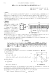
developed by the manufacturer. Example:
|A0»A<®Tftn»Sn>»5<'"^ AP 94 I*" "'"h
approximately equal at every step 2M A X t e s t fi e l d s h o u l d b e n e a r - o - a C K . a t z t
readings of approx. 1.20 or higher
depending on ttie type of paper
The minimum density test held gives an
Example: A graph of a typical test restr-t
('brownish' blacks, not enough Cyan;
mdicadon of contamination, oxidation or
uver-activity of the developer.
The m;;iximiim density test field may
indicate developer and bieachfix errors.
1
m
Low readings may indicate low developer
temperature or ccncentratiDn, short
developing time or developer depletion.
—♦—tOOY
paper and chemicals manufacturer.
—W—LogMj
—4—LoflC :
IT ■
For compiece intormaoon, consult your
1
1
-1
fl o p
0
*1
slop
*2
Moq
Your own control strip
Manufacturer's control strips are excellent
to test your chemicals, but they do not
test your paper, or the combination of your
pr-esent batch of paper with the chemicsls
you are using. The best soluDon is to make
your ov/n control strip for a professional
We advise to do this test with new paoeanri chemicals and store the test resuits
Repent the test whenever you doubt ycur
paper and chemicals, and compare the
readings. Also compare the whites, to
detect contamination.
check, after catibrabng ^ur paper with the
grey test negative.
How to make your own control strip
1. After obtaining a perfect grey testprint.
insert the grey testnegative again.
2. Analyse end adjust the lens at least 2
Imbalances ("crossed curves') can be
caused by ageing of the paper or by
chemical problems. These errors cannot
be eliminated by correction filtering, and
lead to variations m the color balance
between light and dark areas of the print
stops down from maximum aperture (i.e.
f:8).
3. Adjust your eniarger height until the
exposure time reads 5 seconds.
4. Now expose a test strip in 4 parts, each
time covering the other parts and your
Paper reprogram log
For various reasons it is advisable to keep
track of the paper calibration values that
white reference. The exposures are made
you obtain from doing the Reprngram
procedure. A large increase of the Ova'...e
(10 points or more) is a warning that your
with:
developer is becoming oxidised or
a) the correct lens aperture (f:8)
depleted.
b) one stop less light (f: 11 ]
c) one stop more light (f:5.51
d) two stops more light {f:4)
After processing the strip looks like this-
Tast your studio lights
If you are shooting transparencies -n a
studio you may want to check the influence
of the studio lights to review the need for
correction filtering. We suggest that you
take a reference picture of a grey card,
preferably one that has steps from white
to black.
D-MIN
ND
LD
HD
D-MAX
sWhite neutral -Istop +1stQp +2scops
When testing the densities, all greys
should be neutral. The readings for LogY
and LogM and LogC should be
1 4
1, After processing, mssrt it in your
eniarger, (white light - lens npen).
Focus, and test it as follows:
2. Select POS process (p.30). and start
the densitometer hjnction ('ANALYSE]
Read the white step and null the
densitometer with the ANALYSE key
T X 4 R n - M
3. if the white step is not transparent, it
is better to take the slide out and null
nn the white light.
4, Next, test the grey steps. The LogY-MC vafues should be almost equal at
every step, espsciaily in the middle
Color temperature balancing
With the probe diffuser installed, measure
with the probe towards the light source.
For measuring daylight or bright studio
light you need to insert the daylight
reducer into the probe diffuser:
!*eg-nn.
^ the togY-iM and -C values show large
■J fferencss. you may consider to use
c a m e r a c o r r e c t i o n fi l t e r s . I n o r d e r t o
estab'i^ the correct filters, test a grey
step in the middle region, and try different
filters on top of the probe, until Che Y-M-C
readings beccme equal. Then use these
niters m front of your camera lens for
p.cture taking.
Testing your fiim developer
Control strips for testing your film
developer are available from
manufacturers. After processing, they can
be inserted in ^ur enlarger for testing,
and compared to the original developed by
the manufacturer
Your own fiim test strip
Even when shooang on CQlor negative film.
it is good practice to take one shot of a
grey step card, as described above, to
check your studio lights, your exposure
meter, and the film development.
Insert the film in the enlarger and
measure the projecton with the spot
• Set the Y and M Master values to ADO
• Select an unused channel and sec Y to
578 end M to 564,(for daylight film"')
.
Press
A N A LY S E
T h e C o l o r S t a r n o w i n d i c a t e s w h i c h fi l t e r s
are required. Hold correction filters in
front of the probe diffuser, increasing the
filters in strength until the star is nulled.
1. If Y and M LEDs light up, use amber
(yellowish) conversion filters or Y * M
fi l t e r s .
2. If M and C LEDs light up. use bluish
conversion filters or M + C filters.
The filters that are found in this manner
should be used in front of the camera lens
(or the light source). Avoid using too many
filters in frtint of the camera lens.
probe as follows:
• For testing color negatives, Status M
densitometry is required. This is
obtained by setting to NEC [n.OO).
• Null on an unexposed end of your fiim
(the him mask)
• Then read the grey test fields in the
lest negative.
Again, for properly balanced negatives it is
necessary that the LogY-MC readings are
not too different from each other. 18%
grey should read approximately 0.60 (plus
or minus 0.10 is acceptable]. Camera
correction filters may be calculated, but
this IS more difficult than for transparency
film, since the filters work in the opposite
d i r e c t i o n . Yo u a l s o n e e d t o o v e r c o r r e c t .
since negative film is 'soft'. If your light
source is confanuous (not flash) it is easier
to check at the source, using the Colorscar
30C0 as a color temperature meter.
T>:«3fK>15
']For tungsten film 3200K:
Y- 6 3 0
M-590
For tungsten film 34CXDK;
Y=622
S6
INFLUENCE
OF
M-5a6
DARKROOM
SAFEUGHT
While analysing with the color analyser you
can leave the yellow safelight on. but it
should be Indirect, and of low intensity.
With black and white measuring, you may
use yellow or red safelight.
In order to check whether the safelight
influences the readings, especiaily at long
exposure times, cover the safelight
momentarily while analysing, and observe
j whether this influences the Color Star
i nulling or the exposure time reading.
15
27 TROUaLE-SHOCmfSSG
i START HERE
1, Connect and switch the power on.
Are the display and panel lights on ?
Ye s i
V
2. Press the LAMP key several umes.
Does the enlarger lamp switch on and off ?
3. Press the ANALYSE key (LED 18 ON).
Do you see Color Star LEDs lighting up ?
4. Analyse with the probe under the enlarger.
Can you null the Star LEDs with the fitters ?
5. Does the exposure time on the display change
with the lens aperture ?
6. Are the Color Star Y. M or C LEDs blinking on
and off ?
7. Press * EXPOSE [temperature reading)
Is the correct temperature displayed?
18.
Calibrate channel 1 (see step-by^tep instr.)
I Do you get a neutral grey print ?
9. Calibrate channels 4 and 5 for semHntagrated
measuring grey and warm (with Autoprogram,
see st0p43y-step instructions).
Do you get good prints of your own negatives,
using one of these channels ?
CONGRATULATIONS
28 TROUBLE-SHOOTING
PROCEDURES
(A) NO POWER
Te cofTftct mains voicags iS
r-wsa*""..
(L) Y-M VALUES OUT OF RANGE
Press the * key 2 and 3 times and check
the Y and M channel values. Start with
Y- 6 0 0 a n d M = 5 5 0 .
The cotal range is 0. .. 999. Values below
apprax. 400 end above 750 can prnbably
not be nulled by your enlarger filters
IB} BROKEN FUSE (100 mA}
"-.sfi (16) and ^piace if broken.
to BROKEN FUSE (6.3 A, SLOW)
fuse (17) and replace if broken
(0) POWER CORD FAILURE
Zbeck tbe power cnrd and mains plug for
~os^ connections or broken wires.
[E} ENLARGER CORD FAILURE
Check the enlarger cord and socket {or
plug) for loose connections or broken
wires {The power and eniarger cords are
combined m several versions).
(M) D- VALUE OUT OF RANGE
Press the * key 4 times and check the D
(Density) channel value. Adjust D in
between 500 and 550 for your first test.
The total range is O... 999. Values below
approx. 30O will result in 0.0 exposure
time. Values above approx. 800 wilt result
in more than 999 seconds, displaying:
O.FI
(Overflow)
(N) NOT ENOUGH LIGHT
This signal alerts that the aniount of light
on the probe is insufficient for accurate
(FJ ENLARGER FAILURE
1. Check if the enlarger is connected and
measuring. Open the lens wider, or choose
another measuring method.
switched on.
2. Connect the enlarger directly to a
power outlet to check if It works.
3. Or connect the cord of another (amp to
the Coiorstar socket and check If it
does light up.
(0) PAPER CALIBRATION FAILURE
1. Fill out the form 'Setting-up your
CCLORSTAR 30CX3" . including your
reprogramming results and test print
density readings.
2. Mad or fax us a copy.
(G) BLACK-AND-WHITE SELECTED
Press the * key 5 times to cneck the
paper type setting (at black/white setbng
b.OO the star will not light up).
3. Also send the Log sheet (if used] and
(H) NEG/POS INTERCHANGED
[PI PROBE CHANNEL FAILURE
Press the * key 5 times to check the
paper type setting:
n.OO for color negatives, or
P.30 for transparencies,
(!) PROBE NOT CONNECTING
Pull the probe cord plug out and push it in
the sensor connector again.
tJ] PROBE WIRES BROKEN
Have the probe cord and plug checked for
broken wires. Or try another probe, if
available.
(KJ WHITE LIGHT SELECTED
Check if the "white light" switch of the
enlarger is in "filter" position.
rx4SGi7
other data you consider relevant
This enables us to evaluate the cause of
your calibration problems.
The correct operation of the probe
amplifier channels can be tested as
follows;
^. Analyse with the test negative, at full
aperture, and null l^e Color Star (12)
with the enlarger filters.
2. Gradually close the aperture. The first
LED may light up of one or two color
rows, but in general the color balance
should be maintained, until the end of
the range (which is indicated by LEDs
blinking).
If the Color Star shows a significant
change, one of the probe channels is
probably defective or needs recatibraiiun
The probe should be returned for repair
If the color balance is maintained con^ecUy.
the probe is probably not defective.
1 7
TROUBLE-SHQOTiNG PROCEDURES
(CONTINUED]
c. Pressing the * key again displays a
figure 2, and * again: the second calib
(Q) PROBE FILTER FAILURE
d. Continue this until all 5 values are
ration value.
The color filter characteristics of the probe
are factory tested, and errors rarely
entered correctly.
e. You may rotate all numbers with the *
occur. However, all doubts can be
key to check them, and then confirm
Gliminated by testing the quality of the
color analysis as follows:
l a m p / e n d k e y.
and end the calibration with the
(S) developer CONTAMINATION
• Each negative must be analysed with
semi-integrated measuring.
This requires that a channel is calibrated
fur chis method. The cast also vi/arks if the
calibration is not 100% accurate.
o All 4 negatives must be printed
together on one sheet of 20x25 cm
(print size approx. 9x12 cm),
• This sheet must be developed, without
cutting it. if you want to send this sheet
m for cur evaluation we need to receive
!t m one piece.
Test your paper and chemicals by making
a control strip. Follow the procedure "How
to make your own control strip' in
paragraph 25 of the Users" Manual.
Observe if the white is not contaminated.
Test if the black is not brown, and the light
and dark greys do not have an opposite
color shift. All this will show in the quality
of your prints.
The analyser can correct for overall color
shift, but it cannot bring your chemicals
back to strength
if the sheet shows equal color balance and
density for at! prints (at least at the
analysed areas), the probe has accurately
copied the 'test' color.
This may not be the correct color. But
after improving the Y-M-D (channel or
master] calibration all prints will be of the
m MEMORY ERROR
All channel values and calibration dat5 are
stored in an EEPROM memory chip.
The data in the chip may become
disrupted in rare cases. Possible causes
a r e :
same correct color and density.
However, if the 4 prints are clearly
o A power cut or electrical interference,
occurring while you are doing calibration
different from each other, the probe is
steps or changing the channel,
o When, in order to change the paper
probably at fault, and must be returned for
inspBcbon and repair. We appreciate
receiving your comments and examples
With the repair shipment.
(R) PROBE CAUBRATION ERRORS
The probe calibration values, indicated on
a label at the bottom of each (spot or
easel) probe, are entered into the analyser
memory. An error in the first value results
in incorrect temperature readings (with
type setting, one presses the ♦ key
while switching the power OFF.
Praes the ^ key only while switching the
power ON.
The following message is displayed if a
memory error is detected:
E (Error)
EXPOSE). Check the entries as follows and
The fDliowing data are affected;
1. The probe calibration values.
correct them it necessary:
2. Oiibration values of the A-D converter.
3. The paper type setting, the channel
First switch the power off.
values and the master values.
a. Hold the ANALYSE key down, while
switching the power switch (3) on A
figure 1 is displayed.
b. Press thie key (10) The display now
reads the first calibration value, a
number of approx. 500. It may be
changed with the UP and DOWN keys
Ask your distributor for assistance. The
reset procedure is in the service manual.
It can be executed by any technical-minded
person.
29 SPECIFICATIOWS OF THE COLORSTAR 3000 COLOR AftlALYSER
SPOT PROBE
Spot probe for color and black and white.
For spot reading 4 and 6 mm. semnntcgrated
{57 mm] and integral measuring.
AWALYSER FUNCROWS
(VQ f.rj ii' tiS-sC
Averages filtration and exposure time, for
a maximum of 8 tast points.
Memory for measuring with and wrthout negative,
in order to analyse for very lat^e print sizes.
I-ens IOmeter range
-.99 to 9.99 Log Density and Log Y-M-C
Due to technical differences, the test results are not
exactJy equal to other densitometers.
"riper Grflde readings (for B&W]
0 to 5 in steps of 0.5.
T Dmpcraoire measunng
Reads probe temperature in steps of approx. 0.3
degrees Celsius.
Paper t>pe selection
Color negative process, color slide process and
black and white.
Siopc correction
.00 to .35 in steps of .05, [Adjusts the Log exposure
multiplier bet^/een 1.00 and 1.35)
Program channels
0 channels •¥ Master channel
Programming range for Y, M and Density 0 to 999 (9.99 Log). For each channel individually
Master range for Y, M and Density
0 to 99 (Non-nal value = 50) Influences all channels.
Aulu-prograrn
Automatic calibration of 1 channel, using a 'known'
negative-
Rcprogram
Automatic recalibration of 1 channel or of the 'Master'
values, using a test print of the gray negative or slide.
Color Star display
3x4 L£Ds. The first CEOs show the colour balance
within 1 cc. Each subsequent LED: + 4cc.
T I M E R S P E C I F I C AT I O N S
exposure omer
0.1 to 999 seconds. Countdown display and beeper
Interrupted exposures are passible.
AutC' Lamp-off
Enlarger lamp is switched off automatically after 5 mm
ELECTRICAL SPECIFICATIONS.
Mams voltage
Enlargcr load
M a x . 7 0 0 VA a t 11 7 Vo l t s o r 1 3 O 0 VA a t 2 2 0 Vo l t s
1 0 0 - 1 2 0 o r 2 0 0 - 2 4 0 Vo t t s A C . 5 0 - 6 0 H z .
Fuses
100 mA and 6.3 A (Slow): 5 x 20 mm.
Power consumpbon
6 VA
DIMENSIONS
KHyiioartj
(iruba
Cord lengths (approx j
155 X 155 mm Height 63 mm,
76 X 76 X 23 mm.
Probe cord 2 meters. Power cord 2.4 meters.
B f c —
Setting^p your COLORSTAR 3000
Read the STEPSYSTEP INSTRUCTION, and enter your data below:
« Temperature reeding; Your own thermometer reads:
o
The
paper
that
you
are
going
to
use
is:
—
« The paper type selection is: n.OO / p. 30 / b.OQ or other:
o You have preset channel 1 to these values: Y M D
o Your first grey-test print reads: LogD LogY LogM LogC
If this testprint is not neutral grey, use Che reprogram procedure, and record your results:
Reprogramming results tn these values Your next testprint reads these densities:
Y
M
D
LogD
LogY
LogM
LogC
9 If you use only one batch of paper, you can use the Master channel to correct for paper
batch and developer change.
"i jf you use different batches of paper, you can set up one or more channels for each
batch, and use the Master channel to correct for changes in the chemicals.
Keep track of the Master value changes on the Log sheet.
COLORSTAR 3000 Programming
Enlarger Select
Function
Settinp I Function
Execute
Select n-p-b with V
Power On
Paper Type
I
LAMP/END
Select .00 to .35 with A
Select ch. 1 ...8 with A or V LAMP/END j
Channel Nr.
LAMP/END
Change v^th A and V
i Y-M-0 Channel
j Values
LAMP/END
Paper Type
indication
LAMP/END
Change with A and
Y- M - D M a s t e r
Va l u e s
' LAMP/END
With 'known'
Autoprogram
Make
Te s t P r i n t
negative; ANALYSE
s e t fi l t e r s
Place probe on test point
A and A and V together
Before
removing the
probe
Star is nulled
and aperture
Set exposure time with
A and V keys
Insert grey
test negative ANALYSE
Probe centrally under lens
(use appropriate device)
Expose test
or slide
Null star with filters
stnp
Adjust aperture for 5 sec.
(partly white]
" LAMP off
White test:
Density
test
on
T est Print
No negative ANALYSE
ANALYSE/STORE 0.00 (Lamp/End)
White light
Read grey or colour iLogO ^ j
Lens open
LogY ^ LogM ^ LogC
Neutral approx. 0.55
(Slide print: approx. 0.45]
(Not replacing probe):
Reprogram
Density test
Continued
A (« ch.r) for channel or
(= a.r]For Master,
then A and V keys together
LAMP/END
CQU^tm 3000 0|Mfatlon
^
[Select
< Function »Sett^ [Function
Execute
iFosm
Lamp toggles on/off
LAMP
End
Use ▲ and ▼ keys
[Socexpoara
;liO»
;&^xs8
LAMP off
EXPO^ (START)
May be
ended with
LAMP/END
LAMP off
1 Iftterniptpd
exposure
EXPOSE - EXPOSE - EXPOSE
(START-STOP. START)
Seeper
While exposing Beeper on/off with ♦ key
Analysing
A N A LY S E
Oioose test point
NuH star with fitters
Adjust lens aperture
Analysing with
averaging of
tRSt points
White light
(an open
May be
ended with
L A M P^/ E N D 1
LAMP/END
before
replacing the
probe
A N A LY S E
At each point*
LAMP/END
ANALYSE/STORE
before
lens is
After staring last point:
permitted]
Null star with fllte^
repladng
probe
Adjust lens aperture
Analysing with
a reference
White light
Lens open
A N A LY S E
With negative:
LAMP/END
ANALYSE/STOF€
before
Without neg; AT together
replacing
Nut! mar with fitters
probe
Adjust lens aperture
Contrast and
Grade
Lens may be
open for a
♦ ANALYSE
better view
Light area:
ANALYSE/STORE
Dark area: read Contrast or
LAMP/END
Grade, the T key
Temperattre
TX49023
♦ EXPOSE
Probe temperature in "*0
LAMP/END