1
InfoSight
LabeLase 1000 Vector Tag Printer
ITM29663, Service Manual
This manual is intended for qualified service technicians only.
Revision 0
March 2012
INFOSIGHT CORPORATION
20700 U.S. Highway 23
P.O. Box 5000
Chillicothe, Ohio 45601 USA
+1-740-642-3600 Phone (M-F 8am-5pm US Eastern Time Zone)
+1-740-642-4666 Emergency Service (outside normal business hours)
+1-740-642-5001 Fax
www.infosight.com
Copyright © 2003-2012 InfoSight Corporation All Rights Reserved
Page 1 of 46
COPYRIGHT
Copyright 2003-2012 INFOSIGHT CORPORATION
All rights reserved, Printed in U.S.A.
First Printing: March 2012
INFOSIGHT CORPORATION reserves the right to make changes in specifications and other information
contained in this manual without prior notice, and the reader should consult INFOSIGHT
CORPORATION to determine whether any such changes have been made.
In no event shall INFOSIGHT CORPORATION be liable for any incidental, indirect, special, or
consequential damages whatsoever (including but not limited to lost profits) arising out of, or relating to
this manual or the information contained in it, even if INFOSIGHT CORPORATION has been advised,
knew, or should have known of the possibility of such damages.
INFOSIGHT CORPORATION expressly warrants the equipment manufactured by it as set forth in the
Standard Terms and Conditions of Sale. INFOSIGHT CORPORATION makes no other warranties,
either expressed or implied (including without limitation warranties as to merchant ability or fitness for a
particular purpose).
InfoTag, LabeLase and PermaLabel are registered trademarks of InfoSight Corporation.
Producer, HotTag and X-Tag are trademarks of InfoSight Corporation.
Windows is a registered trademark of Microsoft Corporation.
Tesa is a registered trademark of Tesa Tape, Inc.
.
Copyright © 2003-2012 InfoSight Corporation All Rights Reserved
Page 2 of 46
Optical/Laser Safety
INVISIBLE LASER RADIATION
AVOID EYE OR SKIN EXPOSURE TO
DIRECT OR SCATTERED RADIATION
CLASS 1 LASER PRODUCT, USING
A CLASS 4 EMBEDDED LASER (5 W, 10.57 – 10.63 µm)
The laser beam Exits the Final lens 5 inches from the tag
Never attempt to operate the Laser Tag Printer without the protective covers in place.
Never attempt to override any of the safety interlocks on the tag printer.
Never attempt to dismantle or repair the tag printer. In case of malfunction, contact an InfoSight service
representative.
Any of the actions mentioned above may result in permanent eye or skin damage. Refer to Laser Safety
(page 37) for more information on laser safety.
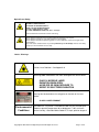
Labels / Warnings
Caution, Laser Radiation – See Appendix A
Warning label located on the front and top of the main cover:
CLASS 4 INVISIBLE LASER
RADIATION WHEN OPEN
AVOID EYE OR SKIN EXPOSURE TO
DIRECT OR SCATTERED RADIATION
Warning label located above the rating plate on the back of the Laser
Marker:
CLASS 1 LASER PRODUCT
Environmental
Conditions
The LabeLase® Tag Printer is intended for Indoor use only. Altitude up to
6500 feet, operating temperature 40 to 100 degrees F, 80% maximum
relative humidity, rated 100-240Vac 50/60 HZ, 5 Amps, pollution degree 2
Copyright © 2003-2012 InfoSight Corporation All Rights Reserved
Page 3 of 46
CAUTION
If this printer is not used in the manner specified by this manual,
the safety features provided may be insufficient.
FUME EXTRACTION SAFETY INFORMATION
When printing on flexible film material, a fume extractor must be used to remove noxious gasses
generated by the laser “burning” the film. The printer includes a port for attaching the
appropriate hoses. It also includes the capability to automatically start the fume extractor.
Customers are able to operate any fume extractor with this printer. InfoSight recommends the
purchase of a filter system (Part # 100-LF) from Filtronics for this purpose.
Copyright © 2003-2012 InfoSight Corporation All Rights Reserved
Page 4 of 46
SOFTWARE/FIRMWARE LICENSE AGREEMENT
IMPORTANT: THE SUBJECT PROGRAMS ARE LICENSED BY INFOSIGHT CORPORATION TO
END-USERS FOR THEIR USE ONLY ON THE TERMS BELOW. ACCEPTING AND USING THESE
PROGRAMS INDICATES YOUR ACCEPTANCE OF THESE TERMS. THIS IS A LEGAL
AGREEMENT BETWEEN YOU, THE END USER, AND INFOSIGHT CORPORATION.
1) GRANT OF LICENSE. INFOSIGHT CORPORATION ("INFOSIGHT") agrees to grant to you a nonexclusive license to use the INFOSIGHT software/firmware program (the "PROGRAM") subject to the
terms and conditions of this license agreement.
2)
DEFINITION OF TERMS. The term SOFTWARE refers to a computer program stored on
CDROM, floppy diskette, hard disk, magnetic tape, paper tape or other media that must be loaded into the
computer's memory to be executed. The term FIRMWARE refers to a computer program stored in
semiconductor memory (ROM, PROM, EPROM, EEPROM, NVRAM, etc.) that is an integral part of the
computer's memory. Together, these forms of computer programs are referred to as the "PROGRAM".
3)
COPYRIGHT. The PROGRAM(s) and Documentation are owned by INFOSIGHT and are
protected by United States copyright laws and international treaty provisions. The PROGRAM(s) contain
trade secrets and proprietary property of INFOSIGHT. You may make one copy of the PROGRAM(s)
solely for backup or archival purposes provided that the copy clearly displays the INFOSIGHT copyright
notice. Additional copies may be made when authorized to do so in writing by INFOSIGHT. In addition
to any other right of INFOSIGHT, INFOSIGHT has the right to terminate this license if the terms of this
license are violated.
4)
RESTRICTION ON USE AND TRANSFER. The single-processor version(s) of the PROGRAM(s)
and Documentation are to be used on one computer or embedded system at any one time. The multiprocessor version(s) of the PROGRAM(s) and Documentation may be used over a network provided that
the number of computers accessing the network simultaneously shall not exceed the number authorized by
INFOSIGHT or for which you paid the corresponding multi-processor fee. You may not distribute the
PROGRAM(s) or Documentation to a third party. You may transfer the license and complete package
(retaining nothing) if the transferee agrees to the terms of this License Agreement. Neither the
PROGRAM(s) nor the Documentation may be changed or translated without express written permission
of INFOSIGHT. You may not reverse engineer, decompile or disassemble the PROGRAM(s).
5)
WARRANTY for the subject PROGRAM(s) is covered under the INFOSIGHT STANDARD
TERMS AND CONDITIONS OF SALE.
6)
TERM. The license is effective until terminated. It may be terminated if you fail to comply with
any term or condition of this License Agreement. You may terminate this License Agreement at any time.
In the event of termination, you agree to destroy the PROGRAM(s) and Documentation together with all
copies and related material.
7)
YOUR USE OF THIS PROGRAM(S) acknowledges that you have read this License Agreement and
agree to its terms. This agreement is complete and supersedes any other agreement that may have related
to the subject matter of this agreement.
Copyright © 2003-2012 InfoSight Corporation All Rights Reserved
Page 5 of 46
PREFACE
The LabeLase 1000 Vector Tag Printer is fourth in the family of InfoSight laser tag printers. The
LabeLase 1000 series contains many new features, including: a higher internal processor clock speed, a
PC-driven interface and the ability to print multilingual fonts. The LabeLase 1000 Vector Tag Printer
includes the capability of printing on flexible film material and cutting through the top layers of the film
to create “peel and stick” self-adhesive labels.
This OPERATIONS AND MAINTENANCE manual is intended as a companion to the ONLINE
REFERENCE MANUAL supplied with the Producer software and also available on the web at
http://www.infosight.com/labelaseproducer/index.htm
This OPERATIONS AND MAINTENANCE manual will be automatically installed on your computer’s
hard drive when installing the Producer software. It may be found under the PROGRAMS’ menu with
other INFOSIGHT software and HELP files.
MINIMUM SYSTEM REQUIREMENTS
IBM PC 100% compatible computer.
Pentium 400 MHz.
Windows 2000/XP(32bit)/Vista(32bit)/7(32bit & 64bit)
(** Windows 95/98/NT are no longer supported for LabeLase 1000 and Producer applications).
80MB available disk space.
64MB RAM
1 communications port for connection to the printer (serial, USB or ethernet depending on the
communications option provided on the printer).
Color monitor (800x600 resolution or higher recommended).
CD or DVD drive.
LabeLase 1000 firmware version LL1000 v1.07 or higher.
LabeLase Producer version 1.61 or higher.
Copyright © 2003-2012 InfoSight Corporation All Rights Reserved
Page 6 of 46
TABLE OF CONTENTS
TITLE
Copyright Information
PAGE
2
Optical / Laser Safety / Fume Extraction
3-4
Software / Firmware License Agreement
5
Preface
6
Minimum System Requirements
6
Index (this page)
7
Printer Setup
Software Installation
8
8
Install Spool Arm Assembly
9
System Connections & Power-Up
10
Printer Communications
Installing USB Drivers
11
12
Startup Sequence
16
Loading New Metal Tags
Loading New Flexible Film Material
17
18
Preparing To Print: Using a Vacuum Fume Extractor
19
Printing a Metal Tag
Printing a Flexible Film Label
21
22
LabeLase® Producer™ Software
Traditional & Vector Tag Setups
Printer Configuration & Laser Settings
23
24
25
Cycle Time Considerations
26
Best Practices and Helpful Hints
28
Basic Troubleshooting
29
Normal Maintenance & Servicing
Lens Cleaning Procedure
Air Filter Removal and Replacement
Cleaning the Internal Drive Mechanism
Fuse Replacement
30
30
31
32
33
Customer Service
34
Functional Block diagram
35
Serial Port Connections
35
Declaration of Conformity
36-37
Appendix A | Laser Safety
38-41
Drawings and Parts Listings
42-46
Copyright © 2003-2012 InfoSight Corporation All Rights Reserved
Page 7 of 46
PRINTER SETUP
The LabeLase 1000 Vector Tag Printer requires 100-240 VAC, 50/60 Hz, 5 A.
NOTE: both sides of the incoming line voltage are fused. See the Maintenance section for
instructions on replacing fuses.
The LabeLase Vector 1000 Tag Printer should be positioned so that the power supply cord exits from the
back of the machine.
The LabeLase 1000 Vector Tag Printer should be placed in a temperature controlled environment. This
printer, though designed for industrial use, should be treated as any typical computer system and printer.
Dirty environments will necessitate a more frequent cleaning schedule for internal optics.
If the printer is housed in a secondary protective enclosure, the two exhaust fans located on the bottom of
the printer directly underneath the tag feed drive area must not be obstructed. Ideally the fans should be
exhausted to the environment outside the enclosure, with clean & dry makeup air entering the enclosure
toward the back of the printer near the foam element air filter.
A 12-foot (3.6 meter) RS-232 serial communications cable is provided for communicating with your
Windows-based PC. A USB cable is also provided with the optional USB/ethernet communications
module. See the serial connector wiring diagram at the back of this manual for additional information if
another serial cable is required.
The LabeLase 1000 Vector Tag Printer should be positioned near the chosen fume extractor. The hoses
should be properly attached. An outlet exists on the back of the machine intended to power the fume
extractor. The outlet for the fume extractor is rated at 3 amps. Plug the fume extractor power cord into
this outlet.
SOFTWARE INSTALLATION
Before connecting the printer to your PC, LabeLase Producer software should first be installed on your
PC.
The easiest way to install the software is to use the Installer Disk that came with your new printer. In
addition to installing the correct version of LabeLase Producer for your specific printer model, it will also
allow you to configure the appropriate communications interface. In most cases this will allow you to skip
the Printer Communications and USB Drivers sections of this manual.
If your original Installer Disk is not available, the latest release of Producer software can also be
downloaded directly from http://www.infosight.com/labelaseproducer.htm . This is a self-contained,
single self-installing file. However, it will not automatically guide you through the configuration process
for communications, and you must therefore follow the steps outlined in the Printer Communications and
USB Drivers sections of this manual.
Copyright © 2003-2012 InfoSight Corporation All Rights Reserved
Page 8 of 46
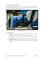
INSTALL SPOOL ARM ASSEMBLY
The LabeLase 1000 Vector Printer requires a spool arm assembly to be installed on the printer. The
flexible film material is supplied on a larger spool. The spool arm assembly provides more space for the
material. All required parts are included with the printer.
Step 2
Step 4
Step 3
Spool Shaft
Spool Arm Assembly
Assembly Instructions
1. Layout all parts of spool arm assembly: vertical arm section, horizontal arm section, shaft, 6
screws, one bolt.
2. Connect the vertical arm section and the horizontal arm section with four screws.
3. Connect the vertical arm section to the LabeLase 1000 Vector Tag Printer with two screws at the
base.
4. Connect the vertical arm section to the LabeLase 1000 Vector Tag Printer with one bolt in the
middle of the arm section.
5. Connect the shaft to the horizontal arm section by screwing it in. The photo shows flexible film
material loaded onto spool shaft. The material and keeper bar will not be on the shaft during this
assembly.
Copyright © 2003-2012 InfoSight Corporation All Rights Reserved
Page 9 of 46
SYSTEM CONNECTIONS & POWER-UP:
1. Attach the included RS-232 cable from the LabeLase
1000 Vector Printer to your Windows-based PC running
LabeLase Producer software.
2. Insert the AC power cord of the fume extractor into the
provided outlet.
3. Insert the AC power cord into a nearby power receptacle.
NOTE: both sides of the incoming line voltage are
fused. See the Maintenance section for instructions on
replacing fuses.
4. Place the security key into rear of machine. The key
functions as an ON-OFF switch.
5. Turn the key to the vertical (ON) position. NOTE: The
security key can only be removed when in the OFF
position.
6. Press the power switch to the ON position (1).
Optional USB & Ethernet
connectors. See following section
of this manual for instructions on
installing required drivers.
NOTE: rear panel layouts may
vary, depending on the printer
configuration
Copyright © 2003-2012 InfoSight Corporation All Rights Reserved
Page 10 of 46
PRINTER COMMUNICATIONS
The LabeLase 1000 series of printers require a communication link to a PC running LabeLase Producer
software. In addition to the standard serial RS232 link, an optional integrated USB/Ethernet module is
available.
The LabeLase Producer software defaults to a serial port on COM1 and automatically configures the port
settings. If your computer has a communications port other than COM1, you can select that port from the
LabeLase Producer main menu, SETUP…PREFERENCES…TAG PRINTER COMMUNICATIONS
(note: Supervisor login is required). Select the appropriate port from the pull-down list.
If you are uncertain about which port to use, more details about each communication port are available in
the Device Manager in the Windows Control Panel.
Copyright © 2003-2012 InfoSight Corporation All Rights Reserved
Page 11 of 46
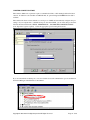
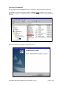
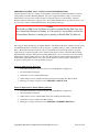
INSTALLING USB DRIVERS
If your printer includes the USB/Ethernet option, you will need to install the appropriate drivers first.
The USB driver is found on the Producer installation CDROM. Explore the disk (do not use the Auto
Run feature), navigate to the installation directory, and run SETUP.EXE. This will run the VCP Installer
program.
When the VCP Installer has finished, click the Finish button.
Copyright © 2003-2012 InfoSight Corporation All Rights Reserved
Page 12 of 46
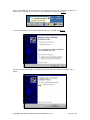
Next, plug the USB cable into an available port on your PC and into the back of the LabeLase 1000 Vector
Printer. Power on the printer and you will see a New Hardware message for the Adapter.
Followed immediately by the Found New Hardware Wizard for the USB Serial Device:
Install the software automatically as recommended. When the Wizard has finished installing, click on
Finish.
Copyright © 2003-2012 InfoSight Corporation All Rights Reserved
Page 13 of 46
Next you will receive a Found New Hardware message for the USB Serial Port
Followed immediately by the Found New Hardware Wizard for the USB Serial Port:
Install the software automatically as recommended. When the Wizard has finished installing, click on
Finish.
Copyright © 2003-2012 InfoSight Corporation All Rights Reserved
Page 14 of 46
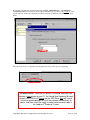
Now return to the LabeLase Producer main menu, SETUP…PREFERENCES…TAG PRINTER
COMMUNICATIONS, and select the newly added communications port which will probably be at the
bottom of the list. If in doubt, check the list of Ports in the Device Manager in the Windows Control
Panel
The printer will now be recognized by LabeLase Producer and you may proceed to print tags.
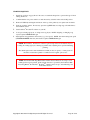
SPECIAL NOTE: Once the first printer is installed, each time you
connect a new printer to your PC, the Found New Hardware Wizards
for both the USB Serial Device and the USB Serial Port will launch.
Follow the guided prompts to install the software automatically as
above, and then select the newly installed communications port in
the LabeLase® Producer™ menu.
Copyright © 2003-2012 InfoSight Corporation All Rights Reserved
Page 15 of 46
STARTUP SEQUENCE:
1.
Install tag stock onto tag payoff reel. Be sure to re-attach the keeper bar to prevent the tag roll from
falling off the reel.
2.
Confirm that the rear power switch is on and the rear key switch is in the vertical ON position.
3.
Remove E-STOP by twisting the red button on the top of the printer by one-quarter turn clockwise.
4.
Feed tag stock into printer. If necessary, press the tag FEED button to align tags or flexible film to
the breakoff location.
5.
Start LabeLase Producer software on your PC.
6.
Load a pre-existing tag layout, or design a new tag layout. NOTE: designing or changing a tag
layout requires SUPERVISOR login.
7.
Adjust printer setup parameters if necessary (e.g., laser speed). NOTE: other than setting laser speed
(LIGHTER/DARKER slider bar), this feature requires SUPERVISOR login.
NOTE: The LabeLase® Producer™ software is password protected for all features beyond
loading an existing tag layout, entering tag variable data, adjusting laser speed and initiating
printing.
The default password for new installations is blank (no data, no spaces). A new password
should be created before printer is commissioned for regular operator use.
NOTE: For Flexible Film Tag Material the vacuum extractor must also be set up to start
running before tags are printed. If the vacuum extractor is powered by the LabeLase 1000
Vector Tag Printer, the LabeLase® ProducerTM software can be set up to automatically power
on the fume extractor.
Copyright © 2003-2012 InfoSight Corporation All Rights Reserved
Page 16 of 46
LOADING NEW METAL TAGS
CAUTION: DO NOT GRIP THE TAG STOCK BY ITS EDGES WHEN FEEDING
INTO THE PRINTER. PROTECT YOUR HANDS AND FINGERS FROM THE
SHARP EDGES OF THIN METAL TAG STOCK AT ALL TIMES.
Loading a new roll of metal tags is as easy as mounting the new roll on the payoff reel so that it unwinds
from the bottom, and hand-feeding the leading edge of the tag stock into the rear feed slot. The marking
side of the tag stock should be facing UP. Gently push it into the slot until it stops against the internal
(rear drive) roller. The printer will then automatically draw the tag stock into the printer. Do not use a
wrench to tighten the keeper bar.
Keeper Bar
Tag Reel
Reminder - The marker is not ready for use and will not feed tags until the E-STOP
button is returned to the OUT position by twisting the red button one-quarter turn
CLOCKWISE.
If necessary, tag stock can be manually fed into the printer by pressing the FEED button located beside the
large red E-STOP button.
NOTE: The function of the FEED button on top of the printer has changed with
Firmware version 1.03 and later.
Press & Release Quickly = feed one tag-length OUT (forward).
Press & Hold for 1 Second = feed one tag-length IN (reverse).
Press & Hold for longer than 2 Seconds = CONTINUOUS REVERSE FEED.
Copyright © 2003-2012 InfoSight Corporation All Rights Reserved
Page 17 of 46
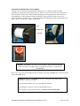
LOADING FLEXIBLE FILM TAG MATERIAL
Loading a new roll of flexible film tag material requires the use of a chuck provided by the film
manufacturer. The chuck is placed inside the spool. The spool can now be mounted on the payoff reel so
that it unwinds from the bottom. Hand-feed the leading edge of the tag material into the rear feed slot.
The marking side of the tag material should be facing UP. Gently push it into the slot until it stops
against the internal (rear drive) roller. The printer will then automatically draw the tag material into the
printer. Do not use a wrench to tighten the keeper bar.
Chuck
Keeper Bar
Tag Reel
Reminder - The marker is not ready for use and will not feed tags until the E-STOP
button is returned to the OUT position by twisting the red button one-quarter turn
CLOCKWISE.
If necessary, tag stock can be manually fed into the printer by pressing the FEED button located beside the
large red E-STOP button.
NOTE: The function of the FEED button on top of the printer has changed with
Firmware version 1.03 and later.
Press & Release Quickly = feed one tag-length OUT (forward).
Press & Hold for 1 Second = feed one tag-length IN (reverse).
Press & Hold for longer than 2 Seconds = CONTINUOUS REVERSE FEED.
Copyright © 2003-2012 InfoSight Corporation All Rights Reserved
Page 18 of 46
PREPARING TO PRINT TAGS – USING VACUUM FUME EXTRACTOR
LabeLase Producer Software is capable of automatically operating the Vacuum Fume Extractor needed
when printing on Flexible Film Tag Material. The power supply (maximum 3 amps) to the Vacuum
Fume Extractor chosen by the customer should be connected in the rear of the machine. LabeLase
Producer Software is then able to supply power to the Vacuum Fume Extractor only when necessary. It is
not necessary to run the Vacuum Fume Extractor when printing metal tags.
Caution:
The LabeLase 1000 Vector Tag Printer is capable of printing Flexible Film Tags when
no Vacuum Fume Extractor is running. It is the operator’s responsibility to ensure the
Vacuum Fume Extractor is running prior to printing on Flexible Film Tag Material.
The setups for metal and film tags are slightly different. The LabeLase Producer Software will turn on the
Vacuum Fume Extractor and run it for 10 seconds prior to printing a film tag. This is called the Filter
Delay. The LabeLase Producer Software will also automatically reverse feed tag material to properly
align metal tags for their start print location and the break-off point. This is called Auto Reverse Feed.
The Filter Delay should be disabled before printing Metal Tags, as it is not necessary to run the Vacuum
Fume Extractor when printing metal tags. The Auto Reverse Feed should be disabled when printing on
flexible film tag material because its use could cause the material to jam the printer. Instructions to
properly set up the printer for each tag material are below:
Printer Configuration for Metal Tags
1.
In the LabeLase Producer Software Screen, select Setup/Printer Configuration:
2.
Select the Printer Config Tab.
3.
Check the box next to Disable Filter Delay.
4.
Uncheck the box next to Disable Auto Reverse Feed (thus enabling Auto Reverse Feed).
5.
Print tags according to directions below: PRINTING A METAL TAG.
Printer Configuration for Flexible Film Tag Material
1.
In the LabeLase Producer Software Screen, select Setup/Printer Configuration:
2.
Select the Printer Config Tab.
3.
Uncheck the box next to Disable Filter Delay (thus enabling the Filter Delay).
4.
Check the box next to Disable Auto Reverse Feed.
5.
Print tags according to directions below: PRINTING A FLEXIBLE FILM TAG.
Copyright © 2003-2012 InfoSight Corporation All Rights Reserved
Page 19 of 46
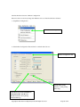
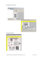
LabeLase Producer Screens for Printer Configuration:
Please note these screens may change with different versions of LabeLase Producer Software.
1. Setup/Printer Configuration:
Select Printer Configuration
2. Select Printer Configuration Tab and check or uncheck desired boxes:
Printer Configuration Tab
Disable Filter Delay:
Check box when printing
Metal Tags
Don’t Reverse from Tear-Off Before
Print (Or Disable Auto Reverse
Feed): Check Box when printing
Flexible Film Tags
Copyright © 2003-2012 InfoSight Corporation All Rights Reserved
Page 20 of 46
PRINTING A METAL TAG
Note - The following assumes the LabeLase 1000 Vector Tag Printer has already been setup with a tag
layout.
There are several ways to print a tag using the LabeLase 1000 Vector Tag Printer.
A) If metal tag stock is loaded in the machine from the rear payoff reel and properly aligned at the
break off exit point:
1. Pressing the PRINT button located beside the red E-STOP will initiate printing of 1 or
more tags, depending on operator-entered data on the main LabeLase Producer screen.
2. Pressing the F12 key on your PC.
3. Placing the mouse pointer over the Begin Print button on your PC and left clicking.
4. A print command may be sent from your host computer to your PC via Extended
Protocol.
B) If there is no metal tag stock feeding in from the back of the machine, a single tag inserted in the
FRONT slot will be automatically drawn into the printer.
1. If the AUTO PRINT SINGLE ITEMS box is checked (enabled) in the SETUP /
PRINTER CONFIGURATION menu (requires supervisor login), then tag printing will
begin automatically with no further action or input required.
2. If the auto print box is NOT checked, then any of the above methods in paragraph (A)
may be used to initiate printing.
CAUTION: DO NOT GRIP THE TAG STOCK BY ITS EDGES WHEN FEEDING
INTO THE PRINTER. PROTECT YOUR HANDS AND FINGERS FROM THE
SHARP EDGES OF THIN METAL TAG STOCK AT ALL TIMES.
NOTE: The SINGLE PRINT feature of the printer requires a minimum tag or
tag-strip length of three inches (76mm).
For example, a single 3x3 (or 3x4, 3x6, etc) tag may be printed. If single
printing of a 3x1 (76 x 25mm) tag is desired, a strip of at least 3 tags must be
inserted in the front slot.
Copyright © 2003-2012 InfoSight Corporation All Rights Reserved
Page 21 of 46
PRINTING A FLEXIBLE FILM TAG
Caution:
The LabeLase 1000 Vector Tag Printer is capable of printing Flexible Film Tags when
no Vacuum Fume Extractor is running. It is the operator’s responsibility to ensure the
Vacuum Fume Extractor is running prior to printing on Flexible Film Tag Material.
Note - The following assumes the LabeLase 1000 Vector Tag Printer has already been setup with a tag
layout.
1.
2.
3.
4.
5.
6.
Flexible Film tag material is loaded in the machine from the rear payoff reel and properly aligned
at the break off exit point.
In the LabeLase Producer Software screen, select Set Up/Printer Config from the Menu Bar.
Pressing the PRINT button located beside the red E-STOP will initiate printing of 1 or more
tags, depending on operator-entered data on the main LabeLase Producer screen.
Pressing the F12 key on your PC.
Placing the mouse pointer over the Begin Print button on your PC and left clicking.
A print command may be sent from your host computer to your PC via Extended Protocol.
NOTE: The SINGLE PRINT feature of the printer requires a minimum tag or
tag-strip length of three inches (76mm).
For example, a single 3x3 (or 3x4, 3x6, etc) tag may be printed. If single
printing of a 3x1 (76 x 25mm) tag is desired, a strip of at least 3 tags must be
inserted in the front slot.
Copyright © 2003-2012 InfoSight Corporation All Rights Reserved
Page 22 of 46
LABELASE PRODUCER
SOFTWARE
LabeLase Producer is an integrated, Windows-based application for complete control of tag design and
printing. For complete details, please refer to the ONLINE REFERENCE MANUAL supplied with the
software, or on the web at http://www.infosight.com/labelaseproducer.htm
Features:
The software has many features designed to provide maximum flexibility to serve the customer’s specific
marking needs. Some of these features include:
Built-in and online (web access) HELP.
Total freedom to change tag layout whenever needed.
WYSIWYG (“What You See Is What You Get”) user interface for simple and intuitive tag
design.
New features emulating popular presentation software packages to speed layout and organization
of complex designs containing multiple text and graphic fields.
An unlimited number of data, text, barcode and graphic fields.
Move fields easily with drag-and-drop.
Rotate fields in 90-degree increments.
Unlimited UNDO-REDO to easily correct mistakes.
Optional placement grid with snap-to placement aid.
Optional field anchor display shows field alignment.
Zoom in/out for detailed display.
Tag geometry features such as holes, slots, bare edges and bend lines can be shown.
Tag geometry feature for vector cuts of peel-off flexible film tags can be shown.
Prints all PC-installed fonts, including multi-byte characters for Asian languages.
User-selectable download of message data from a host computer via RS-232, network TCP/IP, or
network file transfer. A wide selection of communication protocols includes InfoSight
Extended, emulation of Zebra and Intermec standard printers, and simple comma or tabseparated, flat-file formats. Details can be found in the communications chapter of the online
reference manual.
Operator entry of message data, for example if the host computer is unavailable.
Easy control over printer setup parameters such as laser speed (i.e., formerly known as the “heat”
setting for different types of laser tag material) and high/low pixel density (i.e., “draft” and
“normal” printing modes)
Auto-print feature for single tag printing (i.e., whenever a roll of tags is not loaded, a single tag
can be auto-printed simply by inserting the tag in the front tag slot).
Auto-incrementing of all text and number fields, for unattended batch printing.
Option to make text and graphic fields “non-printable”
Option to make non-printable fields visible in the File Open dialog, and on the LabeLase
Producer™ main screen.
Copyright © 2003-2012 InfoSight Corporation All Rights Reserved
Page 23 of 46
TRADITIONAL TAG SETUPS:
VECTOR TAG SETUPS:
Copyright © 2003-2012 InfoSight Corporation All Rights Reserved
Page 24 of 46
PRINTER CONFIGURATION & LASER SETTINGS
The LabeLase® 1000 Vector printer and the LabeLase® Producer™ software are designed with a high
degree of flexibility and user-control, to enable the system to be used in a wide range of applications and
on an ever-increasing array of laser-markable materials.
Calibration and configuration settings are accessed in LabeLase® Producer™ under SETUP-PRINTER
CONFIGURATION. On-line help instructions will guide you through each of the available settings. The
most common parameters for fine-tuning the performance of the printer beyond the easy-to-use
LIGHTER/DARKER SLIDER BAR are LASER SPEED, LASER OFF TICKLE, and LASER ON DUTY
CYCLE, and VECTOR DUTY CYCLE, all of which are found under the LASER tab. Each of these
parameters separately and together can be adjusted to create the right balance of black/white contrast,
fineness of detail and cycle time.
As laser speed is increased printing cycle time will be faster. In general, as laser speed increases, duty
cycle must also be increased to achieve the same relative blackness. Some materials with especially
sensitive surfaces, such as PermaLabel®, will print more consistently at lower duty cycles, and therefore
correspondingly lower laser speeds. Tickle controls the readiness of the laser to fire and helps maintain
consistency of marking across the tag surface. Some tag materials are more sensitive to power variation
than others, but in most cases this parameter can be left at its factory setting.
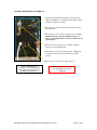
Typical Range of Settings (DRAFT mode OFF):
• Laser Speed: 50-75 ips
• Laser Off Tickle: 7-15 µs
• Laser On Duty Cycle: 60-95%
• Laser Vector Duty Cycle: 35%
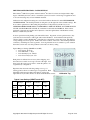
Each printer is calibrated in our factory before shipping, and
the results are recorded on two tags as shown at the right. Save
these tags in the event you ever want to return the printer to its
original factory configuration.
Experience has shown the following settings to be a good
starting point for the most common types of tag material. Each
individual application may then be fine tuned to achieve the
right balance of cycle time, fineness of detail, and black/white contrast.
Calibration Tag
Typical Laser Settings (DRAFT mode OFF)
Hot Tag™
Pic-Anneal®
PermaLabel®
X-Tag™
Laser
Speed
70
60
55
20
Tickle
15
15
15
15
Duty
Cycle
95%
95%
95%
95%
Factory Settings
Copyright © 2003-2012 InfoSight Corporation All Rights Reserved
Page 25 of 46
CYCLE TIME CONSIDERATIONS
Tag layout and printer configuration can have a significant influence on cycle time. Here are a few
techniques that in many cases can significantly speed printing.
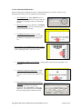
1.
Select DRAFT mode. When DRAFT mode is on,
stepper and mirror resolution, laser speed, font sizes,
and barcode and graphic scales are automatically
adjusted.
2.
Increase laser speed (move slider bar to LIGHTER).
It may be necessary to increase Laser Duty Cycle to
maintain black/white contrast.
3.
Use ARIAL BLACK font for text, to create
darker easier-to-read characters. Also try using
the BOLD font setting instead of a larger font
size.
Design printing to run ACROSS the tag at 90° rotation
(right angles to tag feed) rather than down the tag at 0°
rotation (printing parallel to tag feed is slower).
4.
Avoid drawing graphic boxes around text or other graphics with long vertical (parallel to tag
feed) lines.
5.
Combine text strings into fewer lines. A single
long line of text is more efficient than several
short lines of text (at 90° rotation, parallel to tag
feed).
6.
Keep graphics/logo X-scale and Y-scale factors
equal to 1. If the graphic or logo must be resized to fit on the tag, use an external
application such as MS PAINT to change the
dimensions of the image and re-save the BMP
file before importing into LabeLase Producer.
Copyright © 2003-2012 InfoSight Corporation All Rights Reserved
Page 26 of 46
7.
Typical Vector Duty Cycle setting is 35%. If the cut is
too deep (the laser cuts through all layers, including
backing) reduce 1-2% at a time. If the cut is too
shallow (the label does not peel off the backing, increase
1-2% at a time.
Copyright © 2003-2012 InfoSight Corporation All Rights Reserved
Page 27 of 46
BEST PRACTICES AND HELPFUL HINTS
To facilitate sharing of best practices among users, InfoSight has created an online DISCUSSION
FORUM. You may access the forum via our home webpage or directly at
http://www.infosight.com/forums/ .
Copyright © 2003-2012 InfoSight Corporation All Rights Reserved
Page 28 of 46
BASIC TROUBLE SHOOTING
Service during normal business hours (Monday-Friday, 8am-5pm):
+1-888-642-3600 or +1-740-642-3600
Emergency after-hours service: +1-800-401-0716 (outside the USA call +1-740-642-4666)
Red LED Status Light:
STEADY ON: ready to print.
OFF: no power to laser (power cord, key switch, power switch, fuses).
SLOW BLINK: out of tag stock.
FAST BLINK: E-STOP.
Problem: Marker does not respond to print button.
Check power cord.
Check key switch.
Check E-STOP.
Check tag stock.
Check serial cable to PC.
Producer software must be running on the connected PC.
Bottom of main LabeLase Producer screen indicates printer status – “ONLINE”, “ESTOP” or “UNKNOWN
MODE”. If UNKNOWN MODE, check communications cable and settings.
From within LabeLase Producer, click on HELP-ABOUT. If the FIRMWARE VERSION is blank, your PC
does not see the printer. Check communications cable and settings.
Problem: Out of tag message on PC screen.
Load more tag stock into printer.
Insert single tag in front tag slot.
Problem: Tag exiting too far or not far enough (breakoff “nick” not aligned with exit slot).
The printer may need to be re-calibrated. See the Troubleshooting & Maintenance / Feed and Tag
Adjustment section of the built-in help.
Problem: Tag print appears very light, fine lines appear to drop out.
Reduce laser speed (DARKER)
Increase Laser Off Tickle (SETUP-PRINTER CONFIGURATION).
Final output lens may require cleaning (see Maintenance section below).
Problem: Tag print shows “shadows”
Decrease Laser Off Tickle (SETUP-PRINTER CONFIGURATION).
Problem: Tag print not aligned correctly with breakoff “nicks” (leading & trailing edges).
Check that actual tag size in machine and programmed tag size in Producer (LAYOUT-SETUPGEOMETRY) are the same.
The printer may need to be re-calibrated. See the Troubleshooting & Maintenance / Feed and Tag
Adjustment section of the built-in help.
Problem: Barcode too long for tag size.
Reduce number of characters in barcode data.
Use more efficient barcode symbology.
Reduce barcode scale.
Problem: Flexible Film Tag Material Does not peel off from backing
Increase Vector Duty Cycle
Problem: Flexible Film is cut entirely through the backing
Decrease Vector Duty Cycle
Copyright © 2003-2012 InfoSight Corporation All Rights Reserved
Page 29 of 46
NORMAL MAINTENANCE & SERVICING
The only regular maintenance required is periodic cleaning of both surfaces of the final pass-through lens
to remove dust, and cleaning or replacing the rear air filter. Additional cleaning or maintenance requires
removal of the laser cover, contact InfoSight for instructions.
LENS CLEANING PROCEDURE
CAUTION: LASER OPTICS ALIGNMENT SHOULD ONLY BE
PERFORMED BY A QUALIFIED TECHNICIAN.
The lens slide is secured with a SECURITY TORX
screw to prevent unintended opening.
After removing the security screw, carefully open
the slide to expose the lens.
Carefully perform the cleaning procedure described
below, then re-insert the lens slide and secure it with
the security screw.
CAUTION: DO NOT TOUCH LENS WITH FINGERS OR ANY SUBSTANCE
CONTAINING ALCOHOL, OR PERMANENT DAMAGE MAY RESULT.
LENS CLEANING PROCEDURE:
Use a cloth that will not leave any fibers and is not abrasive.
White vinegar is recommended. DO NOT USE ALCOHOL!!
Gently wipe the moistened cloth across the lens so that the liquid evaporates behind the cloth,
avoiding streaks.
DO NOT RUB HARD!
DO NOT USE COMPRESSED AIR TO CLEAN OPTICS!
DO NOT USE EYE GLASS WIPES CONTAINING ALCOHOL!
For optics that are severely contaminated or damaged, contact InfoSight for replacement.
Copyright © 2003-2012 InfoSight Corporation All Rights Reserved
Page 30 of 46
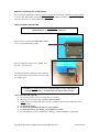
AIR FILTER REMOVAL & REPLACEMENT
The LabeLase® 1000 Vector Printer includes a light-duty foam filter element, intended for use in a normal
office environment. It is not intended to protect the printer from industrial contaminants or vapors,
typical of a factory or mill environment.
As the filter element accumulates dust and pollen over time, air flow through the printer may be reduced.
This may cause excessive dust to accumulate on the internal optics (lenses and mirrors), which may
shorten their life considerably. Therefore, it is important to monitor the condition of the filter and
determine the appropriate cleaning frequency for your specific environment.
At high duty cycles when printing large batches of tags with a high percentage of black (printed) area,
reduced air flow may also cause the internal temperature sensor to automatically shutdown the laser tube
until it cools back to its normal operating temperature – this is normal.
The filter cover is located on the rear
of the printer, and is held in place
by two thumb screws.
Loosen the thumb screws and carefully remove the
cover and the foam filter element underneath.
Carefully blow any lint or dust off the filter, or
gently wash it in soap and water. Dry the filter
thoroughly before reinstalling.
Copyright © 2003-2012 InfoSight Corporation All Rights Reserved
Page 31 of 46
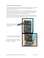
CLEANING THE INTERNAL DRIVE MECHANISM
In some environments with excessive ambient dust, limited airflow through the printer and high rates of
operation, dust and debris may collect in the drive mechanism area of the printer. Over time this dust and
debris may block the laser beam and/or affect the operation of internal sensors and drive rollers.
CAUTION: ALWAYS UNPLUG BOTH THE PRINTER POWER CORD AND
ALL COMMUNICATION CABLES BEFORE SERVICING THE DRIVE UNIT.
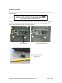
The front cleanout plate may be removed to clean the drive mechanism without removing the printer
cover. Extreme care must be used to avoid damaging laser optics, pass-through lens, optical tag & notch
sensors, and other delicate components. The pass-through lens should be left in place to avoid
introducing dust into the laser optics.
A soft brush or long Q-Tip can be used to loosen any debris, and a small PC keyboard vacuum with a 90degree or flexible nose piece can be used to remove the loosened debris.
The front cleanout plate is secured with two
SECURITY TORX screws to prevent unintended
opening
REAR NOTCH SENSOR
FRONT TAG SENSOR
Laser Beam hits the tag between Front and
Middle drive rollers. Dust may collect at the
extreme left and right-hand sides of this area.
CAUTION: ALWAYS REPLACE THE FRONT CLEANOUT PLATE BEFORE
CONNECTING POWER AND OPERATING THE PRINTER.
NEVER OPERATE THE PRINTER WITH THE FRONT CLEANOUT
PLATE OR THE PASS-THROUGH LENS REMOVED!!
Copyright © 2003-2012 InfoSight Corporation All Rights Reserved
Page 32 of 46
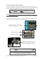
FUSE REPLACEMENT
The incoming AC line is fused on both legs. Before replacing the fuses, first determine and fix the cause
of the blown fuses.
CAUTION: BE SURE TO REMOVE THE AC POWER CORD BEFORE
REMOVING THE FUSE HOLDER OR PERFORMING ANY OTHER
TROUBLESHOOTING OR MAINTENANCE!
To replace the fuses, remove the fuse holder on the back of the printer between the power cord input and
the on-off rocker switch. The fuse holder only goes back in one-way. If it does not fit easily, turn it
upside down and then insert it gently so that it snaps in place.
FUSE HOLDER
FUSE HOLDER REMOVED
FUSES ARE RATED FOR
250V / 5A AC
Copyright © 2003-2012 InfoSight Corporation All Rights Reserved
Page 33 of 46
CUSTOMER SERVICE
How to reach customer service:
Phone Support
InfoSight Corporation Customer Service offers free phone support to answer
questions during normal non-holiday working hours, Monday through Friday
8am to 5pm Eastern time (New York, USA).
Call +1-888-642-3600, or outside the USA call +1-740-642-3600.
Emergency Service
After regular business hours or holidays, call +1-800-401-0716
Outside the USA call +1-740-642-4666.
On-Site Service
InfoSight Corporation can dispatch a Field Service Engineer to your facility to
perform equipment start-up, repair, maintenance, and training.
Service Contracts
Periodic scheduled on-site maintenance, technical service and extended
warranties can be arranged by contacting Customer Service at the number
below.
Factory Service
Call Customer Service for a Return Authorization Number before returning
equipment to our factory for repair and/or major maintenance.
For more information regarding any of these services, call +1-888-642-3600 (outside the USA call +1740-642-3600) and ask for Customer Service.
Or, visit us on the worldwide web at www.infosight.com
Copyright © 2003-2012 InfoSight Corporation All Rights Reserved
Page 34 of 46
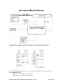
Functional Block Diagram
LABELASE 1000 SERIAL PORT CONNECTION TO AN IBM-PC OR EQUIVALENT.
Note: Handshake protocol is XON / XOFF. Communications adapters such as USB to RS232
must support XON / XOFF.
XON is DC1 CTL-Q or 11h or 17 decimal
XOFF is DC3 CTL-S or 13h or 19 decimal
Copyright © 2003-2012 InfoSight Corporation All Rights Reserved
Page 35 of 46
Declaration of Conformity
InfoSight Corporation
20700 U.S. Highway 23 Chillicothe, Ohio 45601
+1-740-642-3600 PHONE +1-740-642-5001 FAX
InfoSight herby declares the equipment specified conforms to the Classification(s), Directive(s)
and Standard(s) set forth in this document.
InfoSight produces laser systems within one of two classes as identified and classified by the
CDRH. These are Class I and Class IV. (See CDRH 21 CFR (J) 1040.1 - 1040 .5). End user of
the equipment should be familiar with ANSI, CDRH and OSHA standards for radiation emitting
devices as they apply to them also.
ANSI Z136.1 - 1993
We will provide adequate data to the LSO (Laser Safety Officer) enabling LSO to designate NHZ
(nominal hazard zone) as required pursuant to Class IV 3.4.1
CDRH 21 CFR (J) 1040.1 1040.5
OSHA Publication 8-1.7
Section II Chapter 6
Certifications:
EMC Emissions
EN 55022:1994/A1:1995/A2:1997 Class A ITE emissions requirements (EU)
FCC 47 CRF Part 15 Class A emissions requirements (USA)
EMC Immunity:
EN 50082-2:1995 EMC heavy industrial generic immunity standard
Note: InfoSight design guidelines are drawn from ANSI and CDRH
Copyright © 2003-2012 InfoSight Corporation All Rights Reserved
Page 36 of 46
1.1.1 LL1000 Declaration of Conformity
Declaration of conformity
Konformitätserklärung
Déclaration de conformité
Declaración de Confomidad
Verklaring de overeenstemming
Dichiarazione di conformità
We/Wir/ Nous/WIJ/Noi: InfoSight Corporation
20700 U.S. Highway 23
Chillicothe, Ohio 45601 USA
declare under our sole responsibility that the product,
erklären, in alleniniger Verantwortung,daß dieses Produkt,
déclarons sous notre seule responsabilité que le produit,
declaramos, bajo nuestra sola responsabilidad, que el producto,
verklaren onder onze verantwoordelijkheid, dat het product,
dichiariamo sotto nostra unica responsabilità, che il prodotto,
LL1000
to which this declaration relates is in conformity with the following standard(s) or other normative
documents.
auf das sich diese Erklärung bezieht, mit der/den folgenden Norm(en) oder Richtlinie(n) übereinstimmt.
auquel se réfère cette déclaration est conforme à la (aux) norme(s) ou au(x) document(s) normatif(s).
al que se refiere esta declaración es conforme a la(s) norma(s) u otro(s) documento(s) normativo(s).
waarnaar deze verklaring verwijst, aan de volende norm(en) of richtlijn(en) beantwoordt.
a cui si riferisce questa dichiarazione è conforme alla/e seguente/i norma/o documento/i normativo/i.
EMC Emissions:
• EN 55022:1998/A1:2000/A2:2003 Class A ITE emissions requirements (EU)
• FCC 47 CFR Part 15 Class A emissions requirements (USA)
EMC Immunity:
• EN 55024:1998/A1:2001/A2:2003 ITE - immunity characteristics
1.2 TEST DATES
November 18, 22-24, 29, 30, December 1, 8, and 9, 2004
Edward S. ONeal
2/25/2005
Chillicothe, Ohio
Copyright © 2003-2012 InfoSight Corporation All Rights Reserved
Page 37 of 46
APPENDIX A | LASER SAFETY
LASER SAFETY
04/23/03
Section I: Introduction to Laser Safety
Lasers, like arc welders, are sources of intense light that require certain precautions to insure a safe,
comfortable and compliant working environment. This is especially true since the laser included in this
marking equipment operates in the infrared (invisible) portion of the light spectrum. The enclosure
surrounding the marking area is designed to prevent human exposure to the light emitted by the laser. The
following information covers the procedures taken to design a safe, efficient environment for laser marking
equipment.
Laser products are categorized into one of four classes based upon the power of the laser light that is
accessible to any person during normal operation. These classes range from Class 1, the lowest class
requiring no additional safeguards other than those provided by the manufacturer, to Class 4, the highest
class that requires additional operator and working environment safeguards for safe operation.
Class 1 laser marking systems include enclosures integral to the workstation that are constructed to
prevent human access to the laser beam. Class 1 systems are safe in all working environments; they are
installed and operated as any other industrial machine tool. Class 1 laser systems do not require the use of
any special laser safety equipment by operators or bystanders during their normal operation.
Class 4 laser marking systems do not incorporate protective enclosures. Extra precautions are required.
The LabeLase 1000 Vector Printer complies with Class 1 during normal use because of the numerous
interlocks provided as detailed in section II.
During service and/or alignment the LabeLase 1000 Vector Printer becomes a Class 4 device. Servicing
should be performed only by a Qualified Laser Service/Safety Technician! Because of the Class 4
classification, InfoSight will provide such a person to be available to the end user of this marker.
The nominal power output of the laser used is 10 watts, with a maximum peak power output of 30 watts. It
is a C02 infrared (invisible) laser with a wavelength of 10.57 to 10.63 microns. The Radiant energy and the
wavelength are less than Class 1 requirements during normal operation.
Section II: Types of safety interlocks.
There are several types of safety features provided on the InfoSight LabeLase 1000 Vector Printer:
Type 1 includes mechanical switches. These switches are located atop the marker and on the rear of
the marker. These switches remove power supplied to the laser marker, as shown in electrical drawings.
Switch A -- Large Red, easily accessible, E-STOP operator Emergency Stop Push Button.
Switch B -- Key switch
Switch C -- On/Off rocker switch
Type 2 includes optical sensors. Sensors monitor whether tag material is in place and the marker is able
to move the tag material. These two sensors are monitored by the marking microprocessor.
Type 3 includes mechanical design. Here, narrow slots are provided to minimize the release of laser
radiation. The beam path from laser tube to final pass through lens is entirely enclosed in a metal shield,
with suitable material that will absorb the heat produced by the beam emitting from the CO2 laser.
Type 4 includes Password Security access. The Software requires a supervisor password to change
layout of tags or to alter the operating parameters of the marker itself.
The features and precautions described above are designed with the safety of the user in mind. Should you
have any questions or suggestions please contact InfoSight directly.
Copyright © 2003-2012 InfoSight Corporation All Rights Reserved
Page 38 of 46
LASER HAZARD CLASSIFICATIONS
The intent of laser hazard classification is to provide clear distinction of the lasers’ properties and hazards to users so
appropriate protective measures can be taken. Classification is based on the maximum output available for the intended use.
Specific labeling requirements indicate that the class of the laser as well as the emission wavelength(s) and any other
applicable precautionary instructions must be included on any signage. Laser classification is also used for determining
requirements for medical surveillance for those individuals working with and around lasers.
The Federal United States laser safety standard [21 CFR 1040.10], the ANSI standard [ANSI Z136.1], as well as the
international standard [EN 60825], divide lasers into five distinct hazard categories. These classes are based upon the
combination of wavelength range, power, and emission duration, which are used to determine the level of risk and the potential
to cause biological damage to the eye or skin. The definitions compiled from ANSI Z136.1 are as follows:
Class 1: Any laser, or laser system containing a laser, with wavelength ranges from Ultraviolet through Far Infrared (180 nm
– 100,000 nm +), that cannot emit laser radiation levels exceeding Class 1 Accessible Emission Limits (AEL) as defined by
ANSI Z136.1. For example this would compute to exposure (for an eight-hour period) for a 488 nm laser of no greater than 0.2
mW. Basically, the laser radiation level emitted by a device classified as Class 1 produces no hazard whatsoever to the user
during normal operation. Presently, Class 1 lasers and laser systems are exempt from all control measures. The Class 1
designation does not apply during times of maintenance or service where the safety controls of the device are defeated or
otherwise removed. The Class 1 environment resumes once the device is returned to its original state with all safety devices
properly reconnected.
Class 2: This classification applies only to continuous wave (CW) and repetitive-pulse lasers and laser systems of the visible
part of the electromagnetic spectrum (400 – 700 nm) that exceed Class 1 levels, but do not exceed an average radiant power
of 1 mW.
Class 3a: Lasers and laser systems that have an accessible output between one and five times the Class 1 AEL for
wavelengths shorter than 400 nm or longer than 700 nm, or less than five times the Class 2 AEL for wavelengths between 400
and 700 nm. Lasers of this class have intermediate power ranges of 1 - 5 mW.
Class 3b: Lasers and laser systems having the power range between 5 - 500 mW. This applies to lasers with wavelength
ranges from Ultraviolet through Far Infrared (180 nm – 100,000 nm +). These lasers or laser systems can produce a hazard if
viewed directly, and may produce an eye hazard when viewing diffuse reflections off of a shiny surface at angles of less than 5
degrees from the source, however Class 3b lasers should not produce a hazardous diffuse reflection from a matte (not shiny)
surface.
Class 4: Lasers and laser systems having power greater than 500 mW. This applies to lasers with wavelength ranges from
Ultraviolet through Far Infrared (180 nm – 100,000 nm +). This class of laser poses the greatest hazard, and any and all
precautions should be taken to protect oneself from exposure to direct or diffuse laser radiation. Direct exposure to the eye
from this class of laser can cause permanent damage. Stray beams are potential fire hazards and combustible material should
be kept out of beam paths at all times.
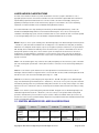
1.3 CONTROL MEASURES FOR LASER CLASSIFICATIONS
Control
M easure
Class 1
Class 2
Class 3a
Activation
Warning
Systems
No requirement.
No requirement.
No requirement.
Should have.
Shall have.
Indoor Laser
XE Optics
No requirement.
No requirement.
No requirement.
Shall have.
Nominal Hazard
Shall have. Nominal
Hazard Zone
Copyright © 2003-2012 InfoSight Corporation All Rights Reserved
Class 3b
Class 4
Page 39 of 46
Lasers
Controlled Area
Zone analysis
required.
analysis required.
Labels
Shall have
Shall have
Shall have.
Shall have.
Shall have.
Area Posting
No requirement.
No requirement.
Should have
Shall have.
Nominal Hazard
Zone analysis
required.
Shall have. Nominal
Hazard Zone
analysis required.
Standard
Operating
Procedures
No requirement.
No requirement.
No requirement.
Should have.
Shall have.
Education and
Training
No requirement.
Should have.
Should have.
Shall have.
Shall have.
Authorized
Personnel
No requirement.
No requirement.
No requirement.
Shall have.
Shall have.
Warning Signs
and Labels
No requirement
Should have.
Should have.
Shall have.
Nominal Hazard
Zone analysis
required.
Shall have. Nominal
Hazard Zone
analysis required.
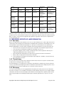
ANSI Z136.1 requires specific control measures for each laser classification and the environment in which they are used. The
chart above lists some of the requirements that may need to be implemented in a laboratory setting. The company Laser Safety
Officer, or designee, should reference the applicable safety regulations for appropriate control measures to implement in the
area the marker will be used.
1.4 BIOLOGICAL EFFECTS OF LASER IRRADIATION
1.4.1 Eye Injury
Because of the high degree of beam collimation, a laser serves as an almost ideal point source of intense light. A laser beam of
sufficient power can theoretically produce retinal intensities at magnitudes that are greater than conventional light sources, and
even larger than those produced when directly viewing the sun. Eye exposure to a direct beam can cause permanent eye
damage including blindness. Protective eyewear should always be worn when potential exposure to direct laser beams exist.
Due to the lens-like focusing effect of the human eye, it is 100,000 times more vulnerable to injury than the skin.
Laser safety eyewear should always be available for the wavelengths of lasers in use.
Eye protective equipment, however, should be considered the last line of defense against laser beam exposure –
Remove all jewelry when working with an open beam to prevent reflection of the beam in unsafe directions.
When possible, use all protective housings, interlocks and shields.
Laser Safety Eyewear should always be worn during laser repair, alignment, or installation, or at any time when any
engineering and administrative controls should be used first.
laser safety control is not in place.
1.4.2 Thermal Injury
The most common cause of laser-induced tissue damage is thermal in nature, where the tissue proteins are denatured due to
the temperature rise following absorption of laser energy.
The thermal damage process (resulting in burns) is generally associated with lasers operating at exposure times greater than
10 microseconds and in the wavelength region from the near ultraviolet to the far infrared. Tissue damage may also be caused
by thermally induced acoustic waves following exposures to sub-microsecond laser exposures.
1.4.3 Skin Injury
To the skin, UVA (315-400 nm) can cause hyperpigmentation and erythema (aka: sunburn). Exposure in the UVB (280-315
nm) range is most injurious to skin. In addition to thermal injury caused by ultraviolet energy, there is also possibility of radiation
carcinogenesis from UVB. The shorter wavelengths are absorbed in the outer dead layers of the epidermis (stratum corneum)
and the longer wavelengths have an initial pigment-darkening effect followed by erythema if there is exposure to excessive
levels.
Copyright © 2003-2012 InfoSight Corporation All Rights Reserved
Page 40 of 46
The hazards associated with skin exposure are of less importance than eye hazards; however, with the expanding use of
higher-power laser systems, particularly ultraviolet lasers, the unprotected skin of personnel may be exposed to extremely
hazardous levels of the beam power if used in an unenclosed system design.
Skin burns caused by lasers can happen quite fast and with great intensity. Protective clothing should be worn when potential
exposure to direct laser beams exist.
UVC: 200-280 nm exposure may cause erythema (sunburn), skin cancer, and burns.
UVB: 280-315 nm exposure may cause accelerated skin aging, increased skin pigmentation and burns.
UVA: 315-400 nm exposure may cause pigment darkening and skin burns.
Visible: 400-700 nm exposure may cause photosensitive reactions and skin burns.
Infrared 700-100,000 nm exposure may cause skin burns.
Copyright © 2003-2012 InfoSight Corporation All Rights Reserved
Page 41 of 46
DRAWING ITM27742 – LABELASE 1000 VECTOR COVER ASSEMBLY
Copyright © 2003-2012 InfoSight Corporation All Rights Reserved
Page 42 of 46
DRAWING ITM19696F – LABELASE 1000 VECTOR DRIVE ASSEMBLY
Copyright © 2003-2012 InfoSight Corporation All Rights Reserved
Page 43 of 46
DRAWING ITM24439C – LABELASE 1000 VECTOR OPTICS ASSEMBLY
Copyright © 2003-2012 InfoSight Corporation All Rights Reserved
Page 44 of 46
DRAWING ITM27751 – LABELASE 1000 VECTOR BASE ASSEMBLY
Copyright © 2003-2012 InfoSight Corporation All Rights Reserved
Page 45 of 46
DRAWING ITM19870B – LABELASE 1000 VECTOR SPOOL, PAYOFF
GENERAL ASSEMBLY
Copyright © 2003-2012 InfoSight Corporation All Rights Reserved
Page 46 of 46