1
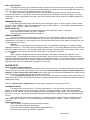
PLEASE – SET – SPEED
Speed reading is erratic or
jumps around.
Speed reading is incorrect.
Gauge lights up, but tach
will only show zero.
Speed sensor is not being turned
by transmission.
Sensor is not sending a speed signal.
Gauge is not calibrated
Speedometer not calibrated
Speed sensor wire is loose or broken.
Cable is loose or broken.
Poor ground connection.
Ignition Interference
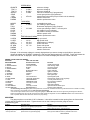
Tach reading is erratic or
jumps around.
Gauge is not calibrated correctly.
Yellow wire is not connected properly.
Ignition system not grounded properly.
Gauge is not grounded properly.
Tach signal type is not set correctly.
Gauge is not calibrated
Tach signal wire is loose or broken.
Poor ground connection.
Tach reading is incorrect.
Gauge will not dim.
Update rate is too fast.
Gauge is not calibrated correctly.
Blue wire is not connected correctly.
Gauge remains dim at all
Blue wire is getting power all of the time.
times.
High beam, Left turn, or Right Loose or incorrect connection to indicator wire.
turn indicator does not work.
Neutral, low oil, or engine
indicator does not work.
Loose or incorrect connection to indicator wire.
speedometer ground.
Check cable connection between sensor and transmission.
Sensor can be tested by spinning the cable with a drill.
Check for a damaged or malfunctioning speed sensor.
Gauge must be recalibrated (see instructions).
Gauge must be calibrated to your vehicle (see instructions)
Check all wire connections and inspect wire for breaks.
Check cable between sensor and transmission.
Check ground connection on speedometer and sensor.
Check for tachometer wires routed with VSS signal wires.
Check for VSS signal wires routed near ignition coils
Check for poor ignition system ground
Use suppression spark plug wires
Gauge must be calibrated (see instructions).
Check connection from yellow wire to tach signal wire.
Check engine and ignition system grounds.
Check gauge and engine grounds.
Change the tach signal type (see instructions).
Gauge must be recalibrated (see instructions).
Check all wire connections and inspect wire for breaks.
Check ground connection on tachometer, engine, and ignition
system.
Reset display update speed slower.
Gauge must be calibrated (see instructions).
Check wiring connections. Blue wire should have 12 volts
with headlights on.
Connect blue wire to location that only has power only when
the headlights are on.
Check that the appropriate indicator wire has about 0 volts
when the indicator should be off and about 12 volts when
the indicator should be on.
Check that the appropriate indicator wire has about 12 volts
when the indicator should be off and about 0 volts when the
indicator should be on.
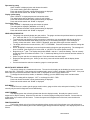
Speed sensor voltage checks. All checks should be made with the sensor connected to the gauge and the key on.
Checks should be done with a voltmeter and not a test light. Checks for the 3-wire sensor should be made between each
individual wire and ground.
3-wire sensor: Red wire should have 9-11 volts dc, slightly less than battery voltage, (sometimes +5V if supplied by
factory harness)
Black wire should show ground, 0 volts dc at all times.
White wire should vary between 0 and 5 volts dc as the gear teeth, or a steel object passes by the sensor.
Aluminum and Stainless Steel will not work with a Hall-effect sensor. This can be checked with the sensor
mounted and spinning the rear tire slowly, or by removing the sensor and moving a steel object pass the
face of the sensor.
2-wire sensor: Measure the voltage between the two sensor wires. With the wheel spinning the voltage should be about
1-10 volts ac (make sure the meter is set to AC volts and not DC volts for this check).
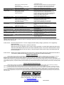
SERVICE AND REPAIR
DAKOTA DIGITAL offers complete service and repair of its product line. In addition, technical consultation is available to help you work through any questions or
problems you may be having installing one of our products. Please read through the Troubleshooting Guide. There, you will find the solution to most problems.
Should you ever need to send the unit back for repairs, please call our technical support line, (605) 332-6513, to request a Return Merchandise Authorization
number. Package the product in a good quality box along with plenty of packing material. Ship the product by UPS or insured Parcel Post. Be sure to include the RMA number
on the package, and include a complete description of the problem with RMA number, your full name and address (street address preferred), and a telephone number where you
can be reached during the day. Any returns for warranty work must include a copy of the dated sales receipt from your place of purchase. Send no money. We will bill you after
repair.
Dakota Digital 24 Month Warranty
DAKOTA DIGITAL warrants to the ORIGINAL PURCHASER of this product that should it, under normal use and condition, be proven defective in material or
workmanship within 24 MONTHS FROM THE DATE OF PURCHASE, such defect(s) will be repaired or replaced at Dakota Digital’s option.
This warranty does not cover nor extend to damage to the vehicle’s systems, and does not cover removal or reinstallation of the product. This Warranty does not
apply to any product or part thereof which in the opinion of the Company has been damaged through alteration, improper installation, mishandling, misuse, neglect, or accident.
This Warranty is in lieu of all other expressed warranties or liabilities. Any implied warranties, including any implied warranty of merchantability, shall be limited to
the duration of this written warranty. Any action for breach of any warranty hereunder, including any implied warranty of merchantability, must be brought within a period of 24
months from date of original purchase. No person or representative is authorized to assume, for Dakota Digital, any liability other than expressed herein in connection with the
sale of this product.
4510 W. 61ST St. N., Sioux Falls, SD 57107
Phone: (605) 332-6513 FAX: (605) 339-4106
www.dakotadigital.com
[email protected]
©Copyright 2004 Dakota Digital Inc.
MAN# 650088B