1
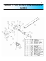
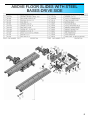
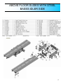
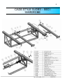
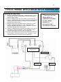
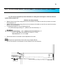
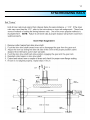
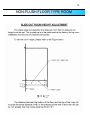
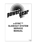
Service & Parts Manual
for GULF STREAMPower Gear Electric
Slide Systems
CONTENTS
1217 E. 7th St.
Mishawaka IN
46544
800-334-4712
fax (574) 256-6743
www.powergearus.com
Page
Before you operate the slide system
2
Operating Instructions
3
Preventive maintenance
3
Manually overriding your slide system 4
Above floor slides with aluminum bases 5
Above floor slides with steel bases
6-7
Cage Style Slides-bed / wardrobe
8
Wiring Diagram-Relay Control
9
Adjustment information
10-11
Synchronizing Rails
12
Motor troubleshooting guide
13
Warranty information
14
2
Before you operate the slide system
The Power Gear electric slide-out system in your coach is designed to give you years of trouble
free operation and reflects the latest state of the art technology. READ, STUDY, AND
UNDERSTAND THIS MANUAL BEFORE OPERATING YOUR SLIDE-OUT SYSTEM.
SYSTEMS DESCRIPTION
Your Power Gear slide-out system is a rack and pinion design operated by a 12Volt DC electric
motor.
MAJOR COMPONENTS
•
•
•
Inner rail assemblies are designed to support the room weight.
The 12Volt DC gear motor will operate the room using power from the onboard unit
battery.
Slide-out systems are equipped with a manual override that allows you to extend / retract
the room in the event of a loss of power.
WARNING
•
•
•
ALWAYS MAKE SURE THAT THE SLIDE-OUT ROOM PATH IS CLEAR BEFORE
AND DURING OPERATION OF THE SLIDE-OUT ROOM.
ALWAYS KEEP AWAY FROM THE SLIDE-OUT RAILS WHEN THE ROOM IS BEING
OPERATED. THE GEAR ASSEMBLY MAY PINCH OR CATCH ON LOOSE
CLOTHING CAUSING PERSONAL INJURY.
ALWAYS UTILIZE A ROOM LOCKING DEVICE ON THE SLIDE-OUT ROOM DURING
STORAGE AND TRANSORTATION.
FAILURE TO FOLLOW THESE INSTRUCTIONS COULD
RESULT IN SERIOUS INJURY OR DEATH.
3
Operating Modes
EXTENDING THE ROOM
1.
2.
3.
4.
5.
Level the unit.
Verify the battery is fully charged and hooked-up to the electrical system.
Remove the transit bars (if your unit is so equipped).
Make sure the room path is clear (both inside and outside the coach).
Check the slide-out awning (some awnings must be manually unlocked before operating
the slide-out).
6. Press and hold the IN/OUT switch in the OUT position until the room is fully extended
and stops moving.
7. Release the switch, which will lock the room into position.
RETRACTING THE ROOM
1. Verify the battery is fully charged and hooked-up to the electrical system.
2. Make sure the room path is clear (both inside and outside the coach).
3. Press and hold the IN/OUT switch in the IN position until the room is fully retracted and
stops moving.
4. Release the switch, which will lock the room into position
5. Check the slide-out awning (some awnings must be manually locked before traveling).
6. Install transit bars (if your unit is so equipped).
Preventative Maintenance
Your Power Gear slide-out system has been designed to require very little maintenance. To ensure
the long life of your slide-out system read and follow these few simple procedures.
CAUTION: DO NOT WORK ON YOUR SLIDE-OUT SYSTEM UNLESS THE BATTERY IS
DISCONNECTED.
•
•
When the room is out, visually inspect the inner slide rail assemblies. Check for excess build-up
of dirt or other foreign material; remove any debris or items that may be present.
If the system squeaks or makes any noises it is permissible to apply a light coating of silicone
spray or lithium grease to the roller and bearing sleeve I.D., removing any excess lubricant so
that dirt or debris do not build-up. DO NOT lubricate the slide-out drive gears, gear racks, or
roller OD as this will attract dirt / debris.
IF YOU HAVE ANY PROBLEMS OR QUESTIONS CONSULT YOUR LOCAL AUTHORIZED
DEALER OR CALL US AT POWER GEAR (800-334-4712)
4
Manually Overriding your Slide-out
Your Power Gear slide-out system is equipped with a manual override that allows you to extend or
retract the room in the event of a loss of power. NOTE: If the room does not move when the
switch is pressed, check the following:
• Battery is fully charged and connected
• The transit bars are removed
• All system fuses/circuit breakers and relays are good.
•
•
•
•
•
•
•
•
Locate the slide-out motor (see drawings later
in this manual). The motor is located in the top
of the center storage compartment under the
slide-out room. For a bedroom slide-out the
motor will be mounted to rail assembly.
Rotate the brake lever on the back of the
motor counter-clockwise (looking from the
rubber boot end of the motor) about 1/8 of a
turn to the released position. Refer to the label
on the motor and the motor drawing in this
manual. This will release the brake that holds
the room in place. The room is now free to
move.
Locate the manual override on the end of a rail
assembly (or on the motor itself). It is also
permissible to use an adjustable wrench on
the square drive shaft to crank the room in or
out (if the room is so equipped).
Check the slide-out awning (some awnings
must be manually unlocked before operating).
Using a ¾ wrench or ratchet, crank the room
either in or out completely (depending on your
need).
When the room is fully in/out apply pressure to
the wrench or ratchet and return the motor
brake lever to the "Engaged" position. This will
ensure the room is locked into a sealed
position.
Check the slide-out awning (some awnings
must be manually locked before traveling).
Install transit bars (if so equipped) and take
the unit to an authorized dealer for service.
!!WARNING!!
WHEN THE MOTOR BRAKE IS DISENGAGED THE SLIDE-OUT ROOM WILL NOT LOCK IN
PLACE; THEREFORE, THE ROOM WILL NOT BE SEALED. WHEN THE ROOM HAS BEEN
MANUALLY RETRACTED, BE SURE TO INSTALL THE TRANSIT BARS AND RETURN THE
MOTOR BRAKE LEVER TO ITS NORMAL “ENGAGED” POSITION IN ORDER TO SEAL AND
LOCK THE ROOM INTO POSITION.
5
ABOVE FLOOR SLIDES WITH ALUMINUM
BASES
ABOVE FLOOR SLIDES WITH STEEL
BASES-DRIVE SIDE
6
ABOVE FLOOR
FLOOR SLIDES
SLIDES WITH
WITH STEEL
STEEL
ABOVE
BASES-IDLER SIDE
SIDE
BASES-IDLER
7
8
CAGE STYLE SLIDES – BED /
WARDROBE
9
TYPICAL WIRING WITH A RELAY STYLE CONTROLLER
Diagnosing the relay control:
1) Measure voltage between B+ and B-. Voltage less than 11.5 volts
is insufficient. Repair or recharge battery or repair wiring before
attempting other repairs.
2) Measure voltage at green wire when switch is moved to the “IN”
position. It should be at least 11.5 volts. Voltage less than specified
indicates a bad switch or wires to the switch. Check seat switch
and park brake switches also.
3) Measure voltage at blue wire when switch is moved to the “OUT”
position. It should be at least 11.5 volts. Voltage less than
specified indicates a bad switch or wires to the switch. Check the
seat switch and park brake switches also.
4) Measure voltage between M1 and M2 when switch is moved to the
“IN” position. It should be at least 11 volts. Less than 11 volts
indicates a bad control if all other steps have been OK.
5) Measure voltage between M1 and M2 when switch is moved to the
“OUT” position. It should be at least 11 volts. Less than 11 volts
indicates a bad control if all other steps have been OK.
**Must be fused per
latest edition of
ANSI/RVIA standard
for low voltage
systems in
conversion and
recreational vehicles.
DN13819
Relay Control
Blue Wire
Green Wire
Red Wire
10
FLAT FLOOR ROOM HEIGHT ADJUSTMENT---FLUSH FLOOR STYLE SLIDES
This TIP sheet is designed to provide information on setting the room height on a flat floor slide-out
system utilizing angled rails.
•
•
•
With the room fully extendedMeasure from the top of the moving slide-out rail to the bottom of the slide-out room floor up close to the coach.
This is dimension “A”.
Measure from the top of the moving slide-out rail to the bottom of the slide-out room floor out near the mounting
bracket. This is dimension “B”.
To calculate dimension “B” use the following formula:
“B” (end bracket height setting)=“A” + (slideout room floor thickness) + ¼”.
EXAMPLE:
“B” (end bracket height setting) =“A” + (slideout room floor thickness) + ¼”.
If “A” = 3-1/4” AND THE SLIDEOUT FLOOR IS 1” THICK
Then “B”=3-1/4” + 1” + ¼” = 4-1/2”
•
Perform this check on each slide-out rail independent of the other.
NOTE:
1) These figures are approximates. Each coach may be slightly different.
2) Refer to manufacturer of coach/trailer for correct slideout room floor thickness.
11
SYNCHRONIZING RAILS
12
NON-FLUSH FLOOR TYPE ROOM
TROUBLE SHOOTING DC-ELECTRIC MOTORS
13
14
Power Gear Warranty Policy
Power Gear warrants to the original retail purchaser that the product will be free from defects in material and
workmanship for a period of (5) years following the retail sales date later than 9-1-05. Labor to repair these
components will be covered for two years. Power Gear will, at its option, repair or replace any part covered by this
limited warranty which, following examination by Power Gear or its authorized distributors or dealers, is found to be
defective under normal use and service. No claims under this warranty will be valid unless Power Gear or its
authorized distributor or dealer is notified in writing of such claim prior to the expiration of the warranty period.
Warranty is transferable pending documentation of original sale date of product.
THIS WARRANTY SHALL NOT APPLY TO:
• Failure due to normal wear and tear, accident, misuse, abuse, or negligence.
• Products which are modified or altered in a manner not authorized by Power Gear in writing.
• Failure due to misapplication of product.
• Telephone or other communication expenses.
• Living or travel expenses.
• Overtime labor.
• Failures created by improper installation of the product’s slideout system or slideout room to include final adjustments
made at the plant for proper room extension/retraction; sealing interface between slideout rooms and side walls;
synchronization of inner rails; or improper wiring or ground problems.
• Failures created by improper installation of leveling systems, including final adjustments made at the plant, or low
fluid level, wiring or ground problems.
• Replacement of normal maintenance items.
There is no other express warranty other than the foregoing warranty. THERE ARE NO IMPLIED WARRANTIES OF
MERCHANTIBILITY OR FITNESS FOR A PARTICULAR PURPOSE. IN NO EVENT SHALL POWER GEAR BE
LIABLE FOR ANY INCIDENTAL OR CONSEQUENTIAL DAMAGES. This warranty gives you specific legal rights, and
you may also have other rights, which vary from state to state. Some states do not allow the limitations of implied
warranties, or the exclusion of incidental or consequential damages, so the above limitations and exclusions may not
apply to you.
For service contact your nearest Power Gear authorized warranty service facility or call 1-800-334-4712. Warranty
service can be performed only by a Power Gear authorized service facility. This warranty will not apply to service at
any other facility. At the time of requesting warranty service, evidence of original purchase date must be presented.
Power Gear
1217 E. 7th Street
Mishawaka, IN 46544
800/334-4712
www.powergearus.com