1
Index
C
:AC:STEP B-15, B-16
:CODE B-4, B-18
:COUNt? B-4, B-18
:DATE B-7
:DATE? B-19
:DC:STEP0 B-16
:INIT B-5, B-19
:LOCK B-5, B-20
:LOCK? B-6, B-8, B-20
:NDUE B-7
:RCOunt B-20
:SAVE B-6, B-21
:STEP0 B-21
:STEP1 B-9
:STEP10 B-12
:STEP11 B-13
:STEP12 B-13
:STEP2 B-10
:STEP3 B-10
:STEP4 B-10
:STEP5 B-11
:STEP6 B-11
:STEP7 B-11
:STEP8 B-12
:STEP9 B-12
A
AC calibration commands B-14
AC characteristics accuracy A-2
AC current A-5
verifying, Model 2700 1-13
AC voltage A-5
verifying, Model 2700 1-10
verifying, Model 7700 1-20
ACA signal switching 4-17
Accuracy calculations A-2
ACV and ACA signal multiplexing and
gain 4-17
ACV and FREQ signal switching 4-15
AMPS input 4-10
Analog circuitry 4-10
block diagram 4-11
Analog signal switching states 4-14
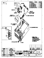
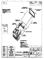
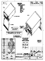
Assembly drawings 5-3
B
battery
replacement 3-6
Calibration 2-1
calibration
aborting 2-6
AC current 2-12
AC voltage 2-11
code 2-4
comprehensive 2-5
considerations 2-3
cycle 2-5
DC current 2-10
DC voltage 2-8
front panel 2-6
front panel short and open 2-7
Model 7700 2-22
Model 7700 and 7706 2-22
preparing the Model 2700 2-6
recommended equipment 2-5
Remote Model 7700 2-23
resistance 2-9
setting dates and saving 2-12
step completion B-24
calibration code
front panel 2-4
remote 2-4
calibration commands
AC B-14
DC B-9
manufacturing B-16
miscellaneous B-4
Model 7700 and 7706 B-17
Calibration error summary B-22
Calibration Reference B-1
Card cage removal 5-5
Case cover removal 5-4
Command summary B-2
Component layouts 6-2
Connections
AC volts calibration 2-11
DC and AC amps calibration 2-10
DC volts and ohms calibration 2-8
Input terminal wire 5-7
manufacturing calibration 2-20
Model 2700 AC current verification 1-13
Model 2700 AC volts verification 1-10
Model 2700 DC current verification 1-12
Model 2700 DC volts verification 1-8
Model 2700 frequency verification 1-18
Model 2700 resistance verification
(100MΩ range) 1-15