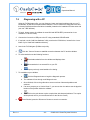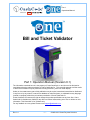
1
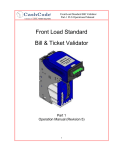
Part 1: Operational Manual A division of Bill and Ticket Validator Part 1: Operation Manual (Revision 8.1) The information contained here-in is the property of Crane CashCode co. and is not to be disclosed or used without the prior written permission of Crane CashCode Co. This copyright extends to all the media in which this information may be preserved including electronic, printout or visual display. Under no circumstances any part of this publication may be copied, transmitted, transcribed or distributed in any form or by any means, or stored in a database or retrieval system, or translated into any language (natural or computer) without the prior written permission of Crane CashCode Co. Crane CashCode Co reserves the right to change the product specifications at any time. Also, Crane CashCode Co disclaims any liability for any direct or indirect losses arising out of use or reliance on this information. This information is for guidance only. For any feedback or errors, please contact us at [email protected]. Rev. 8.1 -1- © 2009~2012 Crane Payment Solutions Part 1: Operational Manual A division of Table of Contents: 1. INTRODUCTION: 6 1.1. Glossary: 7 1.2. Safety Instructions: 8 1.3. Product Labels: 9 1.3.1. Validating Head 9 1.3.2. Housing 9 1.3.3. Cashbox 10 1.3.4. Additional Labels: 10 1.4. Product Documentation: 11 1.5. Product Overview: 12 1.5.1. Product Extensions: 12 1.6. Specifications: 14 1.6.1. Overall Specifications 14 1.6.2. Validator Specifications 16 1.6.3. Standard Cashbox Specifications 18 1.6.4. Expanded Cashbox Specifications 18 1.7. Compliance Approvals: 19 1.8. Standard Unit Dimensions: 20 1.8.1. Basic Configuration: 20 1.8.2. Alternate Configurations: 21 1.9. Expanded Unit Dimensions: 23 1.9.1. Basic configuration: 23 Rev. 8.1 -2- © 2009~2012 Crane Payment Solutions Part 1: Operational Manual A division of 2. MODULAR SYSTEM 24 2.1. Validating Head: 24 2.2. Housing: 25 2.3. Bezel: 26 2.4. Cashbox: 28 2.5. Accessories, OEM Harness & Training DVD Kit: 29 2.6. Memory Card: 32 2.6.1. Memory Card Part Number Legend: 32 2.6.2. Memory Card Options: 33 2.6.3. Memory Card Programming: 34 3. START UP AND INSTALLATION: 35 3.1. Start-up: 35 3.2. Installation of Main Unit: 35 3.2.1. Standard Housing: 36 3.2.2. Expanded Housing: 36 3.3. Upgrade Kit for Expanded Capacity 37 3.4. Security Switch Kit Installation: 38 3.5. Cashbox Lock Installation: 39 3.6. Interface connection: 40 3.6.1. Type 1 Interface Connection: 40 3.6.2. Terminal/Signal description for Type 1 Interface Connection: 41 3.6.3. Type 2 Interface Connection: 43 3.7. Input / Output Circuits: 44 3.8. Switch Settings: 45 Rev. 8.1 -3- © 2009~2012 Crane Payment Solutions Part 1: Operational Manual A division of 4. GDS CONFIGURATION: 47 4.1. Hardware Configuration: 47 4.2. PC Application Compatibility: 47 4.3. GDS Simulator Operation Guideline: 48 4.3.1. How to connect: 48 4.3.2. How to execute common commands & events: 49 4.4. GDS Firmware Features: 50 4.4.1. How to perform GDS Firmware Download: 50 4.4.2. How to verify GDS Bill Validator CRC: 51 4.5. GDS Failure Status: 51 5. MAINTENANCE AND SERVICE: 53 5.1. eLearning: 53 5.2. Collect Bills or Barcode Tickets: 54 5.2.1. Standard Cashbox: 54 5.2.2. Expanded Cashbox: 54 5.3. Preventative Maintenance: 55 6. SOFTWARE UPDATES: 56 6.1. Memory Card Update Procedure: 56 6.2. Download Procedure Via Interface Connector: 58 6.3. Download Procedure Via Front Service USB Port: 59 7. TROUBLESHOOTING: 61 7.1. Operation Mode Diagnostics: 62 7.2. Diagnosing with a PC 63 Rev. 8.1 -4- © 2009~2012 Crane Payment Solutions Part 1: Operational Manual A division of 8. CONTACT INFORMATION: 64 8.1. Technical Support Department: 64 8.2. Service Centers: 64 Rev. 8.1 -5- © 2009~2012 Crane Payment Solutions Part 1: Operational Manual A division of 1. Introduction: All CashCode products have two types of manuals: Part-1: Operation Manual Part-2: Service Manual This document is designed to help with the integration of the cashcode one™ bill Validator, both standard (600 / 900 / 1000) and expanded (2500) cashbox sizes. Use this manual for: Rev. 8.1 Unit dimensions and component nomenclatures, including mounting directions. Bill Validator specification and configurations, including hardware accessories. General specification for dip switch setting and software updates. Easy Diagnostic for any service requirements . -6- © 2009~2012 Crane Payment Solutions Part 1: Operational Manual A division of 1.1. Glossary: Anti Stringing Sensor – Sensor used to detect bills being pulled back illegally by using a string, wire or tape. Bar Code Sensor – Sensor to scan bar coded tickets BDP – Bi directional protocol Bezel – Face Plate BV – Bill Validator or Bill Acceptor Centering Mechanism – CashCode patented bill centering mechanism which aligns bills before entry into bill path CST – Cassette or Cash Box CPU – Central Processing Unit Dielectric Sensor – CashCode Patented Sensor used to measure the paper density DIP Switch – Dual Inline Package Switch Expanded Cashbox – 2500 Banknote Capacity cashbox GDS – Gaming Device Standard GSA – Gaming Standard Association one™/FLS – The CashCode one™ Frontload-Standard Bill Validator Memory Card – Portable programmable memory which can used to program BV without any tools Magnetic Sensor – Sensor used to read magnetic properties / ink on the bill Stacker Mechanism – A scissor type attachment used to stack the bill into cashbox TITO – Ticket In Ticket Out Standard U/V – Ultra Violet Sensor Rev. 8.1 - Caution / Safety Instructions - Comments / Notes -7- © 2009~2012 Crane Payment Solutions Part 1: Operational Manual A division of 1.2. Safety Instructions: Please follow the below guidelines: Please make sure the top lid is closed and the 24 pin connector is connected to the one™ Validator before power on. Please follow the specifications for operating temperature, humidity and storage conditions Do not lift or transport the unit by the cashbox handle. Be sure to remove power before removing the validating head. Please follow proper cleaning and maintenance procedures, ensuring the performance of the unit. Use care when carrying a fully loaded expanded cashbox, they may weigh up to 7 kg/15 lbs. All information about this product is available online, 24 hours a day. Visit our website at http://support.cashcode.com/ Rev. 8.1 -8- © 2009~2012 Crane Payment Solutions Part 1: Operational Manual A division of 1.3. Product Labels: 1.3.1. Validating Head FLSV-XXXX Validating Head Label one™ Bill Validator Label FLS/FLX Software Version Label Boot Version Label FLS-6XXX 1.3.2. Housing Main Product Label FLS-XXXX Main Product Label FLSH-000X Housing Label FLSH-000X Housing Label Rev. 8.1 -9- © 2009~2012 Crane Payment Solutions Part 1: Operational Manual A division of 1.3.3. Cashbox FLSC-0XXX Cashbox P/N Label FLSC-2500 Cashbox P/N Label 1.3.4. Additional Labels: Packaging Label (Box Exterior) Memory Card Label (See Section 2.6) Bezel Label (See Section 2.3) All Product Labels contain a generic part number and unique serial number. Rev. 8.1 - 10 - © 2009~2012 Crane Payment Solutions Part 1: Operational Manual A division of 1.4. Product Documentation: Document Type Document Part Numbers Descriptions User’s Guide: UG-FLS-XXXX_Rev XX Hardware Configuration. Software Release Specification: Software Users Guide: Standard: SRS FLS-_____-______ Rev XX Expanded Cashbox: SRS FLX-_____-______ Rev XX Dip Switch Settings, Bill Table Reference, Diagnostics, CRC Bill Set Descriptions: BSD-XXXX-X Picture of Accepted Bills and Denominations for specific software. Cashbox Users Guide: FLSC-XXXX Description and detail of Cash Box and its options. Bezel Users Guide: UG-FLSB-XXXX_X Details of Bezel, opening and mounting arrangement. Operational Manual: One_Part1_x Basic Operation Manual for CashCode One Bill Validator Service Manual: One_Part2_x Extended Manual with details on disassembling and servicing validator. OneTrack™ Operation Manual: Onetrack_Part1_x Basic Operation Manual and setup detail for OneTrack™ (RFID tag based soft counting) system. OneCheck™ Operation Manual Onecheck_Part1_x Basic Operation Manual and setup detail for OneCheck (TITO Printer based soft counting) system. CFS Downloader Manual Downloader_CFS_Manual_x Explains how to verify CRC and Update firmware through USB eLearning http://elearning.cashcode.com Interactive training for Operation and Service of your one™ Bill Validator, as well as OneCheck™ and OneTrack™ systems 3D Outline Model: Step or IGS format available upon request Contact your sales representative. You can also visit our website for available documents. http://support.cashcode.com/en/documentation/index.php Rev. 8.1 - 11 - © 2009~2012 Crane Payment Solutions Part 1: Operational Manual A division of 1.5. Product Overview: The one™ Bill Validator was developed to validate bills having a width up to 85 mm. Compared to the previous Front Load bill Validator models, the one™ has the following distinctive features: Utilizes a light-weight plastic shockproof cashbox and a plastic validating head. Universal platform allowing use of the device in both 12VDC and 24VDC applications utilizing different interfaces. The block of sensors contains ultra-violet sensor for improved counterfeit detection. Two barcode sensors allow 4-way acceptance of barcode tickets. The one™ BV consists of five main modules. Each module is available in different variations to suit your needs. The picture above illustrates the different modules: The one™ BV is designed to accommodate bills of different sizes from 62 to 85 mm wide, and from 125 to 172 mm long – which represents most of the world currencies. Certain currencies have different widths depending on denomination. For accurate validation of such currencies, the one™ Validating Head has a centering mechanism, which aligns the bills for processing of different widths. The lockable-removable Cashbox is used for temporary storage of validated bills. It can be locked with two standard ¾” tubular locks. Bill Capacity (600, 900, 1000 or 2,500 banknotes) refers to the number of new bills that the Cashbox can store. Actual Cashbox capacity can decrease in real applications due to variations in thickness of street-grade bills. The one™ Housing joins all the other modules. It is meant to be permanently secured inside a Gaming, Vending or other type of host machine. CashCode one™ is also available with GDS configuration, refer to related section. Several Bezel styles are available for the one™ BV. Software updates can be easily done with a Memory Card. 1.5.1. Product Extensions: The one™ product offers two optional systems that expand on the standard features to allow intelligent tracking and auditing of cashbox assets. The OneCheck™ system uses TITO coupons to track and store data. It is compatible with either Standard or Expanded cashbox sizes. The OneTrack™ system uses secure RFID electronic tracking in cashboxes. It is compatible only with Standard (600 or 1000) cashbox sizes. Please contact your sales representative for information on either system or sample requests. Documentation on the OneCheck™ and OneTrack™ system is available on http://support.cashcode.com Rev. 8.1 - 12 - © 2009~2012 Crane Payment Solutions Part 1: Operational Manual A division of One™ Validating Head Bezel Bezel Standard Housing Expanded Housing 600/900/1000 Bill Cashbox 2500 Bill Cashbox Memory Card Rev. 8.1 - 13 - One™ Validating Head © 2009~2012 Crane Payment Solutions Part 1: Operational Manual A division of 1.6. Specifications: 1.6.1. Overall Specifications Bezels and indication: No bezel installed. Green/Red Status Light. Standard: CashCode Style (Plastic or Metal), GPT Style, Cole Style, Konami Style, BAT Style Optional Bezel: Acceptance: Bills: Lengthwise 4 ways Accepted Denominations: Refer to Software Description Guide Validating Rate: 96% or higher (on first insertion) Supported Bill Width (mm): 62 - 85 Length of Bill supported(mm): 125 - 172 Bill Escrow: One Bill or One Barcode Ticket Bar Code Tickets: Bar Code Specification: Lengthwise 4 ways or 2 ways (refer to settings). Encoding standard: ANSI/AIM BC2-1995, Uniform Symbology Specification – Interleaved 2 of 5 Narrow bar width, in mm: 0.5 to 0.6 Wide/Narrow bar ratio: 3:1 Number of characters: 6 to 18 PCS (Print Contrast Signal) value: 0.6 min Bill processing cycle time: Standard Cashbox (600/900/1000 capacity): 3.2 seconds. 3.7 seconds. Expanded Cashbox (2500 capacity): Environmental Specifications: Allowed applications: Indoor only, outdoor for coated boards. Operating temperature: 0 C ~ +50 C Storage temperature: -20C ~ +60C Relative Operating Humidity: 30% - 90% (non-condensing) Relative Storage Humidity: 30% ~ 80% (non-condensing) Rev. 8.1 - 14 - © 2009~2012 Crane Payment Solutions Part 1: Operational Manual A division of Installation: Any in forward-back plane, vertical in left-right plane. Access to cashbox: From front side of the Validator. Outer Dimensions: (H x W x D) Standard Capacity (600/ 900 /1000): 300 mm x 115 mm x 235 mm (11.81 inch x 4.88 inch x 9.25 inch) Expanded Capacity (2500): 600 mm x 124 mm x 235 mm (23.62 inch x 4.52 inch x 9.25 inch) Unit Housing Weight: Standard Housing: 1.16 kg (2.56 lb) Expanded Housing: 1.58 kg (3.48 lb) Rev. 8.1 - 15 - © 2009~2012 Crane Payment Solutions Part 1: Operational Manual A division of 1.6.2. Validator Specifications Validation Sensors: 4-Color Reflective Optical Sensors: 3 Sets 1-Color Translucent Optical Sensors: 1 Set Dielectric Sensors: 1 (Differential) Inductive Sensors: 3 Anti Stringing Sensors: 1 Set Barcode Sensors: 2 (Upper cover and Lower Body) U/V Sensors: 1 Interface connector: 24-pin CC proprietary power and signal connector. Standard: USB on the back (excludes back mounting option); includes an extra board with USB data connector and a dedicated power connector (Molex 39-30-3045 or 39-30-3047). Optional: Supported Protocols and Interfaces: RS232 Secondary RS232 channel Opto-isolated serial (ID003) MDB Universal Platform: Cctalk CCS/VFM Optional: USB (additional board required), Netplex / SPC, GDS Service indication: Flashing of LED or the bezel lights. Service port: Front-service USB, Type B connector. Firmware Files CFS, BIN Memory programming: CashCode Memory card Interface controlled with NDEG card installed or using USB service port Supported memory stick types: CCFS format (Stay-in, One Time Programmable, or Multi-update) NDEG Rev. 8.1 - 16 - © 2009~2012 Crane Payment Solutions Part 1: Operational Manual A division of Mode selection: 12-position DIP switch Power supply voltage: 12 VDC ±5% or 24 VDC ±5% Current consumption: 12 V Standby: Operating Mode: Peak: 500 mA 2A 3A 24 V Standby: Operating Mode: Peak: 300 mA 1A 1.5 A Validating Head Outer Dimensions: (H x W x D) 96 mm x 115 mm x 234 mm (3.78 inch x 4.52 inch x 9.22 inch ) Validating Head Weight: 1.22 kg (2.69 lb) Rev. 8.1 - 17 - © 2009~2012 Crane Payment Solutions Part 1: Operational Manual A division of 1.6.3. Standard Cashbox Specifications Cashbox locks: Standard: No locks installed, only cams supplied. Shipped with shipping lock and cap. Optional: Special Cam for Australian OEM. Cashbox Free Fall Test: Functional Height: 1 meter. (Standard: IEC 68-2-32: 1975) Number of falls: 14 (6 sides, 6 edges, 2 corners) Maximum stacking capacity: (new bills) Up to 600 or 1000 banknotes Outer Dimensions: (H x W x D) 188 mm x 100 mm x 170.4 mm (7.40 inch x 3.94 inch x 6.71 inch) 600 Banknote Cashbox: 900 Banknote Cashbox: 188 mm x 100 mm x 207.4 mm (7.40 inch x 3.94 inch x 8.17 inch) 188 mm x 100 mm x 230.4 mm (7.40 inch x 3.94 inch x 9.07 inch) 1000 Banknote Cashbox: Unit Weight: 600 Banknote Cashbox (Empty): 1.1 Kg (2.42 lb) 900 Banknote Cashbox (Empty): 1.375 Kg (3.0314 lb) 1000 Banknote Cashbox (Empty): 1.4 Kg (3.08 lb) 1.6.4. Expanded Cashbox Specifications Cashbox locks: Standard: No locks installed, only cams supplied. Shipped with shipping lock and cap. Optional: Special Cam for Australian OEM. Cashbox Free Fall Test: Functional Height: 0.5 meters. (Standard: IEC 68-2-32: 1975) Number of falls: 14 (6 sides, 6 edges, 2 corners) Maximum stacking capacity: (new bills) Up to 2500 banknotes. Outer Dimensions: (H x W x D) 2500 Banknote Cashbox: 503 mm x 104 mm x 234 mm (19.8 inch x 4.09 inch x 9.21 inch ) Unit Weight: 2500 Banknote Cashbox (Empty): Rev. 8.1 3.52 kg (7.76 lb) - 18 - © 2009~2012 Crane Payment Solutions Part 1: Operational Manual A division of 1.7. Compliance Approvals: FCC class B CE Compliance U/L 756 RoHS Compliant CE Declaration is available upon request. Contact your sales representative for details. U/L listing can be found on http://www.ul.com/ Rev. 8.1 - 19 - © 2009~2012 Crane Payment Solutions Part 1: Operational Manual A division of 1.8. Standard Unit Dimensions: 1.8.1. Basic Configuration: one™ BV without Bezel, Foldable Handle Cashbox (600 Bills), Short Slide, No Switches: Side Mounting Points Rear Mounting Points All dimensions are in mm (inches in brackets) and are for reference only. Rev. 8.1 - 20 - © 2009~2012 Crane Payment Solutions Part 1: Operational Manual A division of 1.8.2. Alternate Configurations: one™ BV with 600 Flex Handle Cashbox: one™ BV with 900 Flex Handle Cashbox: one™ BV with 1000 Foldable Handle Cashbox: one™ BV with 1000 Flex Handle Cashbox: All dimensions are in mm (inches in brackets) and are for reference only. Rev. 8.1 - 21 - © 2009~2012 Crane Payment Solutions Part 1: Operational Manual A division of one™ BV with Long Slide: one™ BV with Security Switches: All dimensions are in mm (inches in brackets) and are for reference only. Rev. 8.1 - 22 - © 2009~2012 Crane Payment Solutions Part 1: Operational Manual A division of 1.9. Expanded Unit Dimensions: 1.9.1. Basic configuration: one™ BV without Bezel, Foldable Handle Cash Box (2500 Bills): Side Mounting Points Rear Mounting Points All dimensions are in mm (inches in brackets) and are for reference only. Rev. 8.1 - 23 - © 2009~2012 Crane Payment Solutions Part 1: Operational Manual A division of 2. Modular System A Modular System is an interchangeable group of parts – easily configured to a user’s specifications. Below is a table outlining configuration options: Base System Standard Capacity Validating Head Expanded Capacity Universal one™ Bill Validator Cashbox 600, 900 or 1000 Banknote Cashbox 2500 Banknote Cashbox Housing Standard Housing Expanded Housing Slide Short or Long Slide Slide not required Bezel Any, see section 2.3 for options Optional Components Product Extensions USB Interface, up to 2 Security Switches OneCheck™ or OneTrack™ OneCheck™ Contact your sales representative for sample request. Please note, GDS is not available with OneTrack™ feature. 2.1. Validating Head: The Validating Head with 24 pin output connector is universal and can be used in any indoor application. Validating Heads designed for outdoor use are available; please contact your sales representative. Rev. 8.1 - 24 - © 2009~2012 Crane Payment Solutions Part 1: Operational Manual A division of 2.2. Housing: The Housing is made of a rigid metal structure, which allows you to mount the validator using the left, right or back side. Standard Housing Expanded Housing IGT or GDS USB Housing Rev. 8.1 - 25 - © 2009~2012 Crane Payment Solutions Part 1: Operational Manual A division of 2.3. Bezel: The Bezels are U/L and CE compliant and 85 mm wide opening. Multiple bezel designs make the CashCode one™ Bill Validator compatible with a wide variety of door styles. Part Number Picture Description FLSB-5101 GPT Compatible Bezel with runway lights (Blue/Red) Cole Compatible Bezel with Runway Lights FLSB-530XY X-Variant: 1 – Full rectangle 3 – Flange cut top 5 – Raised bottom surface 7 – Flange cut top and raised bottom surface Flange Cut Top Y-Variant: Raised Bottom Surface _ - Green/Red Lights R – Red/Green Lights B – Blue/Red Lights FLSB-5401 Rev. 8.1 WMS BBXD Slant Top Bezel - 26 - © 2009~2012 Crane Payment Solutions Part 1: Operational Manual A division of CashCode Coin proof Plastic Bezel with optic channel for status light (Green/Red) FLSB-5501 Suitable for outdoor applications. Konami Compatible Bezel with open from top and runway light (Green/Red) X-Variant: FLSB-570X 1 – Standard 2 – AGT/Star games customized FLSB-5901 BAT (Aristocrat compatible) Bezel with oval shaped indicator light (Blue/Red) FLSB-5902 Verve Bezel (Aristocrat compatible) Bezel with oval shaped indicator light (Blue / Red) CashCode Coin proof Metal Bezel with optic channel for status light (Green/Red) FLSB-7103 This bezel requires additional grounding hardware on the unit housing. Please see the Bezel User Guide for mounting instructions. (Special Order) If you have custom bezel requirements, please contact your CashCode Sales Representative. Rev. 8.1 - 27 - © 2009~2012 Crane Payment Solutions Part 1: Operational Manual A division of 2.4. Cashbox: The Cashbox stores, stacks and holds validated bills in a secure cassette. The cashbox has a stacking mechanism and is typically equipped with a latch. Users are encouraged to replace the latch with a regular metal one. Users have a choice between one or two locks for added security. A locking mechanism allows for the installation of security locks (one or two 3/4” tubular locks measuring 11/16” ± 1/16” or 1 1/8” ±1/16”). All security locks are supplied by user. Although Cashboxes are available in 600, 1000, or 2500 bill storage capacity, street grade bills require more space and as a result full capacity may be reduced. The Cashbox can store bills from 60 to 85 mm wide and from 120 to 172 mm long. FLSC-0001* 600 Capacity, Foldable Handle FLSC-0002 600 Capacity, Flexible Handle FLSC-0101* 1000 Capacity Foldable Handle FLSC-0202 900 Capacity, Flexible Handle FLSC-2500** 2500 Capacity, Foldable Handle FLSC-0102 1000 Capacity, Flexible Handle *Special Order **Requires Expanded Housing Rev. 8.1 - 28 - © 2009~2012 Crane Payment Solutions Part 1: Operational Manual A division of 2.5. Accessories, OEM Harness & Training DVD Kit: If no special requirements have been indicated, then one™ will automatically be supplied with a 24-pin connector. Accessories P/N Description Remarks OPT-PS5-FLSDB9 Standard Power Supply. To be ordered separately. OPT-PS5-FLSDB9-01 OneCheck™-Enabled power supply. To be ordered with OneCheck™ system. OPT-MKFLSSWH Housing Kit with 1 Switch Option (Factory installed). To be ordered separately. If you need two switches, order qty – 2. OPT-MKFLSUSB Extra Kit for USB enabled device (Factory installed) To be ordered separately. OPT-MKFLSTRACK Upgrade/Replacement Kit for OneTrack™ expanded RFID functionality To be ordered with OneTrack™ system. OPT-MKFLS-SSTRACK Upgrade/Replacement Kit for OneTrack™ expanded RFID functionality To be ordered with OneTrack™ system. For use in upgrading units with old Short Slide installed. 5110086 Standard Lock Hasp Standard, supplied with every cashbox. 5110086-2 Special Lock Cam To be ordered separately. N/A Custom Harness (for each cabinet or application) Please contact your sales representative regarding appropriate harness option. P1848-FSM34 Blank Memory Card (Dallas Chip) See section 2.6 for description. To be ordered separately. P1848-FSM42 Blank Memory Card (CPU) See section 2.6 for description. To be ordered separately. Rev. 8.1 - 29 - © 2009~2012 Crane Payment Solutions Part 1: Operational Manual A division of List of custom OEM harness P/N Description FL85.00.011 Harness FLS-Spielo Onecheck FL85.00.012 Harness FLS Cole Onecheck FL85.00.013-01 Harness Assembly Aristocrat US MK-VI - Onecheck FL85.00.014 Harness FLS - OneCheck FL85.00.016-02 Harness Assembly Atronic Onecheck FL85.00.017-01 Harness Assembly K2 V Onecheck FL85.00.019-01 Harness Assembly Star Games Onecheck FL85.00.021-01 Harness Assembly Aristocrat Viridian Onecheck FL85.00.022 Harness FLS Aristocrat MKVI Excite FL85.00.023-01 Harness Assembly West Money Onecheck FL85.00.026-01 Harness Assembly VGT O/Check FL85.00.028-01 Harness Assembly Aruze Onecheck FL85.00.031-01 Harness Assembly Konami Podium O/Check FL85.00.033-01 Harness FLS Konami Adv 5 (O/Check) FL85.00.036-01 Harness Assembly Ainsworth A560 O/Check FL85.00.037-01 Harness Assembly Ainsworth Ambassador O/Check FL85.00.039 Harness Assembly - IGT FL85.00.040 FLS Harness Assembly (USB Ext) FL85.00.050-01 Harness Assembly WMS OneCheck FL85.00.055 GDS Harness Assembly FL85.00.055-01 GDS FLS Harness - OneCheck FL85.00.056 Onecheck Future Logic Gen-2 printer Harness FL85.00.057-01 Bally S6000 cabinet - OneCheck Rev. 8.1 - 30 - © 2009~2012 Crane Payment Solutions Part 1: Operational Manual A division of Training DVD & Product Demo Kit: Training Kit P/N Description Remarks OPT-FLS-CHECK-DEMO Onecheck demo kit with FL Gen2 Universal Printer in a carry case Please specify firmware OPT-FLS-TRACK- DEMO Onetrack demo kit with docking station in a carry case Please specify firmware. Also no thermal printer included. OPT-FLS-CHECK-SCAN Onecheck bar code scanner with stand Pls install applicable driver OPT-MKFLS-24 24 Pin Connector, Pins, Mounting Screws. Standard, supplied with every bill Validator. OPT-FLS-IT-DVD1 FLS Training Guide DVD Elearning for public OPT-FLS-IT-DVD2 FLS Training Guide DVD Elearning for Casino operator and OEM OPT-FLS-IT-DVD3 FLS Training Guide DVD Elearning suite for Service Centers and advanced users OPT-FLS-IT-DVD4 FLS Video only DVD (iPod) VIDEO ONLY FOR IPHONE -FLS Introduction, Level 1, 2, 3 Maintenance, Paycheck, Video-Only (indexed) OPT-FLS-IT-DVD5 FLS Video only DVD VIDEO ONLY -FLS Introduction, Level 1, 2, 3 Maintenance, Onecheck OPT-FLS-IT-DVD6 FLS Video only DVD VIDEO ONLY FOR BLACKBERRY FLS Introduction, Level 1, 2, 3 Maintenance, Paycheck, Video-Only OPT-FLS-IT-GDS DVD with GDS Simulator DVD with GDS Simulator for FLS OPT-FLS-IT-MAN-DVD FLS Documentations DVD FLC documentation including operational manual, spare part list, flip book, flyer, onecheck manual OPT-FLS-IT-PC3 One PC Applications - Service DVD for Customer (ONE navigator, Intdesk, ccnet stat, drivers and card maker) OPT-FLS-IT-PC4 OneCheck Software DVD Customer OneCheck DVD with BarCode Scanner Software, IIS Files, Manual and Drivers for Customer OPT-FLS-IT-PC5 OneCheck Software DVD Prod. OneCheck DVD w BarCode Scanner Software, IIS Files, Manual and Drivers for Production Rev. 8.1 - 31 - © 2009~2012 Crane Payment Solutions Part 1: Operational Manual A division of 2.6. Memory Card: Each CashCode one™ Bill Validator is supplied with pre-installed software or a Stay-In Memory Card (for gaming applications), according to users order. A Stay-In Memory Card may be a single download, a one time programmable, or an NDEG card. Software updates are recommended whenever: New currency is issued, or A new series of counterfeit bills are discovered. 2.6.1. Memory Card Part Number Legend: F_M-34US20-361011 Type 31 Memory Card: FSM – Standard one™ BV Memory Card FXM – Expanded Capacity BV Memory Card 34 – Type of memory card (see table) US – Country code (ISO 3166-3) 20 – Protocol/OEM Customization Dallas Chip, 128 K Memory Type 34 Memory Card: Dallas Chip, 512 K Memory Software version: 36 – Control Firmware 10 – Validation Firmware 11 – C/C Code Configuration Type 42 Memory Card CPU Chip, 512 K Memory Memory Card Type Mfg. Download Single Download* One Time Programmable* Kobetron Signature Verification MultiDownload NDEG Service USB Enabler 31 X X X X X √ X 34 √ √ √ √ X √ √ 42 √ √ √ X √ √ √ * OTP and Single Download Card do not allow Service USB firmware download function. For this purpose you must first insert USB enabled Memory card, followed by specific country firmware. All firmware version FLS-xx44-xxxxxx onward supports front USB flash update. Rev. 8.1 - 32 - © 2009~2012 Crane Payment Solutions Part 1: Operational Manual A division of 2.6.2. Memory Card Options: Single Download (Stay-In) Memory Card: Example Part Number: FSM-34US20-080500 New software can be ordered on single-download Memory Cards. The software from the new Memory Card is downloaded as soon as it is inserted into the slot, and the Validating Head is powered on. The Memory Card must be present at all times for the Bill Validator to operate. The Stay-In/Single Download update scheme is the recommended option for gaming applications. One Time Programmable (Stay-In) Memory Card: Example Part Number: FSM-34US20-080500-OP The One Time Programmable (OTP) Card is a Single-Update/Stay-In type memory card that has been locked as read-only. When a one™ Bill Validator is updated using an OTP card, it is locked to only accept software updates through OTP cards in the future. This is applicable to NJ Jurisdiction only. NDEG (Stay-In) Memory Card: Example Part Number: FSM-34C02 A special Memory Card can be ordered, which allows the download of new software through the interface connector. After the download, the Memory Card must be present in the Validating Head at all times. If the host controller supports the CCNET interface, then the download can be done via the host controller (and local network). Other interfaces do not support this download feature. Downloads in this case can be completed with any personal computer (PC or laptop) and a CashCode adapter. (The Validator must be temporarily disconnected from the host controller). Multiple Download Card: Example Part Number: FSM-34US20-080500-XX New software can be ordered with a multi-download Memory Card. The multi-download Memory Card can be used for updating multiple one™ Bill Validator, depending on the number of licenses ordered. Subsequently, the card does not have to remain inside the unit during operation. Typically a multi-download Memory Card is issued for a limited number of downloads (maximum 99), and therefore the number of licenses required must be defined in the user’s order. USB Enabler Memory Card: Example Part Number: FSM-34US20-080500-UB A USB Enabler memory enables future software updates through the front service USB port of the one™ Validator. This option can be attached to any of the above memory card options. Unless otherwise specified, all one™ Bill Validators manufactured after April 2010 are USB enabled by default. Procedures for software updates can be found in section 5. Rev. 8.1 - 33 - © 2009~2012 Crane Payment Solutions Part 1: Operational Manual A division of 2.6.3. Memory Card Programming: There are several tools available to program memory cards with the appropriate software. Software upgrades are ordered through the CashCode customer service department. P1848 Single-Card Programmer P3418 Multi-Card Programmer (Mobile) For information, operational instructions and availability please contact your Crane Payment Solutions sales representative. Rev. 8.1 - 34 - © 2009~2012 Crane Payment Solutions Part 1: Operational Manual A division of 3. Start Up and Installation: 3.1. Start-up: To avoid damage of any kind during start-up process, please carefully check all points specified below: Make sure to use proper cable harness based on interface and cabinet. Power supply must conform to the specification on the label. Proceed as follows to install the one™ Bill Validator in the main cabinet. 3.2. Installation of Main Unit: The one™ Bill Validator is installed by using (3) M4 screws on each side of the Front Load frame. The length of these screws should not be longer than required. Otherwise they may protrude through the inside of the frame. If the position of the mounting screws is different than the position of the mounting holes provided in the target equipment, then additional frame mounting components may be required. The BV can also be secured through the holes in the rear wall of the Housing. In this case, M3 screws and locator pins can be used. For dimensions of the mounting holes, please refer to the dimensional drawings (Section 1.6). Please note that although the mounting on both configurations is identical and may be swapped out, the expanded housing is approximately 11 mm wider than the Standard Housing and may require more space if mounted from the back. To order separate component for your installation, see below the list: P/N Description OPT-MKFLS-HS 2 spare screws and 2 space lock washers to mount the interface harness 8202A13 Nut to secure the chassis ground wire 8203067 Washer to secure the chassis ground wire For bezel installation, following spare parts may be required: P/N Description 8201000 2 spare screws to mount the bezel (Screw, M3x6, PH, ZI) 8203927 2 spare washers to secure the bezel (Flat washer, M3, ZI) Please see the appropriate User Guide for your Bezel to ensure proper grounding. Rev. 8.1 - 35 - © 2009~2012 Crane Payment Solutions Part 1: Operational Manual A division of 3.2.1. Standard Housing: Two Holes O 3.5 Two Holes O 4.0 Four screws M4 Two Holes O 4.0 Two locator pins Four screws M4 See Section 1.8.1 for mounting dimensions. 3.2.2. Expanded Housing: Three screws M4 76 101.6 Four holes 4.2x4.6 Four screws M4 See Section 1.8.2 for mounting dimensions. Rev. 8.1 - 36 - © 2009~2012 Crane Payment Solutions Part 1: Operational Manual A division of 3.3. Upgrade Kit for Expanded Capacity To upgrade from standard to expanded cashbox sizes, you must use the appropriate upgrade kit (OPT-MK2500-KIT_). This kit will replace your existing housing, cashbox, and validator software to operate with the larger (2500 note) cashbox size. To perform the conversion: 1. Remove the Validating Head (and cashbox) from the standard housing. 2. Unmount the standard housing from the host machine, if required. 3. Mount the expanded housing in the host machine (see section 3.2). 4. Update the one™ BV software to operate with the expanded cashbox size using either a memory card or direct update procedure, as specified by the upgrade kit (see section 6). 5. Insert the expanded Cashbox into the expanded Housing. Please note that although the mounting on both configurations is identical and may be swapped out, the expanded housing is approximately 11 mm wider than the Standard Housing and may require more space if the unit is rear-mounted. Rev. 8.1 - 37 - © 2009~2012 Crane Payment Solutions Part 1: Operational Manual A division of 3.4. Security Switch Kit Installation: The optional security switch kit (Part Number: OPT-MKFLS-SWH) allows the host machine to detect whether a cashbox is present in the validator Housing. Security switches can be installed on one or both sides of the housing, and need to be ordered together with your one™ bill validator for factory installation. Skip to step 3 unless you are installing the switch inside the housing yourself: 1. Attach the provided cable to the security switch as shown in the diagram. 2. Use a #2x1/2” wood screw to secure the switch to the bill validator Housing. 3. Install the housing inside the host machine as shown in section 3.2. 4. Feed the cable up through the housing and connect the applicable wires in the appropriate port of your host machine: Brown Wire – NC (Normally Closed) Switch: This contact is opened when a cashbox is inside the housing. Red Wire – NO (Normally Open) Switch: This contact is closed when a cashbox is inside the housing. Orange Wire – Common Ground. NO NC Ground Rev. 8.1 - 38 - © 2009~2012 Crane Payment Solutions Part 1: Operational Manual A division of 3.5. Cashbox Lock Installation: In order to install the security locks into the Cashbox, open the Cashbox cover, remove the plastic lock and plug, and follow the diagram shown below: The cashbox design supports 1 to 2 locks, either 5/8” or 1 1/8” in length. Suitable manufacturers include MEDECO, KABA, ABLOY, VSR, and Bilock. Hex Nut Washer Hasp (5110086) Nut Cassette Washer Lock Cover 9 max Two standard locking hasps are shipped with every cashbox: P/N - 5110086 Standard Square head locks are special order and must be specified when ordering: Ø19.05 [3/4"] 15.88 [5/8"] The locks must rotate in opposite directions (one lock 90 degrees clockwise and second should be 90 degrees counterclockwise - see figure on the left). A P/N - 5110086-02 Square head Ø22.2max Ø7.14 [9/32"] 3.03 max 5.56 [7/32"] 5 A= 8" or A=118" Due to variations in regulatory requirements, Crane Payment Solutions does not provide locks, but we provide cam and applicable washers. Detailed Dimension of Slot for Lock Rev. 8.1 - 39 - © 2009~2012 Crane Payment Solutions Part 1: Operational Manual A division of 3.6. Interface connection: The one™ Bill Validator has the flexibility of five different protocol/interface options: Type 1: RS232 levels (CCNET), Opto-Isolated (BDP), V2.2, Isolated Pulse Low Current or RS485, 24 pin validating head. Type 2: USB, 24 pin validating head. 3.6.1. Type 1 Interface Connection: For the type 1 connection, the Host Controller may reset Bill Validator by holding line M-RES “active” for 1 ms. this informs the Bill Validator to abort any activity and return to its power-on reset state. Rear Connector Pin Assignment: 1 6 7 13 12 18 19 24 Plug Housing P/N: #5105068 (View from the back of Bill Validator) Mating Socket P/N: #0100455 (CashCode 24 Pin Connector), Contact Crimp Terminal: DR-SC24-1-7000 (JAE) For detailed interface descriptions, please refer to the corresponding Interface (Protocol) Description Manual. The manuals may be downloaded from the CashCode website at http://support.cashcode.com/en/documentation/index.php Rev. 8.1 - 40 - © 2009~2012 Crane Payment Solutions Part 1: Operational Manual A division of 3.6.2. Terminal/Signal description for Type 1 Interface Connection: TERMINAL SIGNAL FUNCTION ACTIVITY 1* GROUND GROUND BUS - 2 RxD-EXT RECEIVE DATA HIGH/LOW 3 TxD-EXT TRANSMIT DATA HIGH/LOW 4 VCC POWER - 5 GND GROUND - 6 RXD-EXT1 RECEIVE DATA HIGH/LOW - 7** GND-EXT/EXT1 INTERFACE GROUND - 8 TXD-EXT1 TRANSMIT DATA HIGH/LOW - 9 RS485-A RS485 BUS - 10 RS485-B RS485 BUS - 11 INP-RXD INPUT SIGNAL/ RECEIVE DATA - 12 INP-TTL1 INPUT SIGNAL - 13** POWER- POWER 0V - 14 INP-TTL2 INPUT SIGNAL - 15 OC-TXD OUTPUT SIGNAL (OPEN-COLLECTOR )/ TRANSMIT DATA - 16 OC-OUT1 OUTPUT SIGNAL (OPEN-COLLECTOR ) - 17 C-LED-BDP / OC-OUT2 LED CATHODE/ OUTPUT SIGNAL (OPENCOLLECTOR ) - 18 A-LED-BDP LED ANODE - 19 POWER+ POWER 12V/24V - 20 TXD-BDP TRANSMIT DATA HIGH/LOW 21 RXD-BDP RECEIVE DATA HIGH/LOW 22 RST-BDP MASTER RESET LOW 23 GND-BDP INTERFACE GND - 24 +12V BDP INTERFACE POWER - Rev. 8.1 - 41 - © 2009~2012 Crane Payment Solutions Part 1: Operational Manual A division of The channel identified by EXT (pins 2, 3 and 7) is assigned for RS232 level interface (CCNET). A second RS232 level channel identified by EXT1 (pins 6 and 8) is currently reserved. The channel identified by BDP (pins 20 to 24) is assigned for Opto-Isolated interface (BDP). Recommendations: Chassis Grounding Functional Grounding *Please connect Terminal 1 (Functional Grounding) to validator housing in order to eliminate external interference (i.e.: inside rear of housing): **Do not connect Terminal 7 and 13 on the same connector. Rev. 8.1 - 42 - © 2009~2012 Crane Payment Solutions Part 1: Operational Manual A division of 3.6.3. Type 2 Interface Connection: Rear USB Pin Assignment: USB “B” Plug TERMINAL SIGNAL FUNCTION ACTIVITY 1 +5 V POWER - 2 D- USB BUS, DATA- - 3 D+ USB BUS, DATA+ - 4 GND POWER - Power Pin Assignment: Socket 39-01-4040 (MOLEX) TERMINAL SIGNAL FUNCTION ACTIVITY 1 +12V DC POWER - 2 GND POWER - 3 GND POWER - 4 +24V DC POWER - Rev. 8.1 - 43 - © 2009~2012 Crane Payment Solutions Part 1: Operational Manual A division of 3.7. Rev. 8.1 Input / Output Circuits: RS 232 RS 485 CCTALK OPTO ISOLATED ID003 CCS / VFM: - 44 - © 2009~2012 Crane Payment Solutions Part 1: Operational Manual A division of 3.8. Switch Settings: The switches are located on the side of the Validating head near the bottom. The first series of four (4) DIP switches is defined below. Only the switch 2.4 should be used during operation and diagnostic of the one™ Bill Validator, to switch between: Host Mode: This is the normal operational mode for the validator Service Mode: This mode is only for testing the Validator and does not require the connection to a host machine. ON State of switch 1 2 3 4 OFF State of switch Parameter Switch On Off Orientation of the ticket SW2.1 Bar Code - Four-Way Bar Code – Face Up Stacker orientation SW2.2 Down Up Product Extension setting SW2.3 OneCheck™ OneTrack™ Mode SW2.4 Service Mode Host Mode Rev. 8.1 - 45 - © 2009~2012 Crane Payment Solutions Part 1: Operational Manual A division of Switch 2.3 configures which one™ product extension is expected by the validator. If no machine or location number is assigned to the validator, it will operate in OneCheck™ mode by default. For details on the OneCheck™ or OneTrack™ system, please see the appropriate operation manual at http://support.cashcode.com/en/documentation/index.php. The second series of eight (8) DIP switches control accepted denominations and acceptance settings. ON State of switch 1 2 3 4 5 6 7 8 OFF State of switch Parameter Switch On Off Denomination #1-7 SW1.1-7 Enabled Disabled Acceptance Mode SW1.8 Accept All Reject Unfit Bills For Switch 1.8, both settings use the same security algorithms. On setting attempts to accept all legitimate bills even if there is some damage to them. Off setting rejects legitimate but damaged bills. Examples are bills that have been glued or have large holes or pieces missing. DIP switch setting may vary based on software requirement for specific country or customer. For a complete explanation of switch settings, please refer to “software version description” for your particular Bill Validator. You can find at http://support.cashcode.com/en/documentation/index.php . Rev. 8.1 - 46 - © 2009~2012 Crane Payment Solutions Part 1: Operational Manual A division of 4. GDS Configuration: 4.1. Hardware Configuration: Our GDS products are USB 2.0 compliant and support Full Speed (12 Mbits/sec). Complete Unit Part Number: P/N Description Main Unit FLS-5021 Housing Assembly, Validating Head, 600 Flex handle cash box, GDS OneCheck compatible cable, USB cable Main Unit FLS-5022 Housing Assembly, Validating Head, 1000 Flex handle cash box, GDS OneCheck compatible cable, USB cable Accessories Part Number: P/N Description FL85.00.029 GDS Power Cable OPT-PS5-FLS-USB USB Power Supply FL85.00.055 GDS Communication cable FL85.00.055-01 GDS Communication cable with Onecheck All Standard available bezel and cash box are fully compatible with above unit. 4.2. PC Application Compatibility: Following applications are supported by our GDS compatible bill validator product: Rev. 8.1 GDS Simulator (available at GSA website www.gamingstandards.com ) - 47 - © 2009~2012 Crane Payment Solutions Part 1: Operational Manual A division of DFU Driver (available at http://www.usb.org/developers/devclass_docs/DFU_1.1.pdf ) For installation, follow their guideline or contact our tech support. For all protocol documents for Note Acceptor refer to their website www.gamingstandards.com (Document Name: GDS_NA_xx.pdf) & DFU class available on USB http://www.usb.org/developers/devclass_docs/DFU_1.1.pdf CashCode PC applications supported by GDS Bill Validator: 4.3. Navigator CFS Downloader CCNet Stats CRC Verifier GDS Simulator Operation Guideline: 4.3.1. How to connect: It is required to have GDS tool kit (USB Diagnostic V1.1) installed on your window based computer. Connect USB cable to your computer, USB power supply and USB cable to back of Bill Validator. You will hear the stacker motor cycling sound , bezel light will remain RED Quick trouble shoot tips: On some window application, device may not be detected right away. It is recommended to connect to Bill Validator in less than 10 secs, once connect the power Upon completion of BV cycle (stacker motor sound), launch USB Diagnostic Suite. Select Device Diagnostics, then Note Acceptor, as shown here then Note Acceptor window will pop up Rev. 8.1 - 48 - © 2009~2012 Crane Payment Solutions Part 1: Operational Manual A division of 4.3.2. How to execute common commands & events: We support all commands explained as per GDS protocol table 3.1. We also support all events specified as per GDS protocol table 4.1. Please find below few examples using GDS simulator. Before you start your operation, we prefer you to select “Auto Refresh” to view communication log. Quick trouble shoot tips: To enable bill validator, first you must “DISABLE” bill validator, then “ENABLE” it. Bezel light will be turn into Green or Blue (depends on bezel). This means now device ready for accepting the money or barcode coupon. READ TABLE: Make sure BV is disabled, now you are ready to view denomination type and barcode supported by existing firmware, click first on Note Entry, and then on Read Table Quick trouble shoot tips: To view communication log, click on tab “Inbound/Outbound Note Acceptor Device Traffic” NOTE / BARCODE TICKET ACCEPTANCE: Make sure BV is enabled. Rev. 8.1 Insert the note and in less than 5 seconds you need to click Accept Note, this will stack it into the cash box. In the field Note/Ticket Validated, you will be able to see the Type of Note ID or Barcode Ticket Number. If you want to reject the note or Barcode, then after insertion you can click Return Note. If you want to hold the note or coupon in Escrow you can click every 10 seconds or so Extend Timeout, this will allow you to hold the note in escrow position. - 49 - © 2009~2012 Crane Payment Solutions Part 1: Operational Manual A division of 4.4. GDS Firmware Features: CashCode One firmware is developed based on GDS protocol released by GSA and DFU class. Our firmware file is available in “.bin” format. 4.4.1. How to perform GDS Firmware Download: If you are planning to update through Method-1 & 2, please make sure that unit does not have any stay in memory card or one time programmable memory card. METHOD-1: GDS Simulator - DFU Run USB Diagnostic Suite, as explained in above section. Click on DFU Icon as shown here. New Window will pop up. Quick trouble shoot tips: Based on various window operating system, we recommend you to click first on DETACH button (inside Device Firmware Upgrade DFU window). Then close and restart USB Diagnostic Suite application again. Once, you reopen the DFU window, please follow below steps: Press DOWNLOAD button from DFU window. Select applicable Bill Validator firmware files (.bin) & Click OPEN. Firmware update will start. (Please ignore Non DFU extension message). You will see progress bar on your screen as it is updated 100%. METHOD-2: CFS Downloader, refer to CFS Downloader Manual METHOD-3: Memory card, refer to related section. Rev. 8.1 - 50 - © 2009~2012 Crane Payment Solutions Part 1: Operational Manual A division of 4.4.2. How to verify GDS Bill Validator CRC: GDS supports CRC 32. To verfiy CRC, make sure BV is disabled. Change the seed values to 0x00000000, then click on button Get CRC. CRC will be displayed on your screen. Alternatively, CRC can also be verified by CashCode CRC Verifier or CFS Downloader PC application. Make sure to setup seed 0. Connect PC to USB frontal port of Bill Validator, run the application CRC Verifier and select type of CRC, finally just select Get CRC. For more detail refer to Downloader_CFS_Manual. 4.5. GDS Failure Status: CashCode One is capable of supporting network diagnostics or failure status as indicated in GDS Note Acceptor Protocol Document table 4.14 and 4.15. ON SITE INDICATOR: If an error occurs, it will begin to flash red or green. Count the flashes and use the table to diagnose any problems with your CashCode One™ validator. NETWORK DIAGNOSTICS: CashCode One is capable of supporting network diagnostics or failure status as indicated in GDS Note Acceptor Protocol Document table 4.14 and 4.15. Please contact our tech support, if any further questions. SELF TEST: You can perform network diagnostics using GDS simulator. Once device is connected, see below an example how to get failure status. Rev. 8.1 - 51 - © 2009~2012 Crane Payment Solutions Part 1: Operational Manual A division of Click on Note Acceptor. Press Disable. Now we ready for self test, press Self Test tab, Above window will indicate type of failures specitied in GDS protocol table 4.15 Rev. 8.1 - 52 - © 2009~2012 Crane Payment Solutions Part 1: Operational Manual A division of 5. Maintenance and Service: 5.1. eLearning: Crane Payment Solutions offers interactive online and video training for installation, maintenance, update, and service procedures for the one™ Bill Validator. Please see http://elearning.cashcode.com/ for up-to-date training videos and instructions. Some content will require you to create an account with CashCode support. Please register at http://support.cashcode.com/, or contact [email protected] for quick and easy access today! Rev. 8.1 - 53 - © 2009~2012 Crane Payment Solutions Part 1: Operational Manual A division of 5.2. Collect Bills or Barcode Tickets: To collect bills from the one™ Bill Validator, simply pull out the Cashbox using the handle. To open the Cashbox cover, open the locks located at the two corners. To replace the Cashbox, close the cover and insert the Cashbox into the one™ housing. 5.2.1. Standard Cashbox: 5.2.2. Expanded Cashbox: Rev. 8.1 - 54 - © 2009~2012 Crane Payment Solutions Part 1: Operational Manual A division of 5.3. Preventative Maintenance: During normal operation, dust and dirt accumulate on the optical sensors and the rollers of the validating head and cashbox, possibly resulting in a reduced acceptance rate. The bill path should be cleaned every 6 months or after acceptance of 60,000 bills, whichever comes first. Please follow the instructions below. Transport Rollers Lenses O-Rings Procedure: 1. Open the top cover of the validating head. 2. Use compressed air to blow away all loose particles from the bill path and cashbox chamber. 3. Wipe away any remaining dirt with a soft, moist cloth. 4. Check all lenses for scratches and clean with a soft cloth and clean water. 5. Check for cracked o-rings and transport rollers and clean them using a soft cloth with isopropyl alcohol (70%). 6. If any lenses, o-rings, or rollers are damaged, contact your closest service centre to have them replaced. 7. (Not Pictured) Use compressed air to blow all loose particles out of the cashbox vault. Use a soft, moist cloth to clean the orings on the cashbox bill path. DO NOT use Acetone, Petroleum, or Mineral oil based cleaning products as they will cause damage to validator parts and void your warranty. For interactive training on maintaining your one™ Bill Validator, please see the http://elearning.cashcode.com website. Rev. 8.1 - 55 - © 2009~2012 Crane Payment Solutions Part 1: Operational Manual A division of 6. Software Updates: The one™ Bill Validator is shipped with pre-installed software or as a vanilla unit, according to a user’s ordered specifications. It is recommended to keep your BV up to date. You can order updates from CashCode as they become available using the original part number for your system. Please verify your jurisdictional requirements for pre-installed or update software before following these directions. 6.1. Memory Card Update Procedure: 1. Turn Power OFF. 2. Lift up the Latch under the Validating Head, and Remove the Validating Head from the Housing. Rev. 8.1 - 56 - © 2009~2012 Crane Payment Solutions Part 1: Operational Manual A division of 3. Insert the new CashCode Memory Card into the Memory Card slot of the Validating Head (for correct insertion, please see diagram below). Memory Stick Label should face down and notch on memory stick should face the left as per diagram above. 4. Insert the Validating Head into the Housing. 5. Turn Power ON and wait until the download process is completed. During the download, a redgreen status light will blink. 6. After the download, if the validator is in Host Mode, the status light will turn steady red. If the validator is in Service Mode, the validator will automatically initialize. If the status light presents steady-red with green flashes after the update procedure, please see the next section (9 Software update diagnostics). 7. After the update, a single-download Memory Card must be present in the Bill Validator at all times during operation. A multiple-download card can be removed and used to update more units, until the number of licenses is reached. Rev. 8.1 - 57 - © 2009~2012 Crane Payment Solutions Part 1: Operational Manual A division of 6.2. Download Procedure Via Interface Connector: In order to properly complete an interface download, the Network Download Enable Memory Card must be present in the Memory Card slot at all times – before, during and after the download. For a direct download in the service mode via the interface connector, please follow the instructions below: 1. Turn power OFF. 2. Disconnect the interface connector from the Bill Validator. 3. Remove the Validating Head from the Housing, and set Mode Switch to Service mode (Refer to section 3.7). 4. Install the Validating Head into the Housing. 5. Connect the CashCode Adaptor: a) to the Computer, b) to the interface connector of the Bill Validator, and c) to the power outlet (AC 100-250V). 6. From the computer, run the latest software version of the program. 7. Follow the instructions displayed on the computer screen. 8. After completing step 7, disconnect the CashCode Adaptor: a) from the power outlet, b) from the Bill Validator, and c) from the Computer. 9. Remove the Validating Head from the Housing, and set Mode Switch to Validation mode (refer to section 3.7). 10. Install the Validating Head into the Housing. 11. Connect the interface connector to the Bill Validator. When the one™ Bill Validator has a CCNET protocol, the software download can be completed via the host controller (refer to CCNET Protocol Description). Rev. 8.1 - 58 - © 2009~2012 Crane Payment Solutions Part 1: Operational Manual A division of 6.3. Download Procedure Via Front Service USB Port: In order to perform a software update through the front service USB port, the one™ Bill Validator must be USB-enabled using a USB enabling (–UB) memory card. The PC used for the installation must also have the latest CashCode software and drivers installed (located on the installation CD that came with your one™ Bill Validator) 1. To begin, please ensure the validator is turned ON and connected to a host machine. 2. Connect the Validator’s front service USB port to the PC using a standard USB A/B cable. 3. If required, use the “Add New Hardware” utility to select the VCOM driver, located in the /vcom/ folder of your CashCode installation directory. 4. Launch the USB firmware update utility (DownloadCFSFile.exe) utility. 5. Select “Load” and pick your software update file. 6. Select “Start”. 7. The firmware update process will be accompanied by a rapidly blinking red/green status light for approximately a minute. Please wait until the update is finished before proceeding. 8. Remove the USB Connection. 9. After the download, if the validator is in Host Mode it will require a RESET command from the host to complete the update procedure. If the validator is in Service Mode, the validator will automatically initialize. If the status light presents steady-red with green flashes after the update procedure, please see the next section (9 Software update diagnostics). Rev. 8.1 - 59 - © 2009~2012 Crane Payment Solutions Part 1: Operational Manual A division of Software Update Diagnostics: Normally, the download process will be accompanied by a blinking red-green status light for about 1 minute. If the download has competed successfully, the status light will turn green. Should the download be unsuccessful, the status light will turn red, with short green flashes. The following table lists possible errors which may take place during a download: Green Flashes 1 2 Error Solution Unable to write program memory Firmware integrity error Turn POWER OFF, remove and insert the Memory Card again, turn POWER ON. Send validating head for service Reprogram device using proper Memory Card Follow the next steps checking whether device went back to operation: Verify that the software is suitable to the Bill Validator type. 3 Wrong memory card Insert correct type of CashCode Memory Card. Turn POWER OFF, remove and insert the Memory Card again, turn POWER ON. Replace Memory Card with the new one. 4 Rev. 8.1 Verify that software is suitable for download. Security error Repeat procedure. - 60 - © 2009~2012 Crane Payment Solutions Part 1: Operational Manual A division of 7. Troubleshooting: CashCode’s one™ Bill Validator is equipped with a self-diagnostic feature to aid in repair and maintenance. When the power to the Bill Validator is turned ON, the Bill Validator begins its selfdiagnostic operation. If the self-diagnostic test is passed, then the status light will turn green. If an error is detected, then the status light on the front of the Bill Validator will blink red. The number of times the red light flashes on the Bill Validator is an indication of a specific problem or malfunction. A detailed list of these errors and corrective action is provided in the Diagnostics section to follow. Status Indicator Rev. 8.1 - 61 - © 2009~2012 Crane Payment Solutions Part 1: Operational Manual A division of 7.1. Operation Mode Diagnostics: During normal operation, the status light remains a steady green. If an error occurs, it will begin to flash red. Count the flashes and use the following table to diagnose any problems with your one™ validator. Red Flashes Error Solution 1 Cashbox is removed from bill Validator Check if Cashbox is installed correctly 2 An error occurred during CPU exchange with magnetic board Reset device power; if the problem persists, send device for repair. 3 Cashbox is full Remove Cashbox, empty Cashbox and insert empty Cashbox. 4 Mechanical Jam in Cashbox or Stacker fail Remove Cashbox from Bill Validator Housing and extract crumpled or jammed bill. 5 Failure of die-electric Sensor Reset device power. 6 Failure of Optical Sensor Open Validator head guide, clean optical sensors (please see section 5.3 for cleaning details on these sensors). 7 Failure of Magnetic Sensor Open Validator head guide, clean inductive sensors (please see section 5.3 for cleaning details on these sensors). 1. Open Validator head guide, clean path. 2. Close Validator head guide. 8 Failure of Transport Motor 3. If Validator does not start, turn off power, release Validator head and check receiving path. 4. Insert Validator head and turn power on. 9 Speed of Transport motor is too fast Check power supply voltage. 10 Failure in alignment mechanism See Solution 8. 11 Bill pathway is not empty 12 Bill jam in entry slot and no credit is issued Open receiving path and check that it is clean. 13 Overload of transport motor Open Validator head guide and check to see if path is clean. 14 System Error Reset device power. 1. Open receiving path and check that it is clean. 2. Remove Cashbox from bill Validator and clean path. If any problems persist, contact your nearest service center or CashCode Technical Support. Rev. 8.1 - 62 - © 2009~2012 Crane Payment Solutions Part 1: Operational Manual A division of 7.2. Diagnosing with a PC Using the FLS Navigator utility, you can diagnose, locate, and repair problems with your one™ bill validator, as well as check performance statistics. The PC used for the diagnostic must have the latest CashCode software and drivers installed (located on the installation CD that came with your one™ Bill Validator). 1. To begin, please ensure the validator is turned ON and INITIALIZED (connected to a host machine or in service mode). 2. Connect the front service USB port to the PC using a standard USB A/B cable. 3. If required, use the “Add New Hardware” utility to select the VCOM driver, located in the /vcom/ folder of your CashCode installation directory. 4. Launch the FLS Navigator (FLSNav.exe) utility. 5. Click the “Connect” button to establish connection between the PC and the validator. 6. To collect statistics use the following functions: a. Downloads statistics from the validator and displays them. b. Saves statistics in an external file on your PC. c. Opens previously saved statistics for viewing. 7. To troubleshoot your validator: a. Click the Diagnose button to begin the diagnostic process. b. The validator will run through a self-diagnostic test. c. Once finished, click on the guide tab to see an overview of detected problems and solutions. d. If an error prompts you to “look at View X”, you can use the view tabs to see the physical location of the problem inside the validator. e. 8. Rev. 8.1 Click on the print button to print a repair ticket with detected problems. Two copies will be printed; one for your records and one for the Service Center) Once finished, press the “Disconnect” button to sever the connection. - 63 - © 2009~2012 Crane Payment Solutions Part 1: Operational Manual A division of 8. Contact Information: 8.1. Technical Support Department: Crane CashCode, (A division of Crane Payment Solutions) 2720 Steeles Ave W, Toronto, Ontario, Canada, L4K4S3 Phone: 1-800-584-2633 (+1-905-303-8874) Fax: 1-800-593- 2633 (+1-905-303-8875) E-mail: [email protected] eLearning: http://elearning.cashcode.com Website: http://support.cashcode.com 8.2. Service Centers: To locate your nearest service center, please check our website: http://support.cashcode.com/en/service-locator/index.php Rev. 8.1 - 64 - © 2009~2012 Crane Payment Solutions