1
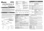
TTP 101 Kiosk Printer Installation Manual Publ. No.: 38-1201-00, Ed. B Related manuals • TTP 101 Technical Specification 38-1231-00 (old No. SWC-872) • TTP Operating Instructions 38 1211-00 (old No. SWC-811) • TTP 101 Service Manual 38-1221-00 (old No. SWC-811) Acknowledgments Adobe and Acrobat are trademarks of Adobe Systems Incorporated This is a publication of SWECOIN AB Box 132, S-191 22 Sollentuna, Sweden Phone int.+46 8 444 53 40 nat. Fax int. +46 8 96 50 54 nat. e-mail 08 444 53 40 08 96 50 54 [email protected] [email protected] www http://[email protected] © SWECOIN AB, 1996 All rights reserved. Reproduction in whole or in parts is prohibited without written consent of the copyright owner. We have taken great care to ensure that the information in this manual is correct and complete. However, if you discover any errors or omissions, or if you wish to make suggestions for improvements, you are welcome to send your comments to us. SWECOIN AB disclaims any liability resulting from the use of this information and reserves the right to make changes without notice. Second edition, August 1997 Printed in Sweden 2 TTP 101 Kiosk Printer – Installation Manual 9708 CONTENTS 1 INTRODUCTION.............................................................................................................. 3 1.1 About this manual .......................................................................................... 3 1.2 Updating......................................................................................................... 3 2 PRODUCT PRESENTATION .......................................................................................... 4 3 SUMMARY OF CONTROL CODES & ESCAPE SEQUENCES ..................................... 5 3.1 Character and bit-image graphics commands............................................... 5 3.2 Label- and other top-of-form-oriented commands ......................................... 6 4 SOFTWARE COMMAND SYNTAX ................................................................................. 7 4.1 Character and bit-image-graphics commands............................................... 7 5 LABEL- AND OTHER TOP-OF-FORM ORIENTED PRINT.......................................... 14 6 ERROR CODES............................................................................................................. 23 7 PRINTER INTERFACES................................................................................................ 24 7.1 Control board SWC-842 .............................................................................. 25 7.1.1 Paper feed switch connector .......................................................... 25 7.1.2 Paper-low switch connector............................................................ 26 7.1.3 Serial interface................................................................................ 26 7.1.5 Parallel interface ............................................................................. 27 7.1.6 Power supply interface ................................................................... 27 7.2 Control board SWC-642 .............................................................................. 29 7.2.1 Paper feed switch ........................................................................... 30 7.2.2 Serial interface................................................................................ 30 7.2.4 Parallel interface ............................................................................. 31 7.2.5 Power supply interface ................................................................... 32 8 TEST PRINT FUNCTIONS ............................................................................................ 33 8.1 Self test off-line printout ............................................................................... 33 8.2 HEX dump, on-line printout.......................................................................... 34 9 BASIC CHARACTER SET............................................................................................. 35 10 NATIONAL CHARACTER SETS ................................................................................. 36 11 FIRMWARE HISTORY................................................................................................. 37 12 INSTALLATION CONSIDERATIONS.......................................................................... 38 9708 TTP 101 Kiosk Printer – Installation Manual 1 REGISTER NOW! Please fill in the registration form inserted at the end of this manual and return it to us through mail or fax. This will put you on our mailing list for keeping you informed of product changes, manual updates etc. Registration date (for your own records): REVISION HISTORY Page Back of title page Change Publication numbers changed TTP 101 Operating Instructions added. Phone number changed, e-mail and web site addresses added. 3 Section 1.2: Information about BBS replaced by references to web site. 5 Commands ESC ENQ 2 and ESC ENQ 5 added. 7 Description of commands LF and CR modified. 9 Command ESC ENQ 2 added. 10 Command ESC ENQ 5 added 23 Note added 24 — 28 2 New control board SWC-842 added 29 Second paragraph: Connector J13 changed to J12 (typing error) 37 Firmware versions 1.18 — 1.20 added 38 Section Installation Considerations added TTP 101 Kiosk Printer – Installation Manual 9708 1 INTRODUCTION 1.1 About this manual This manual contains the information required for installation of the printer and to run it from a host computer such as a PC. The first chapter summarizes the applicable control codes and escape sequences supported by the printer processor firmware. The summary is followed by chapters describing the command syntax. Other chapters of the manual contain information about the printer error codes, communications parameters, test print functions, specifications of the serial and parallel printer interfaces, etc. This edition of the manual is valid for TTP 101 printers with serial number starting from 8506. 1.2 Updating This manual will be updated as, from time to time, printer functions and features may be added or amended. You will always find the latest edition on our web site (http://www.swecoin.se). Printed copies of the current manual edition can be ordered by email, fax or phone. Registered manual owners will be kept informed about new editions, product changes, etc. through our fax or e-mail bulletin service. To register as a manual owner, either fill in the form at the end of the manual or fill in the requested information when you visit the Technical Support section on our web site to download a manual. If you require functions not found in the manual edition at your disposal, you are welcome to consult one of our offices for information. 9708 TTP 101 Kiosk Printer – Installation Manual 3 2 PRODUCT PRESENTATION Figure 1. Printer exterior 4 TTP 101 Kiosk Printer – Installation Manual 9708 3 SUMMARY OF CONTROL CODES & ESCAPE SEQUENCES 3.1 Character and bit-image graphics commands Command Hex. Decimal Function LF 0A 10 Line feed 7 CR 0D 13 Carriage return 7 FF 0C 12 Form feed 7 RS 1E 30 Cut and eject paper 8 SI 0F 15 Reset from double-width print mode 8 SO 0E 14 Set double-width print mode 8 ENQ 05 5 Clear presenter 8 CAN 18 24 Clear input buffer 8 ESC @ 1B 40 27 64 Reset, initialize 9 ESC C n1 n2 1B 43 n1 n2 27 67 n1 n2 Set page length 9 ESC ENQ 1 1B 05 01 27 5 1 Status inquiry 9 ESC ENQ 2 1B 05 02 27 5 2 Status enquiry, paper near end, serial 9 ESC ENQ 5 1B 05 05 27 5 5 Status enquiry, paper near end, parallel 10 ESC FF n 1B 0C n 27 12 n Eject only (after cut) 10 ESC f n 1B 66 n 27 102 n Presenter motor drive 10 ESC J n 1B 4A n 27 74 n Paper advance 10 ESC l n 1B 6C n 27 108 n Line feeds before cut 11 ESC M n1 n2 1B 4Dn1 n2 27 77 n1 n2 Top-of-form detection 21 ESC p nnnn 1B 70 nnnn 27 112 nnnn Custom logotype print 11 ESC q n 1B 71 n 27 113 n Burn time adjustment 11 ESC R n 1B 52 n 27 82 n Select national character set 12 ESC RS 1B 1E 27 30 Cut only, no eject 12 ESC S n1 n2 1B 53 n1 n2 27 83 n1 n2 Select graphics mode 12 ESC SI 1B 0F 27 15 Reset from double height 13 ESC SO 1B 0E 27 14 Set double height print 13 ESC T n 1B 54 n 27 84 n Reversed print on/off 13 9708 TTP 101 Kiosk Printer – Installation Manual Page 5 3.2 Label- and other top-of-form-oriented commands Command Hex. Decimal Function ESC A n1n2n3 1B 41 n1n2n3 27 65 n1n2n3 Set document length 14 ESC BC b1 1B 42 43 b11 27 66 67 b1 Clear bar code area 14 ESC BS b1...b11 1B 42 53 b1...b11 27 66 83 b1...b11 Reset bar code block 15 ESC BW b1..NUL 1B 42 57 b1...00 27 66 87 b1...0 State bar code data 16 ESC DC d1 1B 44 43 d1 27 68 67 d1 Clear comment area 17 ESC DS d1...d7 1B 44 53 d1...d7 27 68 83 d1...d7 Reserve comment block 17 ESC DW d1..NUL 1B 44 57 d1...00 27 68 87 d1...0 Comment block data 18 ESC E 1B 45 27 69 Clear all label areas 18 ESC GC g1 1B 47 43 g1 27 71 67 g1 Clear graphics area 18 ESC GS g1...g8 1B 47 53 g1...g8 27 71 83 g1...g8 Reserve graphics area 19 ESC GW g1...gn 1B 47 57 g1...gn 27 71 87 g1...gn Graphics data 19 ESC LC l1 1B 4C 43 l1 27 76 67 l1 Clear ruler line area 20 ESC LS l1...l10 1B 4C 43 l1...l10 27 76 83 l1...l10 Ruler line data 20 ESC P n1 1B 50 n1 27 80 n1 Print document (label) 21 ESC X n1 n2 1B 58 n1 n2 27 88 n1 n2 Sense top-of-form position 22 ESC Y n1 n2 1B 59 n1 n2 27 89 n1 n2 Set start position 22 6 TTP 101 Kiosk Printer – Installation Manual Page 9708 4 SOFTWARE COMMAND SYNTAX 4.1 Character and bit-image-graphics commands LF Line feed (0AH), (10) decimal Prints the data in the input buffer in the current character mode and advances the paper according the selected character height (normal or double height set with commands ESC+SI and ESC+SO, page 13). The command is ignored if immediately preceded by a CR. CR Carriage return (0DH), (13) decimal Prints the data in the input buffer in the current character mode and advances the paper according the selected character height (normal or double height set with commands ESC+SI and ESC+SO, page 13). If the input buffer contains only line space data, line feed is effected. If the buffer contains no data the printer does not react to this command. FF Form feed (0CH), (12) decimal Prints the data from the input buffer and feeds the paper to the top of the next page as specified with command ESC+C+n1+n2 (see page 9). The TTP 101 is placed in continuous print mode when turned ON or reset (command ESC @, see page 9). This also sets page length = 0, print lines = 0, and skip lines = 0). 9708 TTP 101 Kiosk Printer – Installation Manual 7 RS Record separate (1EH), (30) decimal Cuts the paper and feeds it until the presenter feed rolls pick up the paper edge. For other eject lengths, use command combination ESC+RS (page 12) and ESC+FF (page 10). SI Shift in (0FH), (15) decimal Resets from double-width mode, set by command SO, to normal width mode. Valid in double-width mode only. SO Shift out (0EH), (14) decimal Sets double-width mode. The characters are printed in double width. Normal-width and double-width characters can be combined on the same print line. Double-width mode can be combined with double-height mode for printing of "quadruple" characters. ENQ Clear presenter and report status (05H), (5) decimal Used to clear the paper path in the presenter, for example, to eject a document not removed during the previous print/cut/eject operation. Status code ACK is returned as a result of a successful clearing. Error code NAK+01 means that the clearing failed. Also see Chapter 6. CAN Cancel (18H), (24) decimal Cancels any data previously stored in the input buffer. Commands issued on the same line as the CAN command are not canceled. 8 TTP 101 Kiosk Printer – Installation Manual 9708 ESC+ @ Reset (1BH)+(40H), (27)+(64) decimal Terminates the processing and initializes the control board. The control board is reset to default values, same as at power ON. Do not use this command as part of print data command strings. ESC+C+n1+n2 Set page length (1BH)+(43H)+n1+n2, (27)+(67)+n1+n2 decimal Sets the page length valid in character mode. A page consists of a printable area followed by a skip area at the bottom of the page. The printable area equals the page length n1 minus the skip area n2. The command is ignored if n1 is smaller than n2 or equal to n2. The printer is put into continuous print mode if n1 = 0. n1 and n2 must be 1-byte hexadecimal or decimal numbers. The printer is placed in continuous print mode when turned ON or reset. ESC + ENQ + 1 Status inquiry (1BH)+(05H)+(01H), (27)+(5)+(1) decimal Status inquiry. Results in response ACK if all sensors are clear, NAK + code if one or more sensors report fault condition. See Chapter 6. Compare with ENQ command which also clears the presenter module. ESC + ENQ + 2 Status enquiry, paper near end (with serial interface) (1BH)+(05H)+(02H), (27)+(5)+(2) decimal This command requests a paper-near-end sensor (paper low) status from the printer in a 1-byte format. Value = (00H) indicates ”No paper” Value = (01H) indicates ”Paper present” at the sensor position 9708 TTP 101 Kiosk Printer – Installation Manual 9 ESC + ENQ + 5 Status enquiry, paper near end (with parallel interface) (1BH)+(05H)+(05H), (27)+(5)+(5) decimal This command requests a paper-near-end sensor (paper low) status from the printer in a 1-byte format as follows: Value = (00H) indicates ”No paper” Value = (01H) indicates ”Paper present” at the sensor position ESC + FF + n Eject only (1BH)+(0CH)+n, (27)+(12)+n decimal Usually follows an ESC + RS command. ESC+FF+n effects ejection of a previously cut-off document out of the presenter module. Parameter n represents the number of eject steps (maximum = 255), each one of approximately 2 mm length. The primary use of this command is to determine if a document is to be fully or partially ejected (partly retained in the presenter module) or to partially eject a long document during ongoing processing, also without a preceding cut command. ESC + f + n Presenter motor drive selection (1BH)+(66H)+n, (27)+(102)+n decimal ESC + J + n n=0 Default value. Presenter motor just catches the leading paper edge. If the printing continues, the paper will form an increasing loop until printing is completed. n=1 The leading paper edge is ignored by the presenter sensor and the paper is fed straight through the presenter module. This function can be turned on/off at any time during an ongoing operation. Paper advance (1BH)+(4AH)+n, (27)+(74)+n decimal The value n represents the number of dot lines (at 0.25 mm) at which the paper is to be transported forwards. Maximum value for n = 255, equal to approximately 32 mm. 10 TTP 101 Kiosk Printer – Installation Manual 9708 ESC + l + n Line feeds before cut (1BH)+(6CH)+n, (27)+(108)+n decimal Sets the number of line feeds to be executed before a cut-off. Valid only in combination with the RS command. ESC + p + nnnn Logotype print (1BH)+(70H)+nnnn, (27)+(112) nnnn decimal Effects print of customized logotype stored in EPROM. nnnn ESC + q + n Represents a four-digit number assigned to customized logotype. Burn time adjustment (1BH)+(71H)+n, (27)+(113)+n decimal Parameter n specifies the burn time for the thermal head resistors. This command adjusts the burn time to obtain the optimal print contrast with the paper quality in use. Each step n represents a pulse width adjustment of approximately 25 us. n = 5 or 10 Default value (see Note below) n = 1—15 Adjustment range. Adjustment should be done in small steps. NOTE! At power-ON, the firmware senses whether there is a solder jumper in position SW4 (standard) and, if so, presets the burn time parameter value to ESC q= 10. The jumper should always be installed when the printhead is supplied with +20 V. This is the case in all TTP 101 printers from serial number 8506 since they have a built-in +20 V regulator. With earlier printer versions, the solder jumper SW4 should be installed only if the printer control board is supplied with +20 V. If the supply voltage is between +20 V and +24 V, the solder jumper SW4 must be removed to prevent printhead damage. The burn time value will then be preset to the value ESC q = 5 at power-ON but can be adjusted with the ESC q command during printing 9708 TTP 101 Kiosk Printer – Installation Manual 11 SC + R + n Select national character set (1BH)+(52H)+n, (27)+(82)+n decimal Selects one of eight national character sets specified by n. Legitimate n values are listed below. Invalid values are ignored. Value 1 (USA) is set at power ON. n=1 USA n=2 Germany n=3 Great Britain n=4 France n=5 Spain n=6 Italy n=7 Sweden n=8 Denmark ESC + RS Cut paper (1BH) + (1EH), (27) + (30) decimal Effects paper cut-off only. Eject can be effected with the ESC + FF + n command (see page 10). ESC+S+n1+n2 Select graphics mode (1BH)+(53H)+ n1+n2, (27)+(83)+n1+n2 decimal Sets Bit Image Graphics Mode. n1 and n2 High and low order byte. Determine the number of dot lines. Both n1 and n2 must be 1-byte hexadecimal or decimal numbers The printer is put in character mode if n1 = n2 = 0 Of commands issued before the ESC+S, only Reversed Printing (ESC+T+n) remains valid after execution of the ESC+S command. In bit-image graphics mode, all ASCII character codes are interpreted and processed as bit-image data. Data overflowing the specified print area are printed as ASCII characters. If less data than specified is received, the printer may enter a wait state, expecting further data. The printer may handle subsequent character code, or non-bit-image data, as bit-image data. The host computer must therefore supply 24 x (n1n2) data bytes, that is, 24 bytes per line times the number of dot lines to be printed. 12 TTP 101 Kiosk Printer – Installation Manual 9708 ESC + SI Reset double-height mode (1BH)+(0FH), (27)+(15) decimal Resets the printer from double-height mode to normal-height mode (double-height mode was set with the ESC+SO command). Valid only in double-height mode. ESC + SO Set double-height mode (1BH)+(0EH), (27)+(14) decimal Places the printer in double-height mode, printing double-height characters. A print line cannot contain both normal-height and double-height characters, but double height can be combined with double width for "quadruple" characters. ESC + T + n Set reversed printing (1BH)+(54H)+n, (27)+(84)+n decimal Selects normal or reversed print mode. 9708 n=0 Gives normal print (black on white background) n=1 Gives reversed print (white on black background) TTP 101 Kiosk Printer – Installation Manual 13 5 LABEL- AND OTHER TOP-OF-FORM ORIENTED PRINT This section discusses software commands used to print documents using functions such as label printing, bar code printing, enlarged character printing (comment block), landscape printing, graphics, ruler line and related functions. ESC+A+n1+n2+n3 Set document (label) length (1BH)+(41H)+n1+n2+n3, (27)+(65)+n1+n2+n3 decimal Determines the length of the document (label) to be printed. The printer control board has approximately 6 K bytes of page memory available for data storage. With this page memory, the maximum available field length (lmax.) is 250 dot lines, equal to approximately 62 mm paper length. n1 Specifies block No. (0—15). The total available document length can be divided into a total of 16 blocks. The blocks must be defined sequentially, starting at No. 0. Any n1 value other than 0—15 is ignored. n2n3 Specifies effective document (label) length. n2 = high order, n3 = low order n2 and n3 are 1-byte hexadecimal or decimal numbers. The value specified by n2 and n3 must not exceed the maximum effective length specified above. This command may be omitted if the block to be printed is positioned in block No. 0 only. ESC + BC + b1 Clear bar code area (1BH)+"BC"+b1, (27)+"BC"+b1 decimal This command clears the bar code block area reserved by the command ESC + BS. b1 14 Specifies the bar code block No. (0—15). The blocks may be specified in any order but b1 values other than 0—15 are ignored. TTP 101 Kiosk Printer – Installation Manual 9708 ESC+BS+b1+b2+...+b11 Reserve bar code block area (1BH)+"BS"+b1+b2+...+b11, (27)+"BS"+b1+b2+...+b11 decimal Reserves a document block identified by the ESC + A command as a bar code area. The command also identifies the type, number of digits and the configuration of bars to be placed in the bar code area. b1 Specifies the bar code block No. (0—15). The blocks may be specified in any order. Any value other than 0—15 is ignored. b2b3 Specifies the X coordinate of the bar code block position. Parameter b2 is the higher order and b3 the lower order byte). Parameters b2 and b3 must be 1-byte hexadecimal or decimal numbers. The value specified by b2b3 must not exceed the total dot count (24 bytes) that can be handled by the printer mechanism. b4b5 Specifies the Y coordinate of the bar code block position. Parameter b4 is the higher order and b5 the lower order byte. Parameters b4 and b5 must be 1-byte hexadecimal or decimal numbers. The value specified by b4b5 must not exceed the effective length specified in the ESC+ A command. b6 Specifies the number of bar code digits. b7b8 Specifies the height of the bars. Parameters b7 and b8 must be 1-byte hexadecimal or decimal numbers. The value specified by b7 and b8 must not exceed the effective length specified in the ESC + A command. b9 Specifies the type of bar code. The following bar code types are supported. b9 = 0, EAN 13 and UPC-A (no sub-titles, insufficient space in nominal size) b9 = 1, EAN 8 b9 = 6, Code 39 b9 = 8, Code 128 b9 = 9, EAN 128 Note: For EAN codes, the printer calculates the necessary check digit. For Code 39, the start and stop character "*" is generated by the printer. For UPC-A, use b9 value = 0 and insert a prefix "0" before the 11-digit data string. 9708 TTP 101 Kiosk Printer – Installation Manual 15 b10 Specifies the thickness of the narrow bar. 0 = 1 dot 3 = not applicable 6 = 7 dots 1 = 2 dots 4 = 5 dots 7 = 8 dots 2 = 3 dots 5 = 6 dots All other values are invalid. For EAN bar codes, only values 0 and 1 apply b11 Specifies the ratio of wide bar to narrow bar. b11 value Narrow bar Wide bar 0 1 1,5 1 1 2 2 1 2,5 (may be difficult to read) 3 1 3 4 1 3.5 The lower three bits of the b11 byte are significant (some ratio values may not be processed properly). The above values serve only as guidance values. For EAN bar code, a fixed ratio applies. ESC+BW+b1+b2...+NUL State bar code data (1BH)+"BW"+b1+b2...+(00H), (27)+"BW"+b1+b2...+0 decimal Fills the bar code area reserved by the ESC+BS command with bar code data to be printed. b1 Specifies the block (0—15). Blocks can be specified in any order but other values than 0—15 are ignored. b2… Specifies bar code data bytes. NUL Must be placed at the end of the bar code data. Any invalid bar code character terminates the command. Print-out is effected by an ESC + P command. 16 TTP 101 Kiosk Printer – Installation Manual 9708 ESC+DC+d1 Clear comment block area (1BH)+"DC"+d1, (27)+"DC"+d1 decimal Clears the comment block area reserved by the ESC+DS command. d1 Specifies the comment block (0—15) to be cleared. Comment blocks can be specified in any sequence but other values than 0—15 are ignored. Of command codes specified before this command, only ESC+T+n (reverse printing) remains in effect after execution of ESC+DC+d1. ESC+DS+d1+d2+...+d7 Reserve comment block area (1BH)+"DS"+d1+d2..., (27)+"DS"+d1+d2... decimal Reserves a comment block area within a document length defined by the ESC+A command. The command also specifies the type, orientation and number of comment columns to be placed in the comment block area. d1 Specifies comment block number (0—15). Comment blocks can be specified in any sequence but other values than 0—15 are ignored. d2d3 Specifies the X coordinate of the comment block position, (d2 is the higher and d3 the low order byte). Parameters d2 and d3 must be 1-byte hexadecimal or decimal numbers. The value specified by d2d3 must not exceed the total dot count (24 bytes) that the printer mechanism can handle. d4d5 Specifies the Y coordinate of the comment block position, (d4 is the higher and d5 the low order byte) and must be expressed in 1-byte hexadecimal or decimal numbers. The value specified in d4d5 must not exceed the effective length specified in the ESC+A command. d6 Specifies the number of comment columns. d7 Specifies the size of the comment characters d7 Character size 0 24 x 16 dot matrix 1 24 x 32 dot matrix 2 48 x 16 dot matrix 3 48 x 32 dot matrix Only one type of character can appear in one comment block and only in portrait orientation. 9708 TTP 101 Kiosk Printer – Installation Manual 17 ESC+DW+d1+d2...+NUL State comment block data (1BH)+"DW"+d1+d2...+(00H), (27)+"DW"+d1+d2...+0 decimal Fills the comment block area reserved by the ESC+DS command with comment data. d1 Specifies the comment block number (0—15) that can be specified in any sequence. Values other than 0—15 are ignored d2... Specifies one or more comment data bytes NUL Must be placed at the end of the comment data. Any invalid command character terminates the ESC+DW command. Of commands specified before ESC+DW, only ESC+T+n (reverse printing) remains in effect after execution of the ESC+DW command. Print-out is effected by an ESC + P command. ESC + E Clear all label areas (1BH)+(45H), (27)+(69) decimal Clears all label areas. Of command codes specified before this command, only ESC+T+n (reverse printing), remains in effect after execution of ESC+E. ESC+GC+g1 Clear graphics area (1BH)+"GC"+g1, (27)+"GC"+g1 decimal Clears graphics block area reserved by the ESC+GS command. g1 Specifies graphics block (0—15) in any sequence. Values other than 0—15 are ignored. Of command codes specified before this command, only ESC+T+ (reverse printing) remains in effect after execution of ESC+GC. 18 TTP 101 Kiosk Printer – Installation Manual 9708 ESC+GS+g1+g2+...+g8 Reserve graphics block area (1BH)+"GS"+g1+g2+...+g8, (27)+"GS"+g1+g2+...+g8 decimal Reserves a block area defined in an ESC+A command as a graphics block area. The command also defines the size of the graphics block. g1 Specifies graphics block number (0—15). Graphics blocks may be specified in any order but values other than 0—15 are ignored. g2g3 Specifies X coordinate of the graphics block position. Parameter g2 is the high-order and g3 the low-order byte. Parameters g2 and g3 must be 1-byte hexadecimal or decimal numbers, and the value specified must not exceed 192 dots, the total dot count that can be handled by the printer mechanism. g4g5 Specifies the Y coordinate of the graphics block position. Parameter g4 is the high-order and g5 the low-order byte and they must be 1-byte hexadecimal or decimal numbers. The value specified by g4g5 must not exceed the effective length specified in the ESC + A command. g6 Specifies the number of bytes (maximum 24) in the X-direction g7g8 Specifies the number of lines in the Y-direction. Parameter g7 is the highorder and g8 the low-order byte. Parameter g7g8 must be 1-byte hexadecimal or decimal numbers. The value specified by g7g8 must not exceed the effective length specified by ESC+A. ESC+GW+g1+g2+...+gn State graphics data (1BH)+"GW"+g1+g2+...+gn, (27)+"GW"+g1+g2+...+gn decimal Fills the graphics block area reserved by the ESC+GS command with graphics data. g1 Specifies graphics block number (0—15) in any order. Other g1 values than 0—15 are ignored. g2... Graphics data. Number of data bytes g2....gn: (number of bytes in X direction) multiplied by number of lines in Y direction. All ASCII characters and control codes are invalid. The printer will process any code as bit image data. Any data overflowing the graphics block specified with command ESC+ GS is ignored. If less data than specified is received, the printer may either enter a wait state, waiting for further data, or it may handle subsequent character codes or non-bit-image data as bit image data. The host computer must supply as much data as specified by ESC+GS. Of command codes specified before this command, only ESC+T+n (reverse printing) remains in effect after execution of the ESC+GW command. Print-out is effected by an ESC + P command. 9708 TTP 101 Kiosk Printer – Installation Manual 19 ESC + LC + l1 Clear ruler line area (1BH)+"LC"+l1, (27)+"LC"+l1 decimal Clears ruler line area l1 Specifies ruler line No. (1—15) in any order. Values other than 0—15 are ignored. Of command codes specified before this command, only ESC+T+n remains valid after execution of this command. ESC+LS+l1+l2...+l10 Set ruler line data (1BH)+"LS"+l1+l2...+l10, (27)+"LS"+l1+l2+...+l10 decimal Draws a horizontal or vertical ruler line in the block area defined by the ESC + A command. The command also defines the thickness of the ruler line. 20 l1 Specifies the ruler line number (0—15) in any order. Values other than 0—15 are ignored. l2l3 Specifies the X coordinate of the ruler line starting point (l2 is the high-order and l3 the low-order byte). l2 and l3 must be 1-byte hexadecimal or decimal numbers. The value specified by l2 and l3 must not exceed the total dot count that can be handled by the printer. l4l5 Specifies the Y coordinate of ruler line starting point (l4 is the high-order and l5 the low-order byte). l4 and l5 must be 1-byte hexadecimal or decimal numbers and the value specified by l4l5 must not exceed the effective length specified in the ESC + A command. l6l7 Specifies the X coordinate of the end of the ruler line (l6 is the high-order and l7 the low-order byte). l6 and l7 must be 1-byte hexadecimal or decimal numbers and the value specified by l6l7 must not exceed the total dot count that can be handled by the printer mechanism. l8l9 Specifies the Y coordinate of the end of the ruler line (l8 is the high-order and l9 the low-order byte). l8 and l9 must be 1-byte hexadecimal or decimal numbers. The value specified by l8l9 must not exceed the effective length specified in the ESC + A command. l10 Specifies the thickness of the ruler line: 0 = 1 dot 3 = 4 dots 6 = 7 dots 1 = 2 dots 4 = 5 dots 7 = 8 dots 2 = 3 dots 5 = 6 dots TTP 101 Kiosk Printer – Installation Manual 9708 The lower 3 bits of the l10 byte are significant. l2l3 must be smaller than l6l7. l4l5 must be smaller than l8l9. Any invalid parameter combination is ignored. The printer cannot draw slanted lines Of commands specified before the ESC + LS command, only ESC + T (reversed printing) remains in effect after execution of ESC + LS. Print-out is effected by an ESC + P command. ESC + M+n1+n2 Top-of-form detection (1BH)+(4DH)+n1+n2, (27)+(77)+n1+n2 decimal Identifies maximum (n1) and minimum (n2) length respectively of the TOF (Top-of-Form) mark printed on the reverse side of the paper. The length is expressed in dot lines at 0.25 mm. The TOF mark is used for identification of the top-of-form for the next document. Active transition is from ”black” to ”white”. n1 maximum valid value is 160 dot lines (20 mm) n1 minimum valid value is 15 dot lines (1.8 mm) n1 Default value = 30 dot lines at 0.25 mm n2 Default value = 12 dot lines at 0.25 mm. ESC + P + n1 Print document (label) (1BH)+(50H)+n1, (27)+(80)+n1 decimal Prints a document (label). n1 Specifies document number (0—15) of the document (label) to be printed. n1 value = <7FH> (or decimal <127>) specifies that all document (label) areas are to be printed (approximately 50 Kbytes of page memory). Any n1 value other than those indicated here are ignored. 9708 TTP 101 Kiosk Printer – Installation Manual 21 ESC + X + n1 + n2 Sense top-of-form position (1BH)+(58H)+n1+n2, (27)+(88)+n1+n2 decimal Reports if a TOF (Top-Of-Form) marker is sensed within the area specified by n1n2, starting at the current position. n1n2 ESC + Y + n1 + n2 Specifies the area to be searched for TOF marker. n1 is the high-order and n2 the low-order byte. Parameter n1n2 must be 1-byte hexadecimal or decimal numbers. Set document (label) starting position (1BH)+(59H)+n1+n2, (27)+(89)+n1+n2 decimal Defines the number of dot lines between the top of form position and the position at which the printing is to start. The printer advances the paper by the number of dot lines specified in this command before printing starts. n1n2 Specifies the number of dot lines by which the paper is to be transported forwards before printing starts. n1 is the high-order and n2 the low-order byte. n1 and n2 must be 1-byte hexadecimal or decimal numbers. The printer returns error code NAK+03 (see Chapter 6) if a paper-out condition occurs while the printer is feeding the paper as specified by n1n2 in this command. The paper feed length specified by n1n2 must be greater than or equal to the width of the TOF marker. The printer will return error code NAK+03 if the paper feed length is less than the width of the TOF marker (in paper transport direction). 22 TTP 101 Kiosk Printer – Installation Manual 9708 6 ERROR CODES The printer is equipped with a number of sensors that report the printer status and various error conditions such as out-of-paper, previous printout not removed, etc. In serial interface applications, the software commands ENQ and ESC ENQ 1 can be used to obtain status codes from the printer. Sending an ENQ (05H) Clear Presenter and Report Status, to the printer, results in the printer sending a status report to the host computer. This status report reflects the status of the available sensors in the printer and identifies possible error conditions. The table below shows the status report obtained as a response to the ESQ command. Status/error code Meaning ACK OK (printer is operable) NAK + 01 Paper left in presenter module. Attempt to clear the paper path failed. NAK + 02 Cutter not in home position NAK + 03 Printer out of paper NAK + 04 Print head lifted A status inquiry command can only return one status code at a time. If there are two or more simultaneous errors, each error condition should be cleared and the status inquiry repeated in order to get a complete report of all status codes. The host computer cannot be certain that all error conditions have been cleared until an ACK is received. The possible error conditions are reported in the above order. NOTE! NAK + error code will always be generated automatically when someone raises the paper release lever (printhead lifted) and when the printer runs out of paper (paper end). 9708 TTP 101 Kiosk Printer – Installation Manual 23 7 PRINTER INTERFACES For optimum mounting flexibility, the printer control board is designed as a separate module. The control board can be placed at a distance of up to approximately 0.35 m from the printer and connects to the printer by means of a flat cable (part number 900774-000). Figure 2. Printer interfaces, control board SWC-842 Figure 3. Printer interfaces, control board SWC-642 (previous design) 24 TTP 101 Kiosk Printer – Installation Manual 9708 7.1 Control board SWC-842 The following figure shows the SWC-842 control board connectors. Figure 4. SWC-842 control board connectors NOTE! Paper feed switch paper-low sensor are not included with the printer. 7.1.1 Paper feed switch connector A paper feed switch (normally open) should be connected to J10 (2.54 mm grid) on the SWC-842 control board. Figure 5. Paper-feed switch interface 9708 TTP 101 Kiosk Printer – Installation Manual 25 7.1.2 Paper-low switch connector A paper-low sensor can be connected to J16. Figure 6. Paper-low sensor interface 7.1.3 Serial interface The following table shows the pin assignment of the 9-pin D-sub connector J3: J3 Signal name Direction Description 2 RXD To printer Receive data 3 TXD From printer Transmit data 4 DTR — Data terminal ready 5 GND — Ground 7 RTS From printer Request to send The printer indicates that it is powered ON by setting DTR high. When initialized, RTS will be set high to indicate to the host that the printer is ready to receive data. RTS will be set low when the receive buffer is almost full, thereby telling the host to stop sending data until RTS is pulled high again. The serial interface communication protocol and handshaking parameters are as follows: Data format 8 data bits, 1 start bit, 1 stop bit, no parity (fixed) Transmission speed 9600 baud (fixed) Handshaking Hardware (RTS/CTS) and software (XON/XOFF) NOTE! Hardware and software handshaking are both active at all times. This allows the use of either of them depending on the configuration of the communication cable between printer and host. 26 TTP 101 Kiosk Printer – Installation Manual 9708 7.1.5 Parallel interface The following table shows the pin assignment in the 36-pin Amphenol connector J1 on the SWC-842 control board. Signal names starting with a "/" are active LOW signals. The signal timing emulates the Centronics-type parallel printer interface. J1 Signal Description 1 /STROBE To printer Strobe signal 2 D0 To printer Data bit 0 3 D1 To printer Data bit 1 4 D2 To printer Data bit 2 5 D3 To printer Data bit 3 6 D4 To printer Data bit 4 7 D5 To printer Data bit 5 8 D6 To printer Data bit 6 9 D7 To printer Data bit 7 10 /ACK From printer Acknowledge signal 11 BUSY From printer Busy signal 12 Paper out From printer Paper out signal 13 /ERROR From printer Error signal 19—30 GND 31 /Init To printer Printer initialization 32 /ERROR From printer Error signal 33—35 7.1.6 Direction GND Power supply interface Power to the printer is to be supplied through SWC-842 control board connector J2 . Connector type: MOLEX KK, 2.54 mm grid 9708 Pin Function Pin Function 1 +5 VDC 4 +24 VDC 2 GND 5 GND 3 +24 VDC 6 GND TTP 101 Kiosk Printer – Installation Manual 27 Voltage Print mode Current +24 VDC Standard text encoding/printing 2A average +24 VDC All black printing 6A (35% duty cycle) +5 VDC 300 mA CAUTION ! The order in which the +5 VDC and +24 VDC are established on the printer control board is essential. The + 5 VDC must be established before the + 24 VDC drive voltage is brought to the board (and vice versa at power-off). Otherwise, there is a risk of damaging both the printer control board and the thermal print head. Power supply units for evaluation purposes are available from Swecoin Promakon AB. 28 TTP 101 Kiosk Printer – Installation Manual 9708 7.2 Control board SWC-642 The figure below shows the connectors on the SWC-642 control board (a previous design). If the printer is connected through a flat cable to J13, the other connectors (except J12 and, possibly, J10) should not be used. J1 Print head thermistor J2 Power supply J12 Paper feed switch (normally open, 2.54 mm grid) J4 Print module motor J13 Printer (through 50-pole flat cable, replaces all connectors J6 Cutter motor J7 Presenter motor J11 Print head lifted sensor except J12 and, possibly, J10) J14 Print head J8 Paper end sensor J15 Serial interface, TTL-level J9 Presenter sensor J16 Parallel interface pin ramp J10 Paper-low sensor (optional) Figure 7. Control board SWC-642 9708 TTP 101 Kiosk Printer – Installation Manual 29 7.2.1 Paper feed switch A paper feed switch (normally open) should be connected to connector J12 (2.54 mm grid) on the SWC-642 control board. 7.2.2 Serial interface The SWC-642 control board has a 5-pole serial interface connector (J15) with TTL-level signals. An RS232 (V.24) serial interface adapter with a standard male 9-pin D-sub connector (see Figure 3) is available (part number 75-4008-00). The adapter is included if the printer version adapted for the RS 232 serial interface is ordered. The following table shows the pin assignment of J15 and the 9-pin D-sub connector: Conn. J15 9-pin D-sub Signal name 1 Direction +5V Description Power to interface adapter 2 3 TXD From printer Transmit data 3 2 RXD To printer Receive data 4 4 DTR From printer Data terminal ready 5 5 GND 7 RTS Ground From printer Request to send The printer indicates that it is powered ON by setting DTR high. When initialized, RTS will be set high to indicate to the host computer that the printer is ready to receive data. RTS will be set low when the receive buffer is almost full, thereby telling the computer to stop sending data until RTS is pulled high again. The following table shows alternative ways of designing an interface cable to be connected between a PC and J15 on the printer control board or between a PC and the serial adapter D-sub connector. Printer (J15 or serial adapter D-sub conn.) 30 PC Circuit Circuit 25-p. D-sub 9-p. D-sub RXD TXD 2 3 TXD RXD 3 2 RTS CTS 5 8 DTR DSR 6 6 GND GND 7 5 TTP 101 Kiosk Printer – Installation Manual 9708 The serial interface communication protocol and handshaking parameters are as follows: Data transfer rate 9600 baud (fixed) Data format 8 data bits, 1 start bit, 1 stop bit, no parity (fixed) Hardware handshaking RTS/CTS Software handshaking XON/XOFF NOTE! Both hardware and software handshaking are active at all times and, therefore, allow the use of either of them depending on the configuration of the communication cable between the printer and the host. 7.2.4 Parallel interface Operating the printer through the parallel interface of the SWC-642 control board can be done through the single-in-line connector J16, but is facilitated by the use of a parallel interface adapter with a 36-pole Amphenol connector (see Figure 3). The adapter (part number 75-0775-000) is to be mounted on to connector J16. The adapter is included if the printer order specifies the version adapted for parallel interface. The following table shows the pin assignment of J16 and the corresponding poles in the 36-pin Amphenol connector. Signal names starting with a "/" are active LOW signals. The signal timing emulates the Centronics-type parallel printer interface. (The table continues on the next page) Pin ramp J16 9708 Centronics Signal Direction Description 1 +24V To printer Should not be used 2 GND 3 +5V Should not be used To printer Should not be used 4 19—30, 33—35 GND 5 1 /STROBE To printer Strobe signal 6 2 D0 To printer Data bit 0 7 3 D1 To printer Data bit 1 8 4 D2 To printer Data bit 2 9 5 D3 To printer Data bit 3 10 6 D4 To printer Data bit 4 11 7 D5 To printer Data bit 5 12 8 D6 To printer Data bit 6 13 9 D7 To printer Data bit 7 TTP 101 Kiosk Printer – Installation Manual 31 Pin ramp J16 7.2.5 Centronics Signal Direction Description 14 10 /ACK From printer Acknowledge signal 15 11 BUSY From printer Busy signal 16 12 Paper out From printer Paper out signal 17 13, 32 /ERROR From printer Error signal 18 31 /Init To printer Printer initialization Power supply interface Power to the printer is to be supplied through SWC-642 control board connector J2 . Connector type: MOLEX KK, 2.54 mm grid Pin Function Pin Function 1 +5 VDC 4 +24 VDC 2 GND 5 GND 3 +24 VDC 6 GND Voltage Print mode Current +24 VDC Standard text encoding/printing 2A average +24 VDC All black printing 6A (35% duty cycle) +5 VDC 300 mA CAUTION ! The order in which the +5 VDC and +24 VDC are established on the printer control board is essential. The + 5 VDC must be established before the + 24 VDC drive voltage is brought to the board (and vice versa at power-off). Otherwise, there is a risk of damaging both the printer control board and the thermal print head. Power supply units for evaluation purposes are available from Swecoin Promakon AB. 32 TTP 101 Kiosk Printer – Installation Manual 9708 8 TEST PRINT FUNCTIONS The following two types of test prints can be obtained: • Off-line self test printout • On-line HEX dump (printout) of data transfer The two printout alternatives described below apply to a printer having a paper feed switch button connected to the control board. See Figure 4 and Figure 7 for connector number and position. If there is no paper feed button installed (during maintenance for example), short circuiting the connector pins will have the same effect as pressing the button. 8.1 Self test off-line printout 1. Verify that the power to the control board is switched OFF. 2. Push the paper feed button and keep it depressed. 3. Switch the power ON and keep the paper feed button depressed for at least 5 seconds. This produces a printout showing the firmware program (PROM) version, number of dots in the printhead, burn time, maximum characters per line, and (repeatedly) all characters in the character generator. 4. Release the paper feed button to stop the printing. The printer cuts and ejects the document, but remains in the self test mode. Renewed actuation of the paper feed button produces a demo test print-out followed by cut and eject. 5. Exit the self test mode by switching the power OFF. Note! — The printer is off-line and cannot receive any data while in the self test mode. 9708 TTP 101 Kiosk Printer – Installation Manual 33 8.2 HEX dump, on-line printout This function makes it possible to analyze the data received by the printer which should be very valuable during the design of the application software. Use the following procedure to change the printer mode: 34 1. Verify that the power is switched OFF. 2. Lift the print head release lever to upright position. 3. Depress the paper feed button and keep it depressed. 4. Power ON the printer. 5. Release the paper feed button. 6. Lower the print head release lever. The printer is now in a HEX dump mode and all on-line communication will be printed in both HEX format and ASCII character format on each line. 7. Depress the paper feed button temporarily. This ensures that the last transmitted characters are printed. The printer cuts the paper and feeds it out. 8. Exit from the HEX dump mode by switching the printer OFF. Switch the power ON again to resume normal on-line operation. TTP 101 Kiosk Printer – Installation Manual 9708 9 BASIC CHARACTER SET The table below shows the basic characters stored in PROM on the printer control board. The characters in the shaded positions can be substituted with characters from one of several national character sets. See page 36. Hex (1st digit) 0 1 2 3 4 5 6 Hex. (2nd digit) Dec. value (horiz. + vert.) 0 16 32 48 64 80 96 0 0 0 3 P 8 p Ç É á ä º Ù ª ² 1 1 ! 1 A Q a q ü æ í ã ¿ Õ ß ± 2 2 ” 2 B R b r é Æ ó å ¾ Ö § 3 3 1 3 C S c s â ô ú · ¼ Ê 4 4 2 4 D T d t ä ö ñ ½ ¶ É ´ 5 5 % 5 E U e u à ò Ñ Ò À Ã µ 6 6 & 6 F V f v å û ª Ó Ï Ä µ ÷ 7 7 ´ 7 G W g w ç ù º Ç Ð Ü ® 8 8 ( 8 H X h x ê ÿ ¿ Æ Ë Û © ° 9 9 ) 9 I Y i y ë Ö ³ Ô Å » ¨ A 10 * : J Z j z è Ü ¬ Â Ú ¸ · B 11 + ; K 4 k 9 ï ø ½ È × à « C 12 , < L 5 l 10 î £ ¼ Î Ñ ß ¯ D 13 - = M 6 m 11 ì Ø ¡ Í Á á ² E 14 . > N 7 n 12 Ä Pt « Ì Ý â ¬ æ F 15 / ? O _ o ∆ Å ƒ » ¹ Ø Þ ± 9708 7 8 9 A B C D E F 112 128 144 160 176 192 208 224 240 TTP 101 Kiosk Printer – Installation Manual 35 10 NATIONAL CHARACTER SETS This table lists national substitute characters stored in PROM on the printer control board. The position numbers refer to the shaded cells in the table showing the basic character sets. See page 35. The applicable character set is selected with the ESC+R+n command. 1 2 3 4 5 6 7 8 9 10 11 12 Hex. 23 24 40 5B 5C 5D 5E 60 7B 7C 7D 7E Dec. 35 36 64 91 92 93 94 96 123 124 125 126 USA # $ @ [ \ ] ^ ` { | } ~ France # $ à ° ç § ^ ` é ù è ¨ Germany # $ § Ä Ö Ü ^ ` ä ö ü ß Great Britain £ $ @ [ \ ] ^ ` { | } ~ Denmark # $ @ Æ Ø Å ^ ` æ ø å ~ Sweden # ¤ É Ä Ö Å Ü é ä ö å ü Italy # $ @ ° \ é ^ ù à ò è ì Spain ° $ @ ¡ Ñ ¿ ^ ` " ñ } ~ Pos. No. Character set 36 TTP 101 Kiosk Printer – Installation Manual 9708 11 FIRMWARE HISTORY Functions and features are being added from time to time affecting the firmware in the TTP 101. The following table lists the changes of general interest. Notice that the list may not contain the latest firmware versions. Please visit our web site http://www.swecoin.se. for current information. You can also download the latest firmware version from the Swecoin web site. FW version Change 1.13 First version released to customer. 1.14 Small modification of burn-time. 1.15 Bar code type 128 added.. 1.16 With earlier FW versions, it could happen that the print height became reduced when the printer got extremely hot. This was caused by a problem in the stepper motor drive IC. The problem was solved with a minor modification of the firmware. 1.17 At power-ON, the firmware senses whether there is a solder jumper in position SW4 (standard) and, if so, presets the burn time parameter value to ESC q= 10. The jumper should always be installed when the printhead is supplied with +20 V. This is the case in all TTP 101 printers from serial number 8506 since they have a built-in +20 V regulator. With earlier printer versions, the solder jumper SW4 should be installed only if the printer control board is supplied with +20 V. If the supply voltage is between +20 V and +24 V, the solder jumper SW4 must be removed to prevent printhead damage. The burn time value will then be preset to the value ESC q = 5 at power-ON but can be adjusted by issuing the ESC q command during printing. Also see page 11. 1.18 Presenter motor speed increased to ensure proper paper edge pickup at graphics printout. 1.19 Danish characters included. Paper-low detection by using ESC ENQ 05H now supported for parallel interface. 1.20 An error in the ESC + ENQ + 01H function, causing only ACK messages to be reported, has been fixed. Command ESC + ENQ + 02H added. Syntax: (1BH)+(05H)+(02H), (27)+(5)+(2) decimal This command requests a paper-near-end sensor (paper low) status from the printer in a 1-byte format as follows: Value = (00H) indicates ”No paper” Value = (01H) indicates ”Paper present” at the sensor position Self test printout now indicates when jumper SW4 is installed. 9708 TTP 101 Kiosk Printer – Installation Manual 37 12 INSTALLATION CONSIDERATIONS The TTP 101 printer is designed to be installed in some kind of enclosure such as a self service kiosk. Preventing ESD and earth currents from affecting the printer operation requires proper connection of the printer chassis to protective earth through a mounting platform or through a separate earth conductor. Trouble free printer operation also requires that the printer is shielded from excessive ambient light. Such light might disturb the printer operation by cheating a couple of built-in opto sensors. Additional space is required for paper replenishment and paper jam removal. Consider mounting the printer on a movable platform so that the printer can be maintained outside the printer enclosure. 38 TTP 101 Kiosk Printer – Installation Manual 9708 User Registration Form 32-1201-00, Ed B After you have returned this registration form to us we will keep you informed of product changes, manual updates, etc. through our bulletin service. Do not return this form if you already have registered a previous edition of this manual. You may also use this form to inform us about changed registration data (name, address, phone No., etc.), but please tick the Changed information box in that case. ❏ New registration ❏ Changed information Name Organization Postal address /street, box, area, etc.) Zip / Postal code City State Country Telephone Fax E-mail Please return by mail to Swecoin Promakon AB Box 132 S-191 22 SOLLENTUNA Sweden or by fax to Int.: +46 8 96 50 54 Nat.: 08 96 50 54 9708 TTP 101 Kiosk Printer – Installation Manual 39 This page intentionally left blank. 40 TTP 101 Kiosk Printer – Installation Manual 9708