1
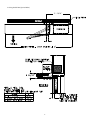
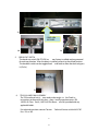
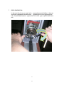
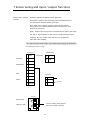
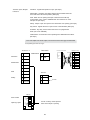
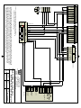
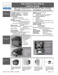
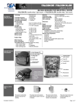
T-957 US801353
4-2-10
Installation and Service Manual
TDA SWING DOOR OPERATOR
1
Contents
1
Introduction
2
Safety
3-4
3
Installation 200 series
5-8
4
Installation 100 series
9 - 13
5
110vAC Connection
6
Teach In
15 - 16
7
Sensor wiring and input / output functions
17 - 22
8
Factory DirCom programming
23 - 29
9
Additional DirCom programming
30 - 35
10
Check List
3
14
36
2
1
Introduction
These instructions are intended for AAADM Certified technicinas. Tormax
strongly recommends all adjsstments be made in accordance
with ANSI A156.10 and A 156.19 standards.
Symbols Used in
these Instructions
These two symbols mark all passages that concern your safety:
Warning of a health hazard of a general kind
Warning of electric voltage/current
Passages with text on grey background must be absolutely observed for reliable
performance of the system! Neglect can cause material damage.
2
Before beginning the installation read the instructions in this manaul failure
to do so may cause serious injury to users or damage to the operator.
Make sure the door system is installed and serviced by an AAADM
certified technician to the latest ANSI A156.10 and or ANSI A156.19
standard.
These products are Underwriters Laboratories, Inc. (UL) listed and cUL certified
for the Canadian marketplace, and therefore comply with the requirements of the
National Electrical Code (NEC) and the Canadian Electrical Code (CEC). Installa
tions intended to meet UL and cUL requirements must be followed as described
in the instruction provided herein. These are minimum standard requirements.
Where local codes exceed these requirements, they must be followed as well.
-
The maximum leaf weight depends on the size of the door. Please proceed according
to the diagram below.
Lb
325
Maximum door weights
Door weight
General Safety Instruction
Safety
0
In
48
0
Leaf width
3
T1163/1e
3
Preventing General Hazards and Possible Damage to This Equipment
• Verify that the power selection switch is set to the correct voltage before start-up.
knockout that is close to the input power supply terminals. It should not be routed
structure. It should not also be concealed behind walls, etc.
parts of the operator, door, or system.
Warnings of Dangerous Electrical Voltages or Current
• Be sure the electrical power is disconnected and locked-out when working on the
operator unit.
• Install the electrical cables and power only after the mechanical installation to the unit
is done.
• Turn on the power to the operator unit only after all internal cables are connected. Do
not connect cables while the unit is powered.
• Always use appropriate tools for installation and repair.
General Safety and
Accident Prevention
Instructions
Please read the operating instructions of the TORMAX operator and the following safety
instructions carefully prior to commissioning or performing any work on the system—and
adhere to them!
Pay particular attention to the specially marked notes in these instructions (for an explanation of the symbols please refer to chapter 1)!
Use for Intended Purpose
The TORMAX operator has been designed and constructed according to the current
state of technology and the recognized safety related rules and is intended exclusively
for the usual application in conjunction with automatic TORMAX doors. The enclosure
operator corresponds to protective class IP22 . Without additional safety measures,
the operator may only be installed inside of buildings.
Any other use is considered incorrect and may result in injuries to the user or third parties. Further, it may result in damages to the system or other associated equipment.
The manufacturer will not be liable for damages resulting from incorrect application;
the risk of such applications must be borne entirely by the user.
Requirements Relating to
Installation Personnel
Tormax strongly recommends all service and installations be performed by an AAADM
Basic Safety Measures –
Appropriate Behavior
Use system only in a technically sound condition. Ensure that faults which could diminish safety are eliminated in at once.
Do not touch any moving parts. Extra caution is required in the areas of the drive lever,
the linkage and the secondary closing edges of the hinge.
Electrical voltage / current: perform manipulation cleaning only when the power supply
is switched off!
Connect mains supply only when all internal cables are connected.
Use only tools suited for the relevant work sequence, without exception. Make sure the
tools are in a sound condition.
Relevant Regulations
The operating, service and maintenance instructions supplied by the manu–facturer
must be observed. TORMAX door operators may only be maintained and repaired by
AAADM certified technicians.
4
3 Installation 200 series
Out Swing
5
0” Reveal In Swing
6
0 “- 6” In Swing Arm (RH SHown)
7
In Swing Parallel Arm (Speical Order)
11 - 13/16”
8
4 Installation 100 series
NOTE: Tormax recommends the use of a water level and and plumb bob
to proprley install any door package provided. An improper installation
could lead to premature weare of moving parts as well as an unpleasing
appeearance and / or service issues for the customer.
1.
TDA (Over Head Concealed) Installation
If the unit w as suppl ied with jambs they should be i nstalled at this time. If
the unit was supplied without jambs, then the un it should be secured into
the pr ovided locat ion us ing the appr opriate fasteners. The unit should be
installed so that outsi de forces acting on the door will not be able to move
or twist the unit, allowing the fasteners to work themselves loose.
TDA UNIT
FASTENERS
JAMB
9
2.
DRIVE ARM INSTALLATION
At this point install the drive ar m (PN TID 345026 )(Pic 2a) into the
splined output of the TDA Motor/Gear box assembly. This step should
be completed with no powe r supplied to the TDA.
The drive arm should be in serted so that two sides of the square boss run
as close to parallel to the header as the splines will allow (Pic. 2b).
The
location of the drive arm serves mu
ltiple purposes, it pre-loads the
door and also allows the door to br
eak out when equipped to do so.
The drive arm is designed to have an interference fit with the splines on
the TDA unit and thus should be driven into place. In sert the supplied
bolt (PN 140240-16) into the drive arm at least half way (Pic. 2c). Drive
the assembly into the TDA (Pic.2d). T he drive arm should be driven until
it bottoms. Once installed the drive arm must be secured with the
provided screw (M8 x 1.25 x 55 flat head). Insert as shown (Pic. 2e), into
the threaded bore in the TDA unit (Pic. 2f). The finished assembly can be
seen in (Pic. 2g).
2a
2b
2e
2c
2f
2d
10
10
2g
3.
INSTALLATION OF BOTT
OM GUIDE/ THRESHOLD
The bottom door pivot should now be installed along with the threshold if
required for this installation (Pic 3a). NOTE: The bottom doo r pivot is included
in PN STD.AKIS. The bottom door pi
vot must be in line with the drive arm
previously installed in the TDA. The use of a plumb bob to align the bottom
pivot is advised. If installed incorrectly, the door could swing in an
elliptical arc, resulting in ad
verse door characteristics.
3a
4.
DOOR INSTALLATION
Install the door from the side op posite the normal swing path (breakout side)
and at approximately 90 degrees to the TDA unit, place the door onto the
bottom pivot (Pic 4a & 4b). Line up the drive arm re ceiver with the drive arm
mounted to the TDA (Pic. 4c & 4d). NO
TE: The drive arm re ceiver is included
in PN STD.AKIS. Engage the door with
the drive arm and secure it with the
supplied cap and bolts (Pic. 4e).
Pictures contin ued on next page.
ENGAGE DOOR
4b
4a
INTENDED SWING PATH
BREAK OUT PATH
11
11
4c
DRIVE ARM
RECEIVER
4e
4d
5.
BREAK OUT SWITCH
The break out switch (PN STD.PKI) co
mes factory installed and programmed
for each ap plication. After the door is installed, rotate it to the closed position.
The breakout switch can be toggled back and forth to allow the door to bypass
it (Pic 5a).
5a
6.
TEACH IN AND FINAL ASSEMBLY
The TDA overhead unit is now ready to be taught in. See Teach In
instructions at the end of this docu ment. Install inspection covers (PN
140733-01 Clear finish, 140733-02 Drk Bronz e finish) provided and any
applicable labels.
For technical questions contact Tormax
Exts. 123 or 103.
12
12
Technical Service at 888-685-3707
7.
DRIVE ARM REMOVAL
In the event the dr ive arm needs to be removed proceed as follows. Lubricate
and insert supplied bolt into drive arm. Hold drive arm wh ile tightening the
bolt. Once the bolt bottoms against the TDA it will b egin to pull the drive arm
out.
13
13
5
Electrical Connections
10A T
L1
Note mains
voltage
Main System switch
3 mm
230/115 V
50/60 Hz
N
T957/9 e
Mains Connection
Prior to beginning any of the following work, ensure that the mains supply is turned
off.
The mains cable should be routed along the side containing the power supply if
possible.
The connections must be of type “PVC-cable H05VV-F” or “Rubber hose cable H05RRF” or material approved by local code.
Remove burrs from all feed-through holes for mains connections.
• Remove the mains supply cover (1).
• Connect the mains cable to terminal (K)
according to the figure.
• Route mains cable either through the prepared holes in the side part or through the
openings in the mounting plate.
L1
K
N
• Use only cable glands made from plastic material. Metallic bushings are to be
grounded..
S
• Secure mains cable with a cable strap on
the cable relief (Z).
1
Z
T957/8
• Check the correct setting of the voltage selector (S) and replace the mains supply
cover (1).
moving parts, the system can be connected to mains supply.
Cable Routing
The two cable straps fastened to the motor casing are used for the routing of external
cables.
• Remove both cable straps.
• Install emergency-off switch according to the contract order and route the mains
connection via the emergency-off switch.
Emergency-O Switch
Emergency-off switch
Mains connection TDA
L1
230 V
N
50/60 Hz
T957/1e
14
6 Teach - In
TDA Single / Master “Teach-In”
If required, the following basic adjustments of the door can be changed by the
“Teach-In” function:
SOFT KEY
Opening speed
Opening angle
Hold-open time (time delay)
Do not hold
soft key down
or programming
will be deleted!
“Teach-In” Procedure
1. Locate the small gray button (Soft-Key) on the TCP-52 control next to the wide
ribbon cable
NOTE: If the following steps take longer than 30 seconds each (except the
adjustment for the hold-open time), the control system will return to the
previously active operating mode (e.g. OFF, AUTO, HOLD-OPEN). The door
should be in the HOLD-OPEN position before proceeding to the next steps!
2. Select operating mode OFF.
3. Press and release the gray button.
4. The control will “beep” and the LED’s on the ON/OFF/HOLD-OPEN panel
will flash up and down. This signals that the Teach-In mode is activated.
5. The 2nd “beep” indicates the door is closed and the encoder is at the zero (0)
degree position.
6. Manually open the door to establish the opening speed and opening angle.
Hold the door in this position until the control “beeps” (3 rd beep).
7. After the 3rd “beep”, continue holding the door open to set the Hold-Open time.
8. Release the door after the desired Hold-Open time. When the door begins
closing, the control will “beep” a 4th time signaling that the Hold-Open time has
been set.
9. The control will “beep” a 5th time when the door is in the fully closed position.
10.Press and release the gray button. The control will “beep” a 6 th time
acknowledging the settings.
NOTE: After the door resets, it will open fully to the HOLD-OPEN
position.
1/26/04
15
Do not hold
soft key down
or programming
will be deleted!
PN: 408468 (Jumper Bee)
TDA Slave “Teach-In”
If required, the following basic adjustments of the door can be changed by the “Teach-In”
function:
Opening speed
Opening angle
Hold-open time (time delay)
Slave “Teach-In” Procedure
1. Unplug the power to the Slave control by disconnecting the transformer cable.
2. Plug the red Jumper Bee plug into the red socket on the Slave control next to the wide
ribbon cable as shown above. (This plug will be installed from the factory.)
3. Power the Slave control by reconnecting the transformer cable.
4. Put the function control panel on the Master in the “Automatic” position.
5. Locate the small gray button (Soft-Key) on the TCP-52 control next to the wide ribbon
cable.
NOTE: If the following steps take longer than 30 seconds each (except the adjustment
for the hold-open time), the control system will return to the previously active operating
mode (e.g. OFF, AUTO, HOLD-OPEN).
6. Press and release the gray button. This is the 1st “beep” for the Teach-In process.
7. The 2nd “beep” indicates the door is closed and the encoder is at the zero (0) degree
position.
8. Manually open the door to establish the opening speed and opening angle. Hold the
door in this position until the control “beeps” (3rd beep).
9. After the 3rd “beep”, continue holding the door open to set the Hold-Open time.
10. Release the door after the desired Hold-Open time. When the door begins closing, the
control will “beep” a 4th time signaling that the Hold-Open time has been set.
11. The control will “beep” a 5th time when the door is in the fully closed position.
12. Press and release the gray button. The control will “beep” a 6th time acknowledging the
settings. The door will slightly move while the control resets.
13. Remove the red Jumper Bee plug. Do not throw this plug away!!! It may be needed to
make future adjustments.
2/6/04
16
7 Sensor wiring and input / output functions
Terminal Input / Output
Functions
Activation - Signals the operator to open. (NO input)
Reactivation - Reopens door while closing input is inhibited when the
door reaches the full closed position. (NO input)
Stall - When door is opening and input is active the door will stop
in the position it is in. Input is inhibited when door reaches 75* of the
full open 90* (NO input)
Safety - Keeps a open door opena nd a closed door from opening. (NO input)
Key Switch - Signals the door to open even if in the Off Mode. (NO input)
E Module - Dry relay contact active when door is in programmed
state. (NO or NC avaliable)
.75 A max output from 24vdc output, use of 24vac trans is strongly recommended
Factory Wiring for TDA 200 Single
Terminal D
Ter minal C
Activation
Reactivation
Stall
Safety
1
GND
2
IN
3
GND
4
IN
5
+24 VDC
6
GND
7
IN
8
GND
9
IN
Key Switch
1
IN
2 GND
Terminal L
1
2
10 +24 VDC
GND
24 VDC
3
Opening / Open
OUT B
Door Closed
E14
E12
E11
OUT A
E-Module
E14
E12
E11
To lock out relay +24vdc present
when door is Open / Opening.
17
Terminal Input / Output
Functions
Activation - Signals the operator to open. (NO input)
Reactivation - Reopens door while closing input is inhibited when the
door reaches the full closed position. (NO input)
Stall - When door is opening and input is active the door will stop
in the position it is in. Input is inhibited when door reaches 75* of the
full open 90* (NO input)
Safety - Keeps a open door opena nd a closed door from opening. (NO input)
Key Switch - Signals the door to open even if in the Off Mode. (NO input)
E Module - Dry relay contact active when door is in programmed
state. (NO or NC avaliable)
Inhibit Switch - Prevents door from operating also called break out switch.
(NO input)
.75 A max output from 24vdc output, use of 24vac trans is strongly recommended
Factory Wiring for TDA 100 Single
Terminal D
Ter minal C
1
Activation
2
3
Reactivation
Stall
Safety
4
GND
Inhibit switch
IN
1
1
IN
Panel
lock
2 GND
GND
IN
5
+24 VDC
6
GND
7
IN
8
GND
9
IN
Terminal L
GND
2
10 +24 VDC
24 VDC
3
Opening / Open
OUT B
Door Closed
E14
E12
E11
OUT A
E-Module
E14
E12
E11
To lock out relay +24vdc present
when door is Open / Opening.
18
Screen
1
GND
2
2
IN
3
3
IN
4
4
IN
5
5
OUT
6
6
OUT
7
7
OUT
8
8
OUT
9
9
OUT
10
1
B Module on TCP
Function Control Panel
10 + 24 VDC
SAFETY SUPERSCAN
8
7
6
COM
5
N.O.
4
N.C.
3
INHIBIT +
1
EMPTY
8
POWER
7
POWER
6
COM
5
N.O.
4
N.C.
3
INHIBIT +
EMPTY
1
OFF
INHIBIT GND 2
ON
BLACK
RED
BODYGUARD
N.O.
green
COM
white
POWER
black
POWER
red
WHITE
POWER
GREEN
POWER
4
5
RED/WHITE
APPROACH SUPERSCAN
N.C.
2
3
1
GREY
LO21 DEFAULT DIP SWITCHES
ORANGE
SEE NOTE 2
INHIBIT GND 2
2
1
3
4
DATA + 7
blue
DATA - 6
brown
N.C.
5
IF AFTER TROUBLESHOOTING A PROBLEM, A SATISFACTORY SOLUTION CANNOT BE ACHIEVED, PLEASE CALL B.E.A., INC.
FOR FURTHER ASSISTANCE DURING EASTERN STANDARD TIME AT 1-800-523-2462 FROM 8AM - 5PM. FOR AFTER-HOURS,
CALL EAST COAST: 1-866-836-1863 OR 1-800-407-4545 / MID-WEST: 1-888-308-8843 / WEST COAST: 1-888-419-2564. DO NOT
LEAVE ANY PROBLEM UNRESOLVED. IF YOU MUST WAIT FOR THE FOLLOWING WORKDAY TO CALL B.E.A., LEAVE THE
DOOR INOPERABLE UNTIL SATISFACTORY REPAIRS CAN BE MADE. NEVER SACRIFICE THE SAFE OPERATION OF THE
AUTOMATIC DOOR OR GATE FOR AN INCOMPLETE SOLUTION.WEB: WWW.BEASENSORS.COM
TDA
1 GND
2 IN
CONTROL
3 GND
SINGLE
4 IN
5 +24 VDC
BASIC MODULE
6 GND
C
7 IN
8 GND
9 IN
10+24 VDC
IN 1
MODULE D
GND 2
SEE NOTE 1
E11
E MODULE 1
E12
RELAY A
E14
E11
E MODULE 1
E12 RELAY B
E14
100 ENTERPRISE DRIVE
PITTSBURGH, PA 15275
PHONE: (412) 249-4100
FAX:
(412) 249-4101
EMAIL: www.beasensors.com
NONE
SCALE:
DRAWN BY:
JED
21 JULY 2009
DATE:
REV BY:
1 OF 1
SHEET
PART NO:
80.0308.00
TITLE: TORMAX TDA SINGLE DOOR
WITH PARALLAX 1 SYSTEM (LO-21P)
SIZE:
A
19
N.O.
green
COM
white
POWER
black
POWER
red
RED
GREEN
BROWN
NOTES: 1.) SEE TORMAX INSTALLATION MANUAL FOR ASSISTANCE.
2.) ENSURE TO SET THE BODYGUARD RELAY TO VALUE 2. N.C.
3.) SEE LO21P USER GUIDE FOR ASSISTANCE
EAGLE
BLACK/WHITE
Terminal Input / Output
Functions
Activation - Signals the operator to open. (NO input)
Reactivation - Reopens door while closing input is inhibited when the
door reaches the full closed position. (NO input)
Stall - When door is opening and input is active the door will stop
in the position it is in. Input is inhibited when door reaches 75* of the
full open 90* (NO input)
Safety - Keeps a open door opena nd a closed door from opening. (NO input)
Key Switch - Signals the door to open even if in the Off Mode. (NO input)
E Module - Dry relay contact active when door is in programmed
state. (NO or NC avaliable)
.75 A max output from 24vdc output, use of 24vac trans is strongly recommended
Factory Wiring for TDA 200 Pair
Activation
Reactivation
Stall
Safety
Master
Ter minal C
Slave
Ter minal C
1
GND
1
GND
2
IN
2
IN
3
GND
3
GND
4
IN
4
IN
5
+24 VDC
5
+24 VDC
6
GND
6
GND
7
IN
7
IN
8
GND
8
GND
9
IN
9
IN
Off Mode
Reactivation
Stall
Activation
10 +24 VDC
10 +24 VDC
Terminal D
Key Switch
1
Terminal D
Safety
IN
2 GND
1
2 GND
E-Module
Door Closed
OUT B
E14
E12
E11
Door
Opening / Open
E14
E12
E11
OUT A
OUT B
Off Mode
E14
E12
E11
OUT A
E-Module
Open Mode
IN
E14
E12
E11
To lock out relay +24vdc present
when door is Open / Opening.
20
Terminal Input / Output
Functions
Activation - Signals the operator to open. (NO input)
Reactivation - Reopens door while closing input is inhibited when the
door reaches the full closed position. (NO input)
Stall - When door is opening and input is active the door will stop
in the position it is in. Input is inhibited when door reaches 75* of the
full open 90* (NO input)
Safety - Keeps a open door opena nd a closed door from opening. (NO input)
Key Switch - Signals the door to open even if in the Off Mode. (NO input)
E Module - Dry relay contact active when door is in programmed
state. (NO or NC avaliable)
Inhibit Switch - Prevents door from operating aslo called the break out switch. (NO input)
.75 A max output from 24vdc output, use of 24vac trans is strongly recommended
Factory Wiring for TDA 100 Pair
Activation
Master
Ter minal C
Slave
Ter minal C
1
1
2
3
Reactivation
Safety
Reactivation
IN
7
IN
8
GND
Stall
Activation
IN
IN
+24 VDC
GND
7
IN
8
GND
9
IN
IN
2 GND
E-Module
Door Closed
OUT B
E14
E12
E11
Door
Opening / Open
E14
E12
E11
OUT A
OUT B
E14
E12
E11
OUT A
E-Module
Off Mode
GND
6
1
2 GND
Open Mode
Panel
lock
Terminal D
Safety
IN
IN
1
Screen
1
GND
2
2
IN
3
3
IN
4
4
IN
5
5
OUT
6
6
OUT
7
7
OUT
8
8
OUT
9
9
OUT
10
10 + 24 VDC
Terminal F
Inhibit
Switch
Auxiliary
supply
Terminal D
1
GND
10 +24 VDC
10 +24 VDC
Inhibit Switch
4
5
+24 VDC
GND
2
3
GND
6
9
Off Mode
IN
4
5
Stall
GND
E14
E12
E11
B Module on TCP
Function Control Panel
1
GND
2
IN
3
GND
4
+24 VDC
OUT
5
GND
6
IN
7
IN
See Sercom or Sersoft
for programming input
options.
To lock out relay +24vdc present
when door is Open / Opening.
21
5
SAFETY SUPERSCAN
8
7
6
COM
5
N.O.
4
N.C.
3
INHIBIT +
1
EMPTY
8
POWER
7
POWER
6
COM
5
N.O.
4
N.C.
3
INHIBIT +
EMPTY
INHIBIT GND 2
INHIBIT GND 2
SEE
NOTE 2
BODYGUARD
GND
IN
1
2
4
DATA + 7
blue
DATA - 6
brown
N.C.
5
APPROACH SUPERSCAN
7
6
COM
5
N.O.
4
N.C.
3
INHIBIT +
INHIBIT GND 2
SAFETY SUPERSCAN
1
8
POWER
7
POWER
6
COM
5
N.O.
4
N.C.
3
INHIBIT +
INHIBIT GND 2
1
E11
E MODULE 1
E12
RELAY A
E14
E11
E MODULE 1
E12 RELAY B
E14
IN 1
MODULE D
GND 2
TDA
1 GND
2 IN
CONTROL
3 GND
SLAVE
4 IN
5 +24 VDC
BASIC MODULE
6 GND
C
7 IN
8 GND
9 IN
10+24 VDC
EMPTY
SEE
NOTE 1
POWER
E11
E12
E14
8
E MODULE 1
RELAY A
E11
E12
E14
POWER
GND 3
IN 4
+24 VDC 5
GND 6
IN 7
GND 8
IN 9
+24 VDC10
E MODULE 1
RELAY B
IN 1
MODULE D
GND 2
BASIC MODULE
C
TDA
CONTROL
MASTER
3
BLUE
2
1
GREEN
YELLOW
RED
BLACK
100 ENTERPRISE DRIVE
PITTSBURGH, PA 15275
PHONE: (412) 249-4100
FAX:
(412) 249-4101
EMAIL: www.beasensors.com
NONE
SCALE:
DRAWN BY:
WJR
04 DEC 2009
DATE:
REV BY:
1 OF 1
SHEET
PART NO:
80.0305.01
TITLE: TORMAX TDA SIMULTANEOUS PAIR
WITH PARALLAX 2 SYSTEM LO-21P
SIZE:
A
EMPTY
1
OFF
ON
N.O.
green
COM
white
POWER
black
POWER
red
RED/WHITE
POWER
WHITE
POWER
N.C.
4
3
GRAY
IF AFTER TROUBLESHOOTING A PROBLEM, A SATISFACTORY SOLUTION CANNOT BE ACHIEVED, PLEASE CALL B.E.A., INC.
FOR FURTHER ASSISTANCE DURING EASTERN STANDARD TIME AT 1-800-523-2462 FROM 8AM - 5PM. FOR AFTER-HOURS,
CALL EAST COAST: 1-866-836-1863 OR 1-800-407-4545 / MID-WEST: 1-888-308-8843 / WEST COAST: 1-888-419-2564. DO NOT
LEAVE ANY PROBLEM UNRESOLVED. IF YOU MUST WAIT FOR THE FOLLOWING WORKDAY TO CALL B.E.A., LEAVE THE
DOOR INOPERABLE UNTIL SATISFACTORY REPAIRS CAN BE MADE. NEVER SACRIFICE THE SAFE OPERATION OF THE
AUTOMATIC DOOR OR GATE FOR AN INCOMPLETE SOLUTION.WEB: WWW.BEASENSORS.COM
22
2
1
BLACK / WHITE
LO21P DEFAULT DIP SWITCHES
ORANGE
APPROACH SUPERSCAN
EAGLE
N.O.
green
COM
white
POWER
black
POWER
red
RED
PURPLE
NOTES: 1. CONNECTIONS SHOWN IN BOLD ARE THE SYNCH LINES REQUIRED BY TORMAX FOR A SIMULTANEOUS PAIR.
SEE TORMAX INSTALLATION MANUAL FOR ASSISTANCE.
2. SET BODY GUARD OUTPUT CONFIGURATION TO "2".
GREEN
BROWN
8
Factory DirCom Programming
Programming for TDA Single COMMERCIAL
TDASICOM
DIRCOM Codes
P,20,4,W,20
P,20,5,W,21
P,20,6,W,6
P,30,20,W,0
P,30,21,W,0
P,30,9,W,0
P,40,0,W,37
T,80,W,455
T, 71, W, 0
T, 70, W, 0
T,100,W,1
S,0
Safety approach side
Safety swing side
Safety both sides
Active level (active when closed)
Active level (active when closed)
Active level (active when closed)
Door opening or open
Over reading of safety swing side
Fire mode off
Push and Go off
3-position control panel
Software reset
Options
T,50,W,50
T,70,W,10
T,100,W,2
1/2 second lock delay
Push and Go on
5-function control panel
In / Output
C4
C7
C9
C4
C7
C9
E-module #1 relay A
Standard setting
23
10/29/09
TDA OHC Single COMMERCIAL
*** Press UP BUTTON for 4 beeps before programming ***
TDAOHCLE
DIRCOM Codes
P,20,4,W,20
P,20,5,W,21
P,20,6,W,6
P,20,7,W,14
P,30,14,W,0
P,30,20,W,0
P,30,21,W,0
P,30,9,W,0
P,40,0,W,37
P,40,1,W,16
T,100,W,2
T,80,W,455
T,70,W,0
T,87,W,0
T,86,W,0
T,71,W,0
Safety approach side
Safety swing side
Safety both sides
Reset after panic (OHC breakout)
Active level (active when closed)
Active level (active when closed)
Active level (active when closed)
Active level (active when closed)
Door opening or open
Door closed
5-Function control panel
Over reading of safety swing side
Push & Go
Internal reversing off closing
Internal reversing off opening
Fire mode off
24
In / Output
C4
C7
C9
D1
D1
C4
C7
C9
E-module #1 relay A
E-module #1 relay B
Off
10/29/09
TDA OHC LE Single COMMERCIAL
*** Press UP BUTTON for 4 beeps before programming ***
TDAOHCLE
DIRCOM Codes
P,20,4,W,20
P,20,5,W,21
P,20,6,W,6
P,20,7,W,14
P,30,14,W,0
P,30,20,W,0
P,30,21,W,0
P,30,9,W,0
P,40,0,W,37
P,40,1,W,16
S,32,W,1
T,100,W,2
T,80,W,455
T,70,W,0
T,87,W,0
T,86,W,0
T,71,W,0
Safety approach side
Safety swing side
Safety both sides
Reset after panic (OHC breakout)
Active level (active when closed)
Active level (active when closed)
Active level (active when closed)
Active level (active when closed)
Door opening or open
Door closed
Reduced opening force
5-Function control panel
Over reading of safety swing side
Push & Go
Internal reversing off closing
Internal reversing off opening
Fire mode off
25
In / Output
C4
C7
C9
D1
D1
C4
C7
C9
E-module #1 relay A
E-module #1 relay B
Low Energy application
Off
10/29/09
Programming for TDA COMMERCIAL Pair
DIRCOM Codes
In / Output
Master
P,20,4,W,20
P,20,5,W,21
P,20,6,W,6
P,30,20,W,0
P,30,21,W,0
P,30,9,W,0
P,40,0,W,29
P,40,1,W,25
S,30,W,2
T,70,W,0
T,80,W,455
T,87,W,0
T,71,W,0
Safety approach side
Safety swing side
Safety both sides
Active level (active when closed)
Active level (active when closed)
Active level (active when closed)
Operating Mode – Open
Operating Mode - Off
Operation mode auto
Push and go off
Over reading of safety swing side
Internal Closing Reversing – Off
Fire mode off
C4
C7
C9
C4
C7
C9
E module #1 relay A
E module #1 relay B
Mode off
Safety approach side
Safety swing side
Open impulse
Safety Both Sides
Active level (active when closed)
Active level (active when closed)
Active level (active when closed)
Door opening or open
Door closed (for interlocking)
Operation mode return
Push and go off
Over read of safety swing side
Internal Closing Reversing – Off
Operation mode auto
Active level (active when open)
Fire mode off
C2
C4
C7
C9
D1
C4
C7
D1
E module #1 relay A
E module #1 relay B
Slave
P,20,3,W,18
P,20,4,W,20
P,20,5,W,21
P,20,6,W,4
P,20,7,W,6
P,30,20,W,0
P,30,21,W,0
P,30,9,W,0
P,40,0,W,37
P,40,1,W,16
T,110,W,1
T,70,W,0
T,80,W,455
T,87,W,0
P,20,2,W,32
P,30,32,W,1
T,71,W,0
26
B4
B4
10/29/09
Prog. for TDA OHC COMMERCIAL Pair
*** Press BLUE UP BUTTON for 4 beeps before programming***
DIRCOM Codes
In / Output
Master
P,20,4,W,20
P,20,5,W,21
P,20,6,W,6
P,30,20,W,0
P,30,21,W,0
P,30,9,W,0
P,40,0,W,29
P,40,1,W,25
T,71,W,0
T,70,W,0
T,80,W,455
T,87,W,0
T,100,W,2
T,86,W,0
P,20,7,W,14
P,30,14,W,0
Safety approach side
Safety swing side
Safety both sides
Active level (active when closed)
Active level (active when closed)
Active level (active when closed)
Operating Mode – Open
Operating Mode - Off
Fire mode off
Push and go off
Over reading of safety swing side
Internal Reversing – Off closing
5-Function control panel
Internal reversing – Off opening
Reset after panic (OHC breakout)
Reset after panic (active when closed)
C4
C7
C9
C4
C7
C9
E module #1 relay A
E module #1 relay B
Mode off
Safety approach side
Safety swing side
Open impulse
Safety Both Sides
Active level (active when closed)
Active level (active when closed)
Active level (active when closed)
Door opening or open
Door closed (for interlocking)
Operation mode return
Push and go off
Over read of safety swing side
Internal Reversing – Off closing
Operation mode auto
Active level (active when open)
5-Function control panel
Internal reversing-Off opening
Reset after panic (OHC breakout)
Reset after panic (active when closed)
Fire mode off
C2
C4
C7
C9
D1
C4
C7
D1
E module #1 relay A
E module #1 relay B
D1
D1
Slave
P,20,3,W,18
P,20,4,W,20
P,20,5,W,21
P,20,6,W,4
P,20,7,W,6
P,30,20,W,0
P,30,21,W,0
P,30,9,W,0
P,40,0,W,37
P,40,1,W,16
T,110,W,1
T,70,W,0
T,80,W,455
T,87,W,0
P,20,2,W,32
P,30,32,W,1
T,100,W,2
T,86,W,0
P,20,8,W,14
P,30,14,W,0
T,71,W,0
27
B4
B4
F2
F2
10-29-09
Prog. for TDA OHC COMMERCIAL Pair
Low Energy
*** Press BLUE UP BUTTON for 4 beeps before programming***
DIRCOM Codes
In / Output
Master
P,20,4,W,20
P,20,5,W,21
P,20,6,W,6
P,30,20,W,0
P,30,21,W,0
P,30,9,W,0
P,40,0,W,29
P,40,1,W,25
S,32,W,1
T,70,W,0
T,80,W,455
T,87,W,0
T,100,W,2
T,71,W,0
T,86,W,0
P,20,7,W,13
P,30,13,W,0
Safety approach side
Safety swing side
Safety both sides
Active level (active when closed)
Active level (active when closed)
Active level (active when closed)
Operating Mode – Open
Operating Mode – Off
Reduced opening force (low energy)
Push and go
Over reading of safety swing side
Internal Reversing – Off closing
5-Function control panel
Fire mode off
Internal reversing- Off opening
Inhibit switch (OHC breakout)
Inhibit switch (active when closed)
C4
C7
C9
C4
C7
C9
E module #1 relay A
E module #1 relay B
Slave
P,20,3,W,18
P,20,4,W20
P,20,5,W,21
P,20,6,W,4
P,20,7,W,6
P,30,20,W,0
P,30,21,W,0
P,30,9,W,0
P,40,0,W,37
P,40,1,W,16
S,32,W,1
T,110,W,1
T,70,W,0
T,80,W,455
T,87,W,0
P,20,2,W,32
P,30,32,W,1
T,100,W,2
P,20,8,W,13
P,30,13,W,0
T,86,W,0
T,71,W,0
Mode off
Safety approach side
Safety swing side
Open impulse
Safety Both Sides
Active level (active when closed)
Active level (active when closed)
Active level (active when closed)
Door opening or open
Door closed (for interlocking)
Reduced opening force (low energy)
Operation mode return
Push and go
Over read of safety swing side
Internal Reversing – Off closing
Operation mode auto
Active level (active when open)
5-Function control panel
Inhibit switch (OHC breakout)
Inhibit switch (active when closed)
Internal reversing – Off opening
Fire mode off
C2
C4
C7
C9
D1
C4
C7
D1
E module #1 relay A
E module #1 relay B
28
Off
D1
D1
Off
B4
B4
F2
F2
10/29/09
Programming for Double Egress
REQUIRES 2 OFF/AUTO/HO SWITCHES
MASTER
DIRCOM Codes
P,20,4,W,20
P,20,5,W,21
P,20,6,W,6
P,30,20,W,0
P,30,21,W,0
P,30,9,W,0
P,40,0,W,37
T,80,W,455
T,71,W,0
T,70,W,0
T,100,W,1
S,0
Safety approach side
Safety swing side
Safety both sides
Active level (active when closed)
Active level (active when closed)
Active level (active when closed)
Door opening or open
Over reading of safety swing side
Fire mode off
Push & Go off
3-position control panel
Software reset
29
In / Output
C4
C7
C9
C4
C7
C9
E-module #1 relay A
In / Output
C4
C7
C9
C4
C7
C9
E-module #1 relay A
10/29/09
7
Additional DirCom Programing
-
planations
7.1 List of the DirCom Codes
Units
Explanations
ms = Milliseconds
SE = System units (abstract term)
l/min = Revolutions per minute
EF = edge of encoder pulse
Applicable from software version A6299.
Motor-Driven Opening
Motion
Delay time to open:
Code Input
T,50,W,VALUE,
Minimum
0
Standard
40
Maximum
5000
Unit
ms
– Time that elapses from the activation of the E-opener to the start of the motor. This
enables a reliable unlocking of the E-opener; high value = long delay time.
Opening acceleration:
Code Input
T,20,W,VALUE,
Minimum
2
Standard
8
Maximum
25
Unit
SE
– Acceleration value; high value = high acceleration rate.
Opening speed:
Code Input
T,62,W,VALUE,
Minimum
200
Standard
800
Maximum
1200
Unit
l/min
– Determines the max. speed of the motor and thus the max. opening velocity; high
value = high speed.
Opening angle:
Code Input
T,60,W,VALUE,
Minimum
500
Standard
1000
Maximum
5000
Unit
EF
– Determines the opening angle of the door in terms of encoder pulses; high value =
large opening angle.
Reduced opening angle in stepping operation after input function 16
Code Input
Minimum
T,600,W,VALUE,
200
Standard
300
Maximum
5000
Unit
EF
– Special function: in connection with input function 16, a reduced opening width can
Opening damping:
Code Input
T,21,W,VALUE,
Minimum
2
damping.
30
Standard
8
Maximum
25
Unit
SE
Homing-in speed:
Code Input
T,25,W,VALUE,
Minimum
50
Standard
100
Maximum
300
Unit
l/min
Standard
30
Maximum
300
Unit
EF
Standard
0
Maximum
1
Unit
SE
phase; high value = high speed.
Tolerance of programmed open position:
Code Input
T,26,W,VALUE,
Minimum
20
= large admissible deviation.
Reduced opening force:
Code Input
S,32,W,VALUE,
Minimum
0
– With this command, a reduced opening force can be set. This function is not suitable
for the roller lever.
Manual Opening Motion
Beginning of damping:
Code Input
T,63,W,VALUE,
Minimum
50
Standard
250
Maximum
2000
Unit
EF
operating mode OFF. High value = earlier beginning of damping.
Maintained Opening
Retaining force in the open position:
Code Input
T,64,W,VALUE,
Minimum
13
Maximum
20
Unit
SE
high values = high retaining force. Note: high values entail an increased heating up
of the control system.
Hold-open time settings:
Code Input
Minimum
T,61,xx,W,VALUE,
1
Standard
20
Maximum
1200
Unit
100 ms
xx = 1: for key switches;
xx = 3: for activators outside IGA;
= 2: for activators inside IGI;
xx = 4: for “Push-and-Go”.
In “Teach-In” mode, all time settings are set to the same value.
Closing Motion
x x
Closing speed:
Code Input
T,41,W,VALUE,
Minimum
5
Standard
14
Maximum
25
Unit
SE
– Limits the max. motor speed and thereby determines the max. closing speed; high
value = high speed.
Beginning of damping in closing direction:
Code Input
T,42,W,VALUE,
Minimum
10
31
Standard
300
Maximum
2000
Unit
EF
= At the
point of beginning of damping, the door is still wide open.
Closing damping:
Code Input
T,40,W,VALUE,
Minimum
10
Standard
118
Maximum
200
Unit
SE
Standard
0
Maximum
1
Unit
SE
high damping or low speed.
Motor supported closing action:
Code Input
T,90,W,VALUE,
Minimum
0
Value 0: Spring-operated closing; Value 1: Motor supported closing action from value
T 88. (T88 < T86)
– Standard (value = 0): switched inactive, no effect;
If switched active (value = 1), the door at standstill is pressed into the end position
action” and for closed position of door.
Note: This adjustment can create dangerous conditions. Therefore, appropriate
safety precautions are required.
Beginning of the motor supported closing action:
Code Input
T,88,W,VALUE,
Minimum
0
Standard
100
Maximum
2000
Unit
EF
Maximum
1
Unit
SE
range.
Maintained Closing
Motor supported maintained closing:
Code Input
T,91,W,VALUE,
Minimum
0
Standard
0
– Standard (value = 0) switched inactive, no effect.
If switched active (value = 1), the door in closed position is additionally kept closed
by motor.
Internal and External Safety
Devices
Deactivate external safety devices during opening:
Code Input
T,80,W,VALUE,
Minimum
0
Standard
60
Maximum
3000
Unit
EF
are switched inactive; high value = large inactive range, e.g. disabling the sensor strip
when opening against a wall.
Deactivate external safety device during closing:
Code Input
T,81,W,VALUE,
Minimum
0
Standard
60
Maximum
3000
Unit
EF
devices are switched inactive; high value = large inactive range.
Internal reversing during opening:
Code Input
T,86,W,VALUE,
Minimum
0
32
Standard
100
Maximum
500
Unit
EF
internal reversing is not active in both directions; high value = large inactive range.
Reversing is switched off if value equal 0.
Internal reversing during closing:
Code Input
T,87,W,VALUE,
Minimum
0
Standard
100
Maximum
500
Unit
EF
nal reversing is not active in either direction; high value = large inactive range.
Reversing is switched off if value equal 0.
Special Impulses/Panel
-
Push-and-Go:
Code Input
T,70,W,VALUE,
Minimum
0
Standard
10
Maximum
100
Unit
EF
– If switched active (value > 0) and with standard settings S,21,W,0, the motor takes over
the manually initiated opening motion starting from the entered value only when a reduction of the manual opening speed occurs; high value = large manual range.
If switched active (value > 0) and with parameter S,21,W,4, the motor takes over the
manually initiated opening motion immediately starting from the entered value; high
value = large manual range
Note: In applications where the doors are opened manually with high dynamics, this
setting is being felt as unpleasant. Therefore, it is recommended to apply this setting
only in old age and nursing homes.
Function change key switch signal:
Code Input
Minimum
P,190,4,W,VALUE,
0
Standard
1
Maximum
1
Unit
– With standard setting (value = 1), the input command “close door” (P,20,n,W,37) is
only carried out when the key switch is inactive. With the setting value = 0, the input
command “close door” (P,20,n,W,37) is carried out even if the key switch is active.
Activation of 3-position or 5-position panel:
Code Input
Minimum
T,100,W,VALUE,
1
Standard
1
Maximum
2
Unit
EF
Standard
0
Maximum
1
Unit
(value 2) is used.
Change of Operating Mode
Operating mode after mains failure:
Code Input
S,31,W,VALUE,
Minimum
0
by factory default (value =0), the operating mode prior to mains failure is maintained.
If the value is set to 1, operating mode OFF is selected after each supply disruption
or reset.
Operating mode after input function 30 or mains failure:
Code Input
S,22,W,VALUE,
Minimum
0
Value 2: Operating mode AUTO.
33
Standard
0
Maximum
2
Unit
Operating mode return:
Code Input
Minimum
T,110,W,VALUE,
0
Standard
0
Maximum
1
Unit
EF
a mode change. By factory default, the original operating mode is not restored (value
=0); if the value = 1 is programmed, the original operating mode is recalled.
Operating mode selection:
Code Input
S,30,W,VALUE,
Minimum
1
Standard
1
Maximum
5
Unit
– Permits to set the desired operating mode via the interface. Value 1: OFF; Value 2:
AUTO; Value 3: cannot be selected; Value 4: EXIT (only 5-position panel); Value 5:
OPEN.
Reset
Factory reset through SERCOM:
Code Input
P,0,W,T,
Minimum
Standard
Maximum
Unit
– Resets all parameters to the factory settings. All prior programming is deleted.
Factory reset by soft key:
– Press the grey key on the control system printed circuit board until 5 short tones
can be heard.
Resets all parameters to the factory settings. All prior programming is deleted.
Software reset through SERCOM:
Code Input
S,
Minimum
Standard
Maximum
Unit
Software reset from the panel,
Press panel key UP until 3 short tones can be heard
Software-Reset by input function:
– Program is restarted. All prior programming is maintained. See separate list “ programmable input functions”.
Fault Interrogation
Reading the current fault:
Code Input
S,40,
Minimum
Standard
Maximum
Unit
– Shows the current fault which is also displayed at the panel. Value 0: No fault; Value
29: Reversing during closing; Value 30: Reversing during opening.
Reading the last 32 faults:
Code Input
S,45,
Minimum
Standard
Maximum
Unit
– Displays the last 32 faults. Values see S,40.
Error message during SERCOM/DirCOM programming:
– Indicates
that
the
input
via
SERCOM
was not understood by the control system,
Error 04: Command unknown or syntax error
Error 10: Function used more than once (only with older software versions).
Interrogation of Drive
Information
Reading the software version:
Code Input
P,
Minimum
Standard
– Displays the current software version.
34
Maximum
Unit
Reading the hardware version:
Code Input
T,
Minimum
Standard
Maximum
Unit
Standard
Maximum
Unit
Maximum
Unit
– Displays the hardware version.
Reading the operator type:
Code Input
P,1000,R,
Minimum
– Shows the programmed operator type:
8 stands for TDA, 9 stands for TDM.
Door opening command through SERCOM:
Code Input
S,20,
Minimum
Standard
– Permits to issue an opening command from SERCOM.
Reading the current motor position:
Code Input
S,70,
Minimum
Standard
Maximum
Unit
– Displays in which position the motor is. This is useful for diagnosis.
Reading the current motor position and programmed opening angle:
Code Input
S,75,
Minimum
Standard
Maximum
Unit
– Displays in which position the motor is and additionally the programmed opening
angle in terms of encoder pulses for the full opening angle and the reduced opening
angle.
Reading the number of door openings:
Code Input
S,10,
Minimum
Standard
Maximum
Unit
– Allows to read the number of openings. The number to the left of the comma indicates
hundredths of openings, the number to the right of the comma indicates single openings. Example: 455,67 means therefore: 455 x 100 + 67 = 45567 openings.
Note: On a software update and factory reset, the counter is reset to 0. On software
reset, only the 0-100 part (67 in our example) is reset.
Input/Output Functions
Programmable Functions
Activation limit of the output functions:
Code Input
Minimum
T,120,W,VALUE,
0
Standard
60
Maximum
300
Unit
EF
back is disabled in order to avoid incorrect feedback due to vibrations of the door
leaf; large values = large inactive range.
35
8
Y
N
Check List
N/A
Does the door / door panels swing freely w/o obstruction?
Are all wires clear from moving parts?
Are all adjustment bolts tight?
Does the break out switch function on a 100 series application?
Are there any error codes being displayed?
Are all safety devices / sensors operating correctley?
Has an ANSI A156.10 and / or ANSI A156.19 inspection been preformed?
Are the Door# decal, Service decal, Daily Safety Check decal all
present and in proper location?
Has the Daily Safety Check been reviewed with the Manager?
Have all the functions been reviewed with the Manager?
Was the Owners manual given to the Manager?
Did the Manager sign the work order/service ticket?
I nstaller signature/date
36
Your First Choice for Automatic Doors.
TORMAX Sliding Doors
TORMAX Swing Doors
Sales, Installation and Service.
Automatic and Manual Doors.
Tormax Automatic
11803 Starcrest Drive
San Antonio, TX 78247
888-685-3707
www.tormaxusa.com
TORMAX is a Division and a registered trademark of Landert Motoren AG
37