1
PRS Adjustment
5
PRS Adjustment 2
When Required 2
Automatic PRS Adjustment 3
Introduction 3
Automatic PRS Adjustment Tool Set-up Connections 4
Automatic PRS Adjustment Instructions 5
PRS Adjustment Tool Maintenance 17
Automatic PRS Adjustment Troubleshooting 18
Manual PRS Adjustment 20
hp designjet 90/90r, 120/120nr and 130/130nr printer service manual
1
PRS Adjustment
PRS Adjustment
When Required
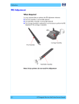
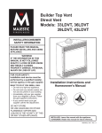
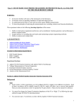
It is very important that you perform the PRS Adjustment whenever:
The Pivot Assembly is removed or replaced.
The Feed Roller Assembly is removed or replaced
The Carriage Assembly is replaced (it is not necessary to perform the PRS
Adjustment if the carriage is reseated).
Carriage Assembly
Pivot Assembly
Feed Roller Assembly
There are 2 different ways to perform the PRS adjustment:
Automatic PRS Adjustment - This is done in repair centers using the PRS
Tool and the Control Application ⇒ Page 5-3.
Manual PRS Adjustment - This is used during on-site repairs or when an
automatic PRS adjustment is not possible ⇒ Page 5-20.
2
hp designjet 90/90r, 120/120nr and 130/130nr printer service manual
PRS Adjustment
Automatic PRS Adjustment
Introduction
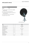
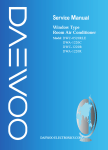
The PRS Adjustment Tool is a measurement tool which is used to measure the
pen to rib space (PRS) within the printer. It is critical that the pen to rib space
is correct and within the given specifications, otherwise the printer will print
with image quality problems.
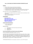
The PRS Adjustment Tool consists of two separate tools:
PRS Pen.
Line Calibration Stand.
PRS Pen
Line Calibration Stand
In addition, the following equipment is also necessary to perform the PRS
Adjustment:
Lucas-Shaevitz MP1000 Display.
Agilent DC Power Supply Unit (Part Number E3640A).
Parallel to Serial Adapter.
PC with 3 serial ports (a PCI Card with 2 serial ports needs to be installed).
Lucas-Shaevitz MP1000 Display
Agilent Power Supply Unit
Parallel to Serial Adapter
hp designjet 90/90r, 120/120nr and 130/130nr printer service manual
3
PRS Adjustment
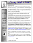
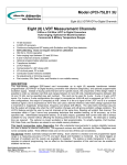
Automatic PRS Adjustment Tool Set-up Connections
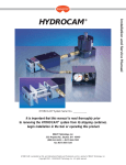
The equipment for the PRS Adjustment Tool needs to be set-up as follows:
Check that the Agilent PSU has the correct
voltage for use in your region before switching
it On. DO NOT connect the PRS Pen to the
PSU until the voltage has been checked and
if necessary, reconfigured. In order to correctly
reconfigure the PSU, refer to the documentation
that accompanied the PSU.
Com 1
Com 2
9
Com 3
1
8
3
2
6
5
7
4
Display Settings
PRS Cable
1 PCS Card 2 Serial Ports.
2 PC-Display Communication Cable.
3 Serial Cable (9 pin female-female connection).
4 Agilent Power Supply Unit (Part Number E3640A).
5 Lucas-Shaevitz MP1000 Display.
6 PRS Pen.
7 Centronics (parallel) Cable (female-male connection).
8 Parallel-Serial Adapter.
9 Serial Cable (standard 9 pin female-male connection).
Power Supply Unit Configuration
Communication Mode - RS-232
Baud Rate - 9600 bps
Parity and Data Bits - None 8 bits
In order to correctly configure the PSU, refer
to the accompanying documentation.
4
hp designjet 90/90r, 120/120nr and 130/130nr printer service manual
PRS Adjustment
Automatic PRS Adjustment Instructions
The PRS Adjustment is split into 2 different processes:
Calibrating the PRS Pen using the Line Calibration Stand.
Checking and, if necessary, adjusting the Pen to Rib space to within
specifications.
Calibrating the PRS Pen
Calibrate the PRS Pen using the Line Calibration Stand as follows:
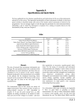
1 Double-click on the controller icon to start the Control Application (Version 1).
2 Click on Config and select Change station or click directly on the
New Plotter box.
3 A "Enter the password to change station" message will appear. You must
enter the following text and then press OK: CHANGEstation.
hp designjet 90/90r, 120/120nr and 130/130nr printer service manual
5
PRS Adjustment
4 A box will appear prompting you to select the Line and Station. For the Line,
select SE and for the Station, select SE50. Click OK.
5 Click on Config and select Identify plotter.
6 Select the Printer Model and type in the Printer Serial Number. Click OK.
C7796A
6
hp designjet 90/90r, 120/120nr and 130/130nr printer service manual
PRS Adjustment
7 Click on Tools, then click on PRS Gauge and then click on Calibration.
8 A message appears on the computer screen with the default values that are
used for the calibration. Check these values against the values on the green
label on the calibration Stand.
9 If the current values displayed on the computer screen are different from the
values on the green label, then you will need to change the values by
selecting Yes on the computer screen. If the values are correct, then select
No and proceed to step 13.
If the values are
different, click Yes
hp designjet 90/90r, 120/120nr and 130/130nr printer service manual
If correct,
click No
7
PRS Adjustment
10 If you selected Yes (to change the values), a series of messages will appear
requesting you to introduce the values for each of the 3 positions. Follow the
messages on the computer screen to introduce the values that appear on the
green label.
11 After you have entered the values for the Calibration stand, you will be
requested to enter the allowed calibration error, which should be 8 microns.
8
hp designjet 90/90r, 120/120nr and 130/130nr printer service manual
PRS Adjustment
12 Once all the values have been entered, a message will appear on the
computer screen with the values that you have just entered. Check these
values against the values on the green label on the Calibration Stand to
make sure they are correct and then select No (or select Yes and re-enter
the values).
If the values are
different, click Yes
If correct,
click No
13 If you select No (meaning the values are correct), a message will appear on
the computer screen requesting you to insert the PRS Tool into the Line
Calibration Stand.
14 Install the PRS Pen inside the Line Calibration Stand. Release the plunger and
lower the clamp into position
15 Place the Line Calibration Stand in the NOM position and click on OK.
hp designjet 90/90r, 120/120nr and 130/130nr printer service manual
9
PRS Adjustment
16 A message will appear on the computer screen requesting you to place the
Line Calibration Stand in the HIGH position. Place the Line Calibration
Stand in the HIGH position and click on OK.
17 A message will appear on the computer screen requesting you to place the
Line Calibration Stand in the LOW position. Place the Line Calibration Stand
in the LOW position and click on OK.
18 If the Calibration fails with an error, the following message will appear and
you must repeat the calibration again.
19 If the Calibration finished correctly, the following message will appear. Click OK.
10
hp designjet 90/90r, 120/120nr and 130/130nr printer service manual
PRS Adjustment
Adjusting the Pen to Rib Space
Do NOT insert the PRS Pen into the Carriage until you are requested
or else you may damage both the PRS Pen and the printer.
Do NOT manually move the Carriage along the print platen while
the PRS Pen is installed or else you may damage the PRS Pen.
Check that the Pen to Rib space is within specifications and, if necessary,
adjust it as follows:
1 Open the Top Cover and the Printhead Access Door and block the Door
Sensor with a piece of paper.
2 Double-click on the Caltrava topLine CSM icon to start the application.
3 Select the Printer Model and type in the Printer Serial Number. Click OK.
4 In the Control Application, click on the START button (make sure first that you
are in Test Station SE50).
Click here
hp designjet 90/90r, 120/120nr and 130/130nr printer service manual
11
PRS Adjustment
5 A message appears that asks you to put the printer in MFG mode. To do
this, while the printer is switched OFF, press both the resume and power
buttons together until the Tool icon appears on the front panel.
Tool Icon
6 Click on OK once the printer is in MFG mode.
7 After a few seconds the Carriage moves to the left and then to the right
several times and then finally comes to a stop above the Service Station and
the following message appears.
8 Open the Access Panel in the Center Cover and pass the PRS Tool through it.
12
hp designjet 90/90r, 120/120nr and 130/130nr printer service manual
PRS Adjustment
9 Open the Carriage Cover and install the PRS Pen into the Magenta Stall.
Make sure that there is enough PRS Pen cable to allow the Carriage to move
along the Scan-Axis of the Printer.
10 Close the Carriage Cover and once you are ready, click OK.
11 The PRS Pen measures the Pen to Rib Space along the Print Platen. Once it
has taken all the measurements, the PRS Pen stops on the left hand side of the
Print Platen and the PRS measurement is displayed on the computer screen.
12 Check the two blocks (one gray and one red) on the computer screen. If the
green bar on the left block is aligned with the green bar on the right block
then the measurement is within specification. Click Accept and the PRS Pen
moves to the right hand side of the Print Platen. Again, check the two blocks
on the computer screen. If the two green bars are aligned then the
measurement is within specification. Click Accept to continue.
hp designjet 90/90r, 120/120nr and 130/130nr printer service manual
13
PRS Adjustment
13 If the green bar on the left block is below or above the green bar on the
right block, then the measurement is out of specification and the Pen to Rib
Space needs to be adjusted.
14 Adjust the Pen to Rib Space as follows:
a Using a very long torx screwdriver (T-8) either tighten or loosen the Pivot
Assembly screw. Tightening or loosening the screw will adjust the Pen to
Rib Space until the green bar on the left block is aligned with the green bar
on the right block. If the current position is LOW, then tighten the screw
slightly, if the current position is HIGH, then loosen the screw slightly.
LOW = Tighten Screw
HIGH = Loosen Screw
Tighten or Loosen the screw using a Torx screwdriver
until the two green bars are aligned
Pass the Screwdriver
through this hole in
the Center Cover
b Once the two green bars are aligned, click Accept and the PRS Pen will
move to the right hand side of the printer.
14
hp designjet 90/90r, 120/120nr and 130/130nr printer service manual
PRS Adjustment
c Using a very long torx screwdriver (T-8) either tighten or loosen the Pivot
Assembly screw. Tightening or loosening the screw will adjust the Pen to
Rib Space until the green bar on the left block is aligned with the green bar
on the right block. If the current position is LOW, then tighten the screw
slightly, if the current position is HIGH, then loosen the screw slightly.
LOW = Tighten Screw
HIGH = Loosen Screw
Tighten or Loosen the screw using a Torx screwdriver
until the two green bars are aligned
Pass the Screwdriver
through this hole in
the Center Cover
d Once the two green bars are aligned, click Accept.
15 The PRS Pen measures the Pen to Rib Space along the Print Platen again.
Once it has taken all the measurements, the PRS Pen moves to the Service
Station and the following message is displayed on the computer screen.
hp designjet 90/90r, 120/120nr and 130/130nr printer service manual
15
PRS Adjustment
16 Open the Carriage Cover and remove the PRS Pen from the Magenta Stall.
17 Close the Carriage Cover and then click OK.
18 If the calibration was performed correctly and the Pen to Rib Space is within
specification, then the following message is displayed on the computer screen.
19 If the calibration was performed incorrectly or the Pen to Rib Space is out of
specification, then the following message is displayed on the computer screen.
Click on Retry if you want to retry the Calibration.
16
hp designjet 90/90r, 120/120nr and 130/130nr printer service manual
PRS Adjustment
20 If during the PRS Calibration an error message appears, refer to the
following table in order to troubleshoot it:
TG_SE_PRS_Calibration
Test name
Error Message
Troubleshooting
HCOM
NONE
CIMation failed to
communicate with the
Printer.
Repeat the test after
checking that ALL the cables
are correctly connected.
Check User
Mode
Unit booted in 0 mode
while expected 1
Printer initialized in a
different mode than the
expected.
Initialize the Printer in the
correct mode (MFG) and
click on "Retry".
{C} PRS
Adjustment
(Top)
1. Target PRS values
for adjustment are too
small. Potential
Carriage Crash.
Pivot might be assembled
too high.
Check that the Pivot position
is away from the PRS pen
crash.
2. Potential Carriage
bushing missing.
Based on the calculation
Check that the carriage
the possibility of the
busing is present and then
Carriage Bushing missing. click "OK" to proceed with
adjustment. If bushing is
NOT present, click "NO" to
the failed test
3. Error adjusting PRS
at position.
3. Printer Out of Spec.
Repeat the entire test one
more time.
PRS Adjustment Tool Maintenance
The maintenance schedule for the PRS Tool should include the actions listed
below. As experience with the PRS Tool increases, the maintenance schedule
should be adjusted according to the actual wear of the PRS Tool.
Daily Maintenance
Inspect the Calibration Stand for dirt or debris, and clean as necessary.
Ensure that the probe tip moves freely when using the solenoid button.
Weekly Maintenance
Inspect tools for worn, damaged or missing parts, and replace as
necessary.
Inspect the latches and springs on the Calibration Stand.
Inspect the PRS Pen cable and verify that there are no exposed
conductors on the cable assembly.
hp designjet 90/90r, 120/120nr and 130/130nr printer service manual
17
PRS Adjustment
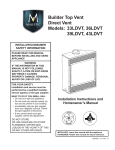
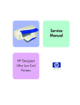
Automatic PRS Adjustment Troubleshooting
The following table contains a list of common problems you may encounter
while using the PRS Adjustment Tool and the possible causes and solutions:
Cable
Solenoid
Cover Plate
LDVT
Front Plate
Lifter
Probe Tip
Problem
Possible Cause
Solution
Measurement
numbers are out of
specification.
PRS Pen cable is in a position that
causes the Carriage to lift or is
affecting the position of the PRS Pen.
Check that the PRS Pen cable is NOT
pulling the PRS Pen out of position.
Probe tip is not on a rib.
Position the Carriage so that the
probe tip is sitting flat on a rib.
Probe tip is stuck against a pivot
rib.
Check that the probe tip is not stuck
against the edge of a rib. Move the
Carriage slightly in order to free the
probe tip.
The Solenoid is not plugged in.
Make sure that the solenoid is
energized when the button is
pressed.
The lifter is binding inside the PRS
Tool.
Make sure that there is adequate
clearance around the wire lifter and
that it is not hanging on any part of
the PRS Pen.
Probe Tip will not
lower.
The lifter might be binding inside
the PRS Tool preventing the probe
tip from full extension.
Make sure that there is adequate
clearance around the wire lifter and
that it is not hanging on any part of
the PRS Pen.
Measurement
values are too high
when checking in a
Calibration Stand.
The Calibration Stand may have
debris or it may be preventing the
PRS Pen from sitting correctly in it’s
datum.
Check that the PRS Pen cable is NOT
pulling the Carriage out of position.
There should be no gap between the
Carriage and the rail.
Probe tip will not
raise.
18
hp designjet 90/90r, 120/120nr and 130/130nr printer service manual
PRS Adjustment
Problem
Communication
error with the
Computer.
Numbers from the
Calibration Stand
are out of
specification.
PRS Pen numbers
are low.
Possible Cause
Solution
The MP1000 Display rebooted.
Make sure that the MP1000 Display
is ON and is in run mode, then
restart the communications link.
The MP1000 Display was
calibrated while still connected to
the computer.
Normally, if the MP1000 Display
controls are used while attached to
the computer, it will cause a break in
the communication link. Try to reestablish the communication link
after the MP1000 Display is setup
and in run mode.
Probe Tip was not released onto
the reference datum using the
Solenoid switch.
Always use the Solenoid switch to
raise and lower the Probe Tip. This
will ensure that the Probe Tip drops
straight down and will get stuck
against the reference datum.
Datum surfaces on the Calibration
Stand are worn.
Check the Calibration using the
Calibration-Master Stand. If the
values are within specifications, then
the Calibration Stand should be sent
to the Metrology Lab to verify that the
datum surfaces are correct.
The Calibration Stand or the PRS
Pen may have debris which is
preventing the PRS Pen from either
sitting correctly in it’s datum or it
might be affecting the reference
surface.
Make sure that ALL datums on both
the PRS Pen and the Calibration
Stand are clean and free from debris.
Also check that there is nothing else
preventing the PRS Pen from sitting
correctly on the Pen Datums in the
Calibration Stand.
The PRS Tools need to be
recalibrated.
Check the Calibration using the
Calibration-Master Stand. If the
values NOT within the specifications,
recalibrate the PRS Tool using the
Calibration-Master Stand.
Wires inside the PRS Pen body are
preventing the probe tip to move.
Remove the cover plate of the PRS
Pen and make sure that the wires are
not preventing the probe tip to move.
Probe tip is not locked tight onto
the core.
Remove the cover plate of the PRS,
remove the LVDT and inspect the
probe tip and core. Use LocktiteTM
(preferably #242 which is
removable) to secure the probe tip
onto the core. This will help to ensure
that the probe tip does not back itself
out over a period of time.
hp designjet 90/90r, 120/120nr and 130/130nr printer service manual
19
PRS Adjustment
Manual PRS Adjustment
The purpose of the Manual PRS Adjustment is to adjust the distance between
the Carriage Assembly and the Pivot Assembly. This adjustment is necessary
in order to prevent problems like Printhead crashes.
Perform the Manual PRS Adjustment as follows:
The Manual PRS Adjustment should be carried out using the
Carriage Height Tool.
Carriage Height Tool
During the Manual PRS Adjustment procedure the Carriage
Assembly has to be moved along the length of the printer. Make
sure that the Carriage Assembly is only ever moved by pulling
the belt and never by direct contact with the Carriage itself.
Correct: move using the belt.
20
Incorrect: never move using Carriage Assembly.
hp designjet 90/90r, 120/120nr and 130/130nr printer service manual
PRS Adjustment
1 Turn On the Printer and open the Printhead Access Door.
Make sure that you turn ON the Printer, otherwise you will
NOT be able to open the Carriage Cover.
2 Open the Carriage Cover and install the Carriage Height Tool into the
Magenta Stall - Make sure ALL the other printheads are already removed
from the Carriage Assembly.
3 Close the Carriage Cover and switch OFF the Printer.
Make sure that you turn OFF the Printer, otherwise you will
NOT be able to manually move the Carriage Assembly.
hp designjet 90/90r, 120/120nr and 130/130nr printer service manual
21
PRS Adjustment
4 Move the Carriage Assembly to the left hand side of the Printer (to the
position shown).
5 Using the belt, move the Carriage Assembly backwards and forwards over
the Pivot Assembly (but staying on the left hand side of the printer), carefully
listening for a scraping sound.
22
hp designjet 90/90r, 120/120nr and 130/130nr printer service manual
PRS Adjustment
6 If you hear a scraping sound, that means that the Pivot Assembly is too high
and needs to be lowered slightly. Lower the Pivot Assembly slightly by
turning the T-8 screw 1/8th of a turn clockwise and then check for a
scraping sound again as shown previously in step 5.
Cross-Section - Lowering the Pivot Assembly
hp designjet 90/90r, 120/120nr and 130/130nr printer service manual
23
PRS Adjustment
7 If you don’t hear a scraping sound, that means that the Pivot Assembly is too
low and needs to be raised slightly. Raise the Pivot Assembly slightly by
turning the T-8 screw1/8th of a turn anti-clockwise and then check for a
scraping sound again as shown previously in step 5.
Cross-Section - Raising the Pivot Assembly
24
hp designjet 90/90r, 120/120nr and 130/130nr printer service manual
PRS Adjustment
8 Repeat steps 5 to 7 until you reach a point where you will hear the scraping
sound and by turning the screw just 1/8th of a turn clockwise, the scraping
sound will disappear.
9 Move the Carriage Assembly to the right hand side of the Printer (to the
position shown).
10 Using the belt, move the Carriage Assembly backwards and forwards over
the Pivot Assembly (but staying on the right hand side of the printer),
carefully listening for a scraping sound.
hp designjet 90/90r, 120/120nr and 130/130nr printer service manual
25
PRS Adjustment
11 If you hear a scraping sound, that means that the Pivot Assembly is too high
and needs to be lowered slightly. Lower the Pivot Assembly slightly by
turning the T-8 screw 1/8th of a turn clockwise and then check for a
scraping sound again as shown previously in step 10.
Cross-Section - Lowering the Pivot Assembly
26
hp designjet 90/90r, 120/120nr and 130/130nr printer service manual
PRS Adjustment
12 If you don’t hear a scraping sound, that means that the Pivot Assembly is too
low and needs to be raised slightly. Raise the Pivot Assembly slightly by
turning the T-8 screw1/8th of a turn anti-clockwise and then check for a
scraping sound again as shown previously in step 10.
Cross-Section - Raising the Pivot Assembly
hp designjet 90/90r, 120/120nr and 130/130nr printer service manual
27
PRS Adjustment
13 Repeat steps 10 to 12 until you reach a point where you will hear the
scraping sound and by turning the screw just 1/8th of a turn clockwise, the
scraping sound will disappear.
14 Move the Carriage Assembly along the length of the Printer, listening
carefully for the scraping sound.
15 If you don’t hear the scraping sound, then the PRS Adjustment is correct, go
to step 17.
28
hp designjet 90/90r, 120/120nr and 130/130nr printer service manual
PRS Adjustment
16 If you hear the scraping sound, then you will need to lower the Pivot
Assembly slightly by turning the T-8 screw 1/8th of a turn clockwise on both
the left and right hand side of the Pivot Assembly. Check for a scraping
sound again as shown previously in step 14.
17 Remove the Carriage Height Tool.
hp designjet 90/90r, 120/120nr and 130/130nr printer service manual
29
PRS Adjustment
30
hp designjet 90/90r, 120/120nr and 130/130nr printer service manual