1
L-Series Libraries
L700/L1400 Library Encryption Hardware
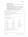
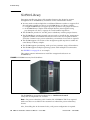
The L700 and L1400 libraries have an internal, 13-unit, rack “area” accessible from
behind the right front door or the left rear door of the library. The encryption hardware
can be installed from either the front or the rear; however, a rear installation offers
more space for cabling.
Rack area requirements:
■ Total maximum weight in this location cannot exceed 136 kg (300 lb).
■ Power cable space is provided in the cutout area of the rear door.
■ Ventilation openings in the rear of the cabinet must have at least 100 mm (4 in.)
clearance for proper air flow.
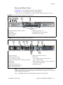
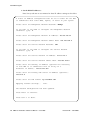
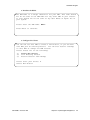
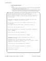
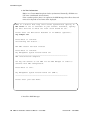
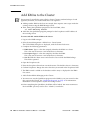
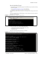
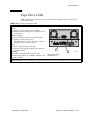
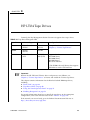
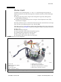
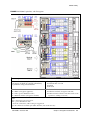
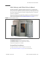
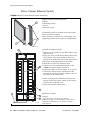
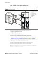
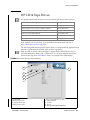
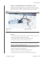
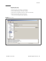
FIGURE 5-11 L-Series Libraries
Callouts:
1. KMAs (2)
2. Ethernet switch
3. PDU
4. Ethernet to
Drive cables
1
2
3
5
KMA
KMA
4
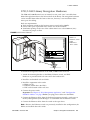
To install the encryption hardware in the L700/L1400 internal rack area:
1. Attach the mounting brackets to the KMAs, Ethernet switch, and PDU.
Hardware is provided with each unit and in the hardware kit.
2. Install the rack module rails and slides.
3. Install the equipment in this order:
■
KMAs on top.
■
Ethernet switch above the PDUs.
■
PDU on the bottom of the rack area.
4. Connect the power cords.
Important: See Chapter 2, “Key Management Appliances” and “Configure the
ELOM IP Address” on page 8 before you plug power cables into the KMAs.
5. Connect the Ethernet cables from the dedicated customer network—with access to
the Key Management System Manager—to each KMA and the Ethernet switch.
6. Connect the Ethernet cables from the switch to the tape drives.
Note – Because the Ethernet switch was previously installed in this configuration, the
KMAs are installed above the switch.
316194903 • Revision: BA
Chapter 5 Encryption Hardware Kits
69