1
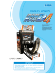
www.seuservice.com
1ST PRINTING JUNE ‘04
Software
Conversion Kit
Kit Installation Instructions & Service Manual
1 - 2 PLAYER GAME
SEGA AMUSEMENTS USA, INC.
MANUAL NO. 999-2080
GAME CODE: TOSK
VISIT OUR WEBSITE!
BEFORE USING THE PRODUCT, BE SURE TO READ THE FOLLOWING:
To maintain the safety:
To ensure the safe usage of the product, be sure to read the following before using the product. The
following instructions are intended for the users, operators and the personnel in charge of the operation of the product. After carefully reading and sufficiently understanding the warning displays and
cautions, handle the product appropriately. Be sure to keep this manual nearby the product or elsewhere convenient for referring to it when necessary.
Herein, explanations which require special attention are enclosed with dual lines. Depending on the
potentially hazardous degrees, the terms of WARNING, CAUTION, etc. are used. Be sure to understand the contents of the displays before reading the text.
WARNING!
Indicates that mishandling the product by disregarding this warning
will cause a potentially hazardous
situation which can result in death
or serious injury.
CAUTION!
Indicates that mishandling the product
by disregarding this caution will cause
a slight hazardous situation which can
result in personal injury and or material
damage.
For the safe usage of the product, the following pictographs are used:
Indicates “HANDLE WITH CARE.” In order to protect the human body an equipment,
this display is attached to places where the Owner’s Manual and or Service Manual should
be referred to.
Perform work in accordance with the instructions herein stated.
Instructions for work are explained by paying attention to the aspect of accident prevention. Failing to
perform work as per the instructions can cause accidents. In the case where only those who have technical expertise should perform the work to avoid hazardous situation, the instructions herein state that the
serviceman should perform such work.
Be sure to turn off power before working on the machine.
To prevent electric shock, be sure to turn off power before starting the work in which the worker touches
the interior of the product. If the work is to be performed in the power-on status, the Instruction Manual
herein always states to that effect.
Be sure to ground the Earth Terminal (this, however, is not required in the case where a power cord
with earth is used).
This product is equipped with the Earth Terminal. When installing the product, Connect the Earth Terminal to the “accurately grounded indoor earth terminal” by using an earth wire. Unless the product is
grounded appropriately, the user can be subject to electric shock. After performing repair, etc. for the
Control equipment, ensure that the Earth Wire is firmly connected to the Control equipment.
Ensure that the Power Supply used is equipped with an Earth Leakage Breaker.
This product does not incorporate the Earth Leakage Breaker. Using a power supply which is not
equipped with the Earth Leakage Breaker can cause a fire when earth leakage occurs.
Be sure to use fuses which meet the specified rating. (only for the machines which use fuses).
Using fuses exceeding the specified rating can cause a fire and electric shock.
Specification changes (removal of equipment, conversion and addition) not designated by SEGA
are not allowed.
The parts of the product include warning labels for safety, covers for personal protection, etc. It is
very hazardous to operate the product by removing parts and or modifying the circuits. Should doors,
lids and protective parts be damaged or lost, refrain from operating the product, and contact where the
product was purchased from or the office herein stated. SEGA shall not be held responsible for any
accidents, compensation for damage to a third party, resulting from the specifications not designated by
SEGA.
Ensure that the product meets the requirements of appropriate Electrical Specifications.
Before installing the product, check for Electrical Specifications. SEGA products have a nameplate
on which Electrical Specifications are described. Ensure that the product is compatible with the power
supply voltage and frequency requirements of the location. Using any Electrical Specifications different
from the designated Specifications can cause a fire and electric shock.
Install and operate the product in places where appropriate lighting is available, allowing warning
labels to be clearly read.
To ensure safety for the customers, labels and printed instructions describing potentially hazardous situation are applied to places where accidents can be caused. Ensure that where the product is operated
has sufficient lighting allowing the warnings to be read. If any label is peeled off, apply it again immediately. Please place an order with where the product was purchased from or the office herein stated.
When handling the Monitor, be very careful. (Applies only to the product w/monitor.)
Some of the monitor (TV) parts are subject to high tension voltage. Even after running off power, some
portions are still subject to high tension voltage sometimes. Monitor repair and replacement should be
performed only be those technical personnel who have knowledge of electricity and technical expertise.
Be sure to adjust the monitor (projector) properly. (Applies only to the product w/monitor.)
Do not operate the product leaving on-screen flickering or blurring as it is. Using the product with the
monitor not properly adjusted may cause dizziness or a headache to an operator, a player, or the customers.
When transporting or reselling this product, be sure to attach this manual to the product.
In the case where commercially available monitors and printers are used in this product, only the contents relating to this product are explained herein. Some commercially available equipment has functions and reactions not stated in this manual. Read this manual together with the specific Instruction
Manual of such equipment.
• Descriptions herein contained may be subject to improvement changes without notice.
• The contents described herein are fully prepared with due care. However, should any question arise or
errors be found, please contact SEGA.
INSPECTIONS IMMEDIATELY AFTER TRANSPORTING THE PRODUCT TO THE LOCATION.
Normally, at the time of shipment, SEGA products are in a status allowing for usage immediately after
transporting to the location. Nevertheless, an irregular situation may occur during transportation. Before
turning on power, check the following points to ensure that the product has been transported in a satisfactory status.
Are there any dented portions or defects (cuts, etc.) on the external surfaces of the cabinet?
Are Casters and Adjusters, damaged?
Do the power supply voltage and frequency requirements meet with those of the location?
Are all wiring connectors correctly and securely connected? Unless connected in the correct direction,
connector connections can not be made accurately. Do not insert connectors forcibly.
Do power cords have cuts and dents?
Do the fuses used meet specified rating? Is the Circuit Protector in an energized status?
Are all accessories available?
Can all Doors and Lids be opened with the Accessory keys? Can Doors and Lids be firmly closed?
Initial “D” Ver. 3
Naomi 2 Software
Kit Contains List
Before begining installation, check to make sure the kit contains the following parts.
Details of the parts are given below.
Part #
Desc
Qty
999-2080
610-0624-0033
Upgrade Manual (this document)
GD Software Kit TOS ENG
1
1
442-00148-B
601-11358-01
421-8075-81
421-11409-12
421-7988-91
Sticker 840-0148B (for shield case)
Card Package TOS (Initial D3) ENG
JASRAC Sticker TOS
Sticker JASRAC V TOS
Sticker Serial Number
1
1
1
1
1
999-2092
999-2087
999-2088
999-2089
999-2086
999-2084
999-2082
999-2083
999-2090
Instruction Card TOS
Play Instructions TOS
Monitor Side Left TOS
Monitor Side Right TOS
POP Art TOS
Decal Seat Back Lower TOSK
Decal Seat Back Mid TOSK
Decal Seat Back Upper TOSK
Decal Base Box TOS
1
1
1
1
1
1
1
1
2
1
www.seuservice.com
DESIGNED RELATED PARTS
999-2092
Instruction Card TOS
➔
➔
999-2088
Monitor Side Left TOS
➔
➔
www.seuservice.com
999-2087
Play Instructions TOS
2
999-2089
Monitor Side Right TOS
999-2086
POP Art TOS
➔
999-2084
Decal Seat Back Lower TOSK
999-2082
Decal Seat Back Mid TOSK
➔
999-2083
Decal Seat Back Upper TOSK
➔
➔
3
➔
999-2090
Decal Base Box TOS
www.seuservice.com
UPGRADING
Perform all operations with the power switch turned off. Failure to do so may
result in electrical shock and/or short circuiting. In addition, working with the
power turned on may result in fingers becoming caught and injured in the spinning
fan motor.
REPLACING THE KEY CHIP AND GD-ROM
Follow the steps listed below to replace the Key Chip and GD-ROM with the ones included in
this kit
• Turn off the power.
• Remove the truss screws (one each) from the left and right sides of the base lid R.
• Unlock the lid using the master key.
• Turn the lock handle on the base lid R to release the latch.
• Tilt and let the seat rest on its backrest. Taking care not to damage the seat, gently lower until
the backrest rests on the floor. If the floor surface is hard, spread a cloth or towel on the floor to
protect the surface of the sheet from scratching.
LOCK HANDLE
DROP CLOTH TO
PREVENT DAMAGE
UNLOCK
TRUSS SCREW (2), black _
M5×12
FIG. 2. 1
www.seuservice.com
4
Replacing the Key Chip
● The Key Chip is a precision part. Exposure to heat or static electricity or
collision with another object may damage it. Be sure to handle it with care.
● The Key Chip must be used in conjunction with the game GD-ROM disc
contained in the same package.
● Using the cabinet's NAOMI Network System Service Manual as reference, remove the existing
Key Chip from the game board and replace it with the Key Chip included in the kit.
● Affix the sticker (442-0148B) contained in the kit to the DIMM board case in the position
indicated by the diagram.
KEY CHIP
STICKER(442-00148B)
Sticker Position
FIG. 2. 1. 1
Replacing the GD-ROM
● Handle the surface of the GD-ROM disc and the reader lens of the GD-ROM
drive with care to protect them from dirt and dust.
● Do not use the GD-ROM disc if the surface has been scratched. Using a
scratched disc may cause the GD-ROM drive to malfunction.
● Be sure to place the GD-ROM disc into the GD-ROM drive with the label
side facing up.
Using the cabinet's NAOMI Network System Service Manual as reference, remove the existing
GD-ROM disc from the GD-ROM drive and replace it with the disc included in the kit.
5
www.seuservice.com
CONFIRMING THE UPGRADE
Using the "Explanation of Test and Data Display" section of the instruction manual contained in
the kit as reference, check to make sure that the upgrade has been performed correctly and that
all systems are working properly. Be sure to adjust the monitor to correct for any flickering or
distortion before operating the product. Refer to the "Monitor" section of the instruction manual
included in the kit for details.
www.seuservice.com
6
Game Overview
The game is a car racing game with three different game modes: "Legend of the Street", "Time
Attack" and "The Bunta Challenge". By connecting two units, you can also enjoy "Network
Battle Game" play. The card system allows players to store information such as the car, wins/
loss records and car tune-up status on a special card.
Legend of the Street
●Game Content & Rules
Battle rival characters man to man on 9 different courses. Each checkpoint you pass adds time to
the overall time limit. The first one across the finish line with the allotted time wins. If you run
out of time or cross the finish line second, you lose.
Once you've defeated all 28 rival characters, you'll get a chance to race against a hidden rival
character I and a hidden rival character II (final battle/race). Defeat them and you'll race for the
title of street legend against the last hidden rival character (special battle/race). Only when the
title is yours will you get to see the ending.
●INITIAL D CARD
Purchasing a card when you start the game creates your car.
The card can store all the data for one car. Information on the card
includes the player name, car, tune-up status, names of defeated rival
characters, times from Time Attack mode, Network Game records,
passwords from Time Attack mode and more.
On the Card Screen, the player's name, car name, cleared areas, Key
and Speed Demon Level are displayed. The Key is necessary when
recording results on the Net Rankings.
Speed Demon Level stars (★) increase as various conditions are
cleared.
(Player's name)
KEY
***
(Car name)
(Cleared areas)
★
(Speed Demon Level)
●Car Tune-Ups
Depending on how well you do, points are added to your card when you use it to play in
"Legend of the Street", "Time Attack", "The Bunta Challenge" and "Network Battle Race"
modes. When you've accumulated enough points, you are given the option of using those points
to do tune-ups on your car to increase performance.
7
www.seuservice.com
● Vehicle Selection Screen:
This screen isn't displayed if
you've already purchased a
card.
● Transmission Selection Screen:
This screen isn't displayed if
you've already purchased a
card.
● Parts Course Selection Screen:
If you're purchasing a card,
select one of the Parts courses.
These parts are then attached to
your car when you accumulate
enough points.
www.seuservice.com
8
● Vehicle Selection Screen:
This screen isn't displayed if
you've already purchased a
card.
● Transmission Selection Screen:
This screen isn't displayed if
you've already purchased a
card.
● Parts Course Selection Screen:
If you're purchasing a card,
select one of the Parts courses.
These parts are then attached to
your car when you accumulate
enough points.
9
www.seuservice.com
● Name Entry Screen:
If you're purchasing a card,
enter your name (driver's name)
at the player name input screen.
● Mode Select Screen:
Select "Legend of the Street" at
the Mode Selection Screen.
● Course and Rival Character Selection Screens
www.seuservice.com
10
● Rival Character Scenes
● Battle (Race)
● Results Screen
11
www.seuservice.com
● Tune Up Screen:
Use your card to play and
accumulate points you can put
towards performance enhancing
tune-ups.
● Continue Screen:
Choose to continue or quit
after rival character scenes. If
you select "YES", nothing is
recorded to the card and you
can continue playing. If you
select "NO", your game data is
stored on your card and your
game ends.
www.seuservice.com
12
Time Attack
● Game Content & Rules
This is a race against time. The goal is to cross the finish line as quickly as you can.
Direction, Time of Day and Weather can be selected for each of the nine courses - note that
Happogahara and Akina (Snow) can only be set to Night.
Each checkpoint you pass adds time to the overall time limit. When you cross the finish line, a
password is displayed. (The password is not displayed when you don't use the card.)
You may use this password to participate in the online Internet rankings.
In order to register the password, you must have played the game with a card and you'll need to
enter the 3 digit number or KEY printed on the front of the card.
Your times, when recorded with the Card (tuned car), are displayed in the ranking. The way to
accumulate points is to play with a card.
The Bunta Challenge
● Game Content & Rules
Race head-to-head against a single rival, Fujiwara Bunta, on eight different courses: Myogi,
Usui, Akagi, Akina (Snow on Level 11), Happogahara, Shomaru and Tsuchisaka.
For each course, only Dry or Night conditions may be selected.
A Card with saved points is necessary to play.
Player must finish ahead within the time limit to win.
Finishing behind or over the time limit means the player loses.
Beating Bunta earns points and increases the Bunta Level for that course by one.
The Bunta Level indicates Bunta's strength; the higher the level the stronger he becomes.
Losing reduces the player's points total.
Network Battle Race
● Game Content & Rules
Two vehicles race for victory.
When either car passes a checkpoint, remaining race time will be increased.
The winner is the car that crosses the finish line first or is occupying first place when time runs
out.
A car built on the Card (tuned car) may also be used.
When racing with a tuned car, results will be saved on the Card.
Challengers may challenge at any point during the champion side race.
Cards may not be purchased during a Network Battle Race.
13
www.seuservice.com
Before the Race
[Champion Side]
● Battle Entry Challenge Request
Screen
When a challenge occurs before
the start of the race (during
selection phase):
If the challenge occurs before
the mode selection phase (during
Car Selection etc), the Network
Battle Race Information Screen
is displayed directly before the
selection phase.
If the challenge occurs after
the selection phase, selection
is interrupted and the Network
Battle Race Information Screen is
displayed.
When a challenge occurs during
the race:
The race is interrupted and the
Network Battle Race Information
Screen is displayed.
● Network Battle Race Information
Screen
The challenger selects the course
while the champion waits at the
Network Battle Race Information
Screen.
www.seuservice.com
14
[Challenger Side]
● Network Battle Race Select Screen
This screen asks if a new player
wishes to enter a Battle Race. It
only appears when a new player
first inserts coins and the current
player has opted to accept Battle
Race challengers.
● Card Entry Screen
When a Battle Race is established,
the Card Entry Screen appears.
A Battle can be raced even without
a Card.
If there is no Card, the game
proceeds to the Car Selection and
Transmission Selection Screens.
The Course Selection Screen then
appears. The challenger selects the
course.
After the Race
● Results Screen
After a battle, the Results Screen
appears.
Depending on the results, the
Battle Level will change.
15
www.seuservice.com
● Continue Screen
The winning player will receive
victory points and will be allowed
to continue play.
The losing player will go to the
Continue Screen.
When the number of victories
exceeds the set limit
When a player's total number of
victories exceeds the set limit,
the player will be taken to the
Continue Screen even if they win.
(See Section "10-3 F".)
Configuration
When a Card is inserted, a number
of options may be set.
Press the View Change Button at
the Card Data Confirmation Screen
to go to the Configuration screen.
When displaying the configuration
Screen, you can select the item by
the Shift Lever. After selecting the
item, press the Start Button and
change the setting by the Steering
Wheel. After changing the setting,
press the Start Button again to be
settled the new settings.
● BGM
Set race background music options
ON: Play BGM as normal (Default Setting).
OFF: Turn BGM off.
FIX: Play the melody selected at Song Selection. Will play the same BGM until changed.
● NAVIGATION WINDOW
Set options for the Navigation Display that appears at the lower left of the Race Screen.
ON: Show navigation display (Default setting).
OFF: Do not show navigation display.
PAPER CUP: A paper cup full of water appears on the navigation display.
● STEERING
Set steering wheel stiffness.
1 to 9: 1 is the loosest. Stiffness increases up to a maximum setting of 9.
(Default Setting is 5)
www.seuservice.com
16
● TIME DISPLAY
Set the Time Display on the Race Screen.
NORMAL: Standard time display. (Default setting)
SIMPLE: Simplified time display.
● FORCED QUIT
Force end of game during Legend of the Streets and Time Attack play.
OFF: Disable force quit (Default setting)
ON: Enable force quit. Press the Start and Change View Buttons simultaneously to end
game.
Game Over
With “Legend of the Street”, “Time Attack” and “Network Battle Race” play, the Continue
Screen appears after each race.
If you choose not to continue, the game ends.
Transferring Old Card Data
Card data from the previous versions, "Initial D" and "Initial D Ver. 2"may be transferred for use
with "Initial D Ver. 3". Not all player data will be transferred to the new Card.
● Transferable Data:
Points, car model, player name, customization options, Auto/
Manual transmission setting, number of plays till next inspection
(the number of plays remaining on the Card, plus 50, max. 127).
● Non-transferable Data: Tune-up (Tune-up status is returned to default, but transferred
points may be used to re-tune the car), times, race results, Legend
of the Street status, Key and Speed Demon Level, Network Battle
Level, Bunta Level.
1. The player inserts coins to start.
Player inserts Card at the Card Entry Screen.
17
www.seuservice.com
2. Player inserts credits at the Transfer Card Data Screen.
3. The old Card will be ejected. This Card can no longer be used.
4. When the "Card Data Transferred" message appears, the game will restart.
The new Card is for exclusive use with the Initial D Ver. 3, and cannot be used with the
previous versions, Initial D and Initial D Ver. 2.
Limit on Card Use
Each Card can be used for up to fifty plays, until Car Inspection time is reached. Continued
game play after each race is not counted as part of the 50 game limit. Cards may be renewed by
transferring data to a new Card (stored points will not be lost). However, if you do not renew
your card at the Car Inspection, you will not longer be able to play using the data stored on your
card.
www.seuservice.com
18
Car Selections
TOYOTA
TRUENO GT-APEX [AE86]
LEVIN GT-APEX [AE86]
LEVIN SR [AE85]
MR2 G-Limited [SW20]
MR-S S EDITION [ZZW30]
ALTEZZA RS-200 [SXE10]
CELICA GT-FOUR [ST205]
MAZDA
RX-7 Type R [FD3S]
RX-7 SPIRIT R Type A [FD3S]
RX-7∞III [FC3S]
RX-8 Type S [SE3P]
ROADSTER S Special [NA6CE]
ROADSTER RS [NB8C]
SUBARU
IMPREZA WRX STi Version VI [GC8]
IMPREZA WRX STi [GDB]
IMPREZA WRX type R STi Version V [GC8]
NISSAN
SKYLINE GT-R V-spec II [BNR32]
SKYLINE GT-R V-spec II [BNR34]
SKYLINE 25GT TURBO [ER34]
SILVIA K's [S13]
SILVIA Q's [S14]
SILVIA K's AERO [S14]
SILVIA spec-R [S15]
180SX TYPE X [RPS13]
SILEIGHTY [RPS13]
SUZUKI
CAPPUCCINO [EA11R]
HONDA
CIVIC SiR II [EG6]
CIVIC TYPE R [EK9]
INTEGRA TYPE R [DC2]
S2000 [AP1]
MITSUBISHI
LANCER GSR EVOLUTION III [CE9A]
LANCER RS EVOLUTION IV [CN9A]
LANCER RS EVOLUTION V [CP9A]
LANCER GSR EVOLUTION VI T.M.EDITION [CP9A]
LANCER GSR EVOLUTION VII [CT9A]
Race Course
● Easy
● Myogi, Circular Course/3 laps, Clockwise & Counter-clockwise, Day & Night,
Fine & Rainy
● Normal
● Usui, Circular Course/2 laps, Clockwise & Counter-clockwise, Day & Night,
Fine & Rainy
● Hard
● Akagi, Single road, Uphill & Downhill, Day & Night, Fine & Rainy
● Hard
● Akina, Single road, Uphill & Downhill, Day & Night, Fine & Rainy
● Expert
● Irohazaka, Single road, Downhill/Reverse, Day & Night, Fine & Rainy
● Expert
● Akina (Snow), Single road, Uphill & Downhill, Night
● Expert
● Happogahara, Single road, Outbound & Inbound, Night, Fine & Rainy
● Expert
● Shomaru, Single road, Outbound & Inbound, Day & Night, Fine & Rainy
● Expert
● Tsuchisaka, Single road, Outbound & Inbound, Day & Night, Fine & Rainy
19
www.seuservice.com
"Legend of the Street" Rival Characters
(EASY - Myogi)
IGGY
KENJI
SHINGO
LEVIN SR [AE85]
180SX TYPE X [RPS13]
CIVIC SiR II [EG6]
(NORMAL - Usui)
TORU
KAWAI
MAYA&SIMONE
ROADSTER S Special [NA6CE]
SKYLINE 25GT TURBO [ER34]
SILEIGHTY [RPS13]
(HARD - Akagi)
TWO GUYS FROM TOKYO SILVIA spec-R [S15]
DANNY
SILVIA Q's [S14]
K. T.
RX-7 Type R [FD3S]
(HARD - Akina)
COLE
ZACK
KYLE
RY
TAK
BUNTA
SILVIA K's [S13]
SKYLINE GT-R V-spec II [BNR32]
LANCER GSR EVOLUTION III [CE9A]
RX-7 ∞III [FC3S]
TRUENO GT-APEX [AE86]
IMPREZA WRX type R STi Version V [GC8]
(EXPERT - Irohazaka)
HAWK
KYLE
CAINE
LANCER RS EVOLUTION IV [CN9A]
LANCER GSR EVOLUTION III [CE9A]
MR2 G-Limited [SW20]
(EXPERT - Akina Snow)
MIKI
CELICA GT-FOUR [ST205]
(EXPERT - Happogahara)
DICE
SMILEY
TOUCH
CIVIC TYPE R [EK9]
INTEGRA TYPE R [DC2]
CIVIC TYPE R [EK9]
(EXPERT - Shomaru)
NOBU
SID
AKI
ALTEZZA RS-200 [SXE10]
CAPPUCCINO [EA11R]
LEVIN GT-APEX [AE86]
(EXPERT - Tsuchisaka)
KYLIE
RY
Man in Evo V
Man in Evo VI
K. T.
TAK
RX-7 Type R [FD3S]
RX-7 ∞III [FC3S]
LANCER RS EVOLUTION V [CP9A]
LANCER GSR EVOLUTION VI T.M.EDITION [CP9A]
RX-7 Type R [FD3S]
TRUENO GT-APEX [AE86]
www.seuservice.com
20
EXPLANATION OF TEST AND DATA DISPLAY
By operating the switch unit, periodically perform the tests and data check. When installing the
machine initially or collecting cash, or when the machine does not function correctly, perform
checking in accordance with the explanations given in this section.
The following shows tests and modes that should be utilized as applicable.
This product's basic system consists of the NAOMI 2 GD-ROM game board. The system
enables you to play several games one after the other just by changing a GD-ROM disc and key
chip.
The product supports, therefore, the following 2 test modes:
(1) System test mode for an automatic self-diagnostic test (generally used by every product that
contains the basic system) and a coin assignment (specifically used by this product) and
(2) Game test mode for testing the input/output control devices and setting the difficulty level
(specifically used by this product).
This manual does not cover the automatic self-diagnostic test. For more information about the
system test mode, see the attached NAOMI NETWORK SYSTEM Service Manual.
TABLE 10 EXPLANATION OF TEST MODE
ITEMS
DESCRIPTION
REFERENCE
SECTIONS
NETWORK SYSTEM SERVICE MANUAL
10-3F,H
10-3B
10-3C
NETWORK SYSTEM SERVICE MANUAL
INSTALLATION OF
MACHINE
When the machine is installed, perform the following:
1. Check to ensure each is the standard setting at shipment.
2. Check each Input equipment in the INPUT TEST mode.
3. Check each Output equipment in the OUTPUT TEST mode.
4. Test on-IC-Board IC's in the SELF-TEST mode.
MEMORY
This test is automatically executed by selecting RAM TEST, or NETWORK SYSTEM SERVICE MANUAL
ROM BOARD TEST in the Menu mode.
PERIODIC
SERVICING
Periodically perform the following:
1. MEMORY TEST
2. Ascertain each setting.
3. To test each Input equipment in the INPUT TEST mode.
4. To test each Output equipment in the OUTPUT TEST mode.
5. CARD R/W TEST
NETWORK SYSTEM SERVICE MANUAL
10-3F,H
10-3B
10-3C
10-3G
CONTROL
SYSTEM
NETWORK SYSTEM SERVICE MANUAL
1. To check each Input equipment in the INPUT TEST mode.
10-3B,D,E
2. Adjust or replace each Input equipment.
3. If the problem still remains unsolved, check each equipment's 11,12,13
mechanism movements.
MONITOR
In the Monitor Adjustment mode, check to see if Monitor (Projec- NETWORK SYSTEM SERVICE MANUAL
15
tor) adjustments are appropriate.
IC BOARD
MEMORY TEST
DATA CHECK
Check such data as game play time and histogram to adjust the NETWORK SYSTEM SERVICE MANUAL
10-3F,I
difficulty level, etc.
NETWORK SYSTEM SERVICE MANUAL
21
www.seuservice.com
10-1 SWITCH UNIT AND COIN METER
WARNING!
STOP
IMPORTANT!
Never touch places other than those specified. Touching places not specified can
cause electric shock and short circuit accidents.
● Adjust the sound to the optimum volume, taking into consideration the
environmental requirements of the installation location.
● Removing the Coin Meter circuitry renders the game inoperable.
SWITCH UNIT
Open the coin chute door, and the switch
unit shown will appear.
The functioning of each SW is as follows:
FIG. 10. 1 a SWITCH UNIT
* Note: Actual Switch Unit will appear different.
● SOUND VOLUME SWITCH: Adjusts sound volume for all of the machines' Speakers.
(SPEAKER)
● TEST BUTTON:
(TEST)
For the handling of the test button, refer to the following pages.
● SERVICE BUTTON:
(SERVICE)
Gives credits without registering on the coin meter.
● DEMAGNETIZER SWITCH: Eliminates the on-screen color unevenness due to magnetization of
(DEMAG.)
CRT. First use this SW before performing the monitor's color adjustment.
COIN METER
Open the Cashbox Door by using the
key to have the Coin Meter appear
underneath the Cashbox.
COIN METER
FIG. 10. 1 b
www.seuservice.com
22
10-2 SYSTEM TEST MODE
STOP
● The contents of settings changed in the TEST mode are stored when the test
mode is finished from EXIT in the menu mode. If the power is turned off
before the TEST mode is finished, the contents of setting change become ineffective.
● Executing "BACKUP DATA CLEAR" in the SYSTEM TEST MODE does
not clear the BOOKKEEPING data in the GAME TEST mode.
● Entering the TEST mode clears fractional number of coins less than one credit
and BONUS ADDER data.
● Perform setting as per specified in this manual for operation. If setting not
specified is performed for operation, proper function of this product may not
be obtained.
IMPORTANT!
In the SYSTEM TEST MODE, IC BD functioning can be checked, the monitor adjusted, and the
coin setting performed.
Refer to NAOMI NETWORK SYSTEM SERIVCE MANUAL for the details. Note that the setting of the following items need to be performed in accordance with the instruction given.
●
●
●
●
●
CABINET TYPE
MONITOR TYPE
SERVICE TYPE
COIN CHUTE TYPE
NETWORK TYPE
:
:
:
:
:
1 PLAYER(S)
HORIZONTAL
COMMON
COMMON
NONE
The SEQUENCE SETTING items of COIN/CREDIT SETTING are as follows.
● SEQUENCE SETTING
SEQUENCE 1:
Number of credits required for starting the game.
SEQUENCE 2:
Number of credits required for continuing the play.
SEQUENCE 3:
Number of credits required for dedicated CARD purchase.
SEQUENCE 4~8:
NOT USED
23
www.seuservice.com
10-3 GAME TEST MODE
STOP
IMPORTANT!
● When changing the game configuration, changes will not take effect until the
Game Test Mode has been completed. Be sure to exit the Game Test Mode
properly after configuration changes.
● Do not configure the game in ways not described in this text. It is possible
that the game will not function properly.
A. GAME TEST MENU MODE
Select GAME TEST MODE from the System Menu screen to display the Game Test Menu
screen.
Use the SERVICE Button to move the cursor to the desired test item.
Press the TEST Button to enter the selected item.
SYSTEM MENU
RAM TEST
JVS TEST
SOUND TEST
C.R.T. TEST
SYSTEM ASSIGNMENTS
COIN ASSIGNMENTS
BOOKKEEPING
BACKUP DATA CLEAR
CLOCK SETTING
GAME TEST MODE
INPUT TEST
OUTPUT TEST
FORCE FEEDBACK
INPUT ASSIGNMENTS
GAME ASSIGNMENTS
CARD R/W TEST
CLOSE SETTING
BOOKKEEPING
BACKUP DATA CLEAR
-> EXIT
DIMM BOARD TEST
NETWORK SETTEING
GAME TEST MODE
[*****************]
SELECT WITH SERVICE BUTTON
AND PRESS TEST BUTTON
-> EXIT
SELECT WITH SERVICE BUTTON
AND
PRESS TEST BUTTON
SYSTEM TEST MODE MENU Screen
GAME TEST MENU Screen
After making changes, be sure to select EXIT and press the TEST Button in order to enable the
new settings.
Move the cursor to EXIT and press the TEST Button to return to the System Menu screen.
www.seuservice.com
24
B. INPUT TEST
Select INPUT TEST to display the following screen and check the status of input devices.
This test should be used periodically to check that each input device is functioning correctly.
GAME TEST MODE
INPUT TEST
STEERING
ACCEL
BRAKE
GEAR POSITION
START
CHANGE VIEW
SERVICE
TEST
XXH
XXH
XXH
N
OFF
OFF
OFF
OFF
PRESS TEST AND SERVICE BUTTON
TO EXIT
FIG. 10. 3 b INPUT TEST Screen
Test the STEERING, ACCEL and BRAKE controls to ensure that they are functioning properly
and that the parameters change smoothly as each input device is operated.
Display N, UP and DOWN using the GEAR POSITION. N should display there is no control
input. Verify that both UP and DOWN display in sync with the position of the shift knob.
Press the START, CHANGE VIEW, SERVICE and TEST Buttons. If functioning correctly, each
indicator will switch from OFF to ON.
Press the SERVICE and TEST Buttons simultaneously to return to the Game Test Menu screen.
25
www.seuservice.com
C. OUTPUT TEST
Select OUTPUT TEST to display the following screen and check the status of each lamp.
This test should be used periodically to check that the lamps are functioning correctly.
GAME TEST MODE
OUTPUT TEST
->START BUTTON
CHANGE VIEW BUTTON
PRESS TEST BUTTON TO EXIT
FIG. 10. 3 c OUTPUT TEST Screen
The cursor toggles automatically between START Button and CHANGE VIEW Button, and
each lamp lights up.
Move the cursor to EXIT and press the TEST Button to return to the Game Test Menu screen.
www.seuservice.com
26
D. FORCE FEEDBACK
CAUTION!
If you select FORCE FEEDBACK, the STEERING will rotate automatically
when you press the TEST Button. The STEERING will also rotate automatically
during FORCE TEST. Make sure that no one is touching the STEERING before
running these tests as contact may cause injury.
When you select "FORCE FEEDBACK", a connection test runs and the STEERING rotates.
When the connection check completes, a screen similar to the one below is displayed, and you
may adjust the STEERING resistance.
GAME TEST MODE
FORCE FEEDBACK
(MIN 0 : MAX 10 : DEFAULT 4)
FORCE =
XX
UP
DOWN
FORCE TEST (FORCE = 4)
CENTER OFF
RIGHT OFF
LEFT
OFF
-> EXIT
SELECT WITH SERVICE BUTTON
AND PRESS TEST BUTTON
FIG. 10. 3 d FORCE FEEDBACK Screen
● FORCE:
Set the STEERING resistance
The smaller the value, the weaker the resistance; the larger the value, the
stronger the resistance.
(Minimum value is 0; the maximum value is 10. The default setting is 4.)
Move the cursor to UP or DOWN and press the TEST Button to change the
value.
● FORCE TEST: Verifies the STEERING motor is working properly
Conducted when the STEERING resistance is set at 4.
Toggle between OFF and ON by aligning to CENTER and pressing the TEST
Button.
The STEERING will rotate and stop in the center position. Pressing the
SERVICE Button moves the cursor to the next menu item and CENTER
changes to OFF. Control of the STEERING is then released.
When the RIGHT menu item is ON, the STEERING rotates to the right as far
as possible and then stops. Press the SERVICE Button again to turn it OFF
and release control of the STEERING.
When the LEFT menu item is ON, the STEERING rotates to the left as far as
possible and then stops. Press the SERVICE Button again to turn it OFF and
release control of the STEERING.
Move the cursor to EXIT and press the TEST Button to return to the Game Test Menu screen.
27
www.seuservice.com
E. INPUT ASSIGNMENTS
Select INPUT ASSIGNMENTS to display the following screen.
GAME TEST MODE
INPUT ASSIGNMENTS
STEERING:
XXX
(DEFAULT = 0)
ACCEL
:
XXX
(DEFAULT = 0)
BRAKE :
XXX
(DEFAULT = 0)
DEFAULT SETTING
-> EXIT
SELECT WITH SERVICE BUTTON
AND PRESS TEST BUTTON
FIG. 10. 3 ea INPUT ASSIGNMENTS Screen
You can adjust each of the menu items by moving the cursor to the menu item and pressing the
TEST Button.
Return all settings to the default settings with DEFAULT SETTING.
● STEERING:
Make adjustments to STEERING
Press the TEST Button to display the following screen.
Center the STEERING. When the "0"
displayed is not exactly aligned with the
"^" mark above CENTER, use the cursor to
select RIGHT or LEFT and move the "0"
until it is displayed directly above the "^"
mark.
Move the cursor to RIGHT and press the
TEST Button to move the "0" to the right.
Each time you press the TEST Button, "0"
moves slightly to the right. Move the cursor
to LEFT and press the TEST Button to move
the "0" to the left. Each time you press the
TEST Button, "0" moves slightly to the left.
GAME TEST MODE
STEER ASSIGNMENT
(MIN -40 : MAX 40 : DEFAULT 0)
STEERING = XXX
0
^
CENTER
RIGHT
LEFT
-> EXIT
Move the cursor to EXIT and press the
TEST Button to return to the INPUT
ASSIGNMENTS screen.
SELECT WITH SERVICE BUTTON
AND PRESS TEST BUTTON
FIG. 10. 3 eb STEER ASSIGNMENTS Screen
www.seuservice.com
28
● ACCEL:
Make adjustments to ACCEL
Press the TEST Button to display the following screen.
Adjust the distance between "0" displayed
and the "^" mark equally so that when your
foot is off the ACCEL pedal, the "0" on the
left is aligns with the "^" above MIN and
when you press the ACCEL pedal down all
the way, the "0" on the right is aligns with the
"^" mark above MAX.
Move the cursor to RIGHT and press the
TEST Button to move "0" to the right. Each
press of the TEST Button moves "0" slightly
to the right.
Move the cursor to LEFT and press the TEST
Button to move "0" to the left. Each press of
the TEST Button moves "0" slightly to the
left.
GAME TEST MODE
ACCEL ASSIGNMENT
(MIN -40 : MAX 40 : DEFAULT 0)
ACCEL = XXX
0
^
MIN
^
MAX
RIGHT
LEFT
-> EXIT
SELECT WITH SERVICE BUTTON
AND PRESS TEST BUTTON
Move the cursor to EXIT and press the
TEST Button to return to the INPUT
ASSIGNMENTS screen.
FIG. 10. 3 ec ACCEL ASSIGNMENTS Screen
● BRAKE:
Make adjustments to BRAKE
Press the TEST Button to display the following screen.
Adjust the distance between "0" displayed
and the "^" mark equally so that when your
foot is off the BRAKE pedal, the "0" on the
left is aligns with the "^" above MIN and
when you press the BRAKE pedal down all
the way, the "0" on the right is aligns with the
"^" mark above MAX.
Move the cursor to RIGHT and press the
TEST Button to move "0" to the right. Each
press of the TEST Button moves "0" slightly
to the right.
Move the cursor to LEFT and press the TEST
Button to move "0" to the left. Each press of
the TEST Button moves "0" slightly to the
left.
GAME TEST MODE
BRAKE ASSIGNMENT
(MIN -40 : MAX 40 : DEFAULT 0)
BRAKE = XXX
0
^
MIN
^
MAX
RIGHT
LEFT
-> EXIT
SELECT WITH SERVICE BUTTON
AND PRESS TEST BUTTON
Move the cursor to EXIT and press the
TEST Button to return to the INPUT
ASSIGNMENTS screen.
FIG. 10. 3 ed BRAKE ASSIGNMENTS Screen
29
www.seuservice.com
F. GAME ASSIGNMENTS
Select GAME ASSIGNMENTS to display the current game settings and make changes.
GAME TEST MODE
GAME ASSIGNMENTS
GAME DIFFICULTY
DEFALT VIEW
SEAT NUMBER
CARD R/W
->EXIT
NORMAL
DRIVER
NO DEFINED
ON
SELECT WITH SERVICE BUTTON
AND PRESS TEST BUTTON
FIG. 10. 3 f GAME ASSIGNMENTS Screen
The GAME DIFFICULTY and CONTINUE menu items can be set only when the SEAT
NUMBER is set to either 1 or NO DEFINED. The VS LIMIT OF WIN menu item can be set
only when the SEAT NUMBER is set to 1.
●GAME DIFFICULTY:
Set the level of difficulty for the game
You may select one of 5 different levels of difficulty: VERY EASY,
EASY, NORMAL, HARD or VERY HARD.
This setting does not affect the speed of rivals in "Legend of the
Streets" mode.
●DEFAULT VIEW:
Set the view perspective at the start of races
You may select one of the following 2 settings: DRIVER view or
REAR view.
●SEAT NUMBER:
Assign seat numbers to seats in each arcade unit for network play
If you have two arcade units side by side, make sure you assign
different seat numbers; the seat on the left would be 1 and the one
on the right would be 2. If the unit will not be used for network
play, set the SEAT NUMBER to NO DEFINED.
You may select one of the following 3 settings: 1, 2 or NO
DEFINED.
●CARD R/W:
Set to ON if using the Card Reader/Writer.
Set to OFF when not using the Card Reader/Writer.
●CONTINUE:
Enable/Disable Continue function.
ON: Enables Continue for Legend of the Street Time Attack and
Network Battle Race games.
OFF: Disable Continue.
●MAX WIN STREAK:
Set maximum possible wins in the Battle Race game
1/3/5/10/20/30:
Causes the continue screen to appear when the
number of wins exceeds the indicated limit.
INFINITY:
Play continues without inserting new coins as
long as the player continues to win.
www.seuservice.com
30
Changes to settings are not enabled until Test Mode is exited. After changing settings, be sure to
exit Test Mode.
After changing the settings, select EXIT and press the TEST Button to return to the Game Test
Menu screen.
G. CARD R/W TEST
STOP
Clean the card reader/writer periodically.
IMPORTANT!
Test the functionality of or clean the CARD R/W (read/writer).
The CARD R/W should be tested and cleaned periodically.
GAME TEST MODE
CARD R/W TEST
CARD R/W STATUS : *****
INITIALIZE
CLEANING
CHECK R/W : --> EXIT
SELECT WITH SERVICE BUTTON
AND PRESS TEST BUTTON
FIG. 10. 3 g CARD R/W TEST Screen
The cursor can move to the following items:
● INITIALIZE: Initialization
● CLEANING: Cleaning
● CHECK R/W: R/W Operation Check
Move the cursor to EXIT and press the TEST Button to return to the Game Test Menu screen.
31
www.seuservice.com
Depending on the R/W running mode, one of the following is displayed in "*****" in "CARD
R/W STATUS : *****":
READY ........ Now waiting (Clear to Send Command)
INITIAL .......Now initializing (Not Clear to Send Command)
CLEAN ........Now cleaning (Not Clear to Send Command)
GET ..............Cards are being taken out from the dispenser (Not Clear to Send Command)
SAVE ............Sample data is saved onto the card (Not Clear to Send Command)
LOAD ...........Load card data and compares it with sample data (Not Clear to Send Command)
OUT..............Eject cards (Not Clear to Send Command)
SHUTTER ....Now closing/opening the shutter (Not Clear to Send Command)
ERROR ........Error (Clear to Initialize Command Only)
While a status with a note of "Not Clear to Send Command " in parentheses is on-screen, no
operations are accepted. If such a status has occurred, wait until the operation in that status stops
automatically and the display comes to READY.
Occasionally, the "INFORMATION" field on the screen outputs one of the instructions below,
although it usually displays NO ERROR.
While cleaning is in progress, waiting in the ready mode for inserting a cleaning card:
-- PLEASE INSERT CLEANING CARD -After the operation check, waiting for the ready mode for ejecting the card:
-- PLEASE REMOVE -When an error occurs, its type are displayed in the "INFORMATION" field:
NO ERROR..........................Nomal Completion
CAN'T LOAD ......................Loading Error
CAN'T SAVE .......................Writting Error
DRAW CARD ERROR .......Error in Taking Card from dispenser
CARD STUFFED ................Card Jamming
SHUTTER ERROR .............Shutter Error
WRONG DATA ...................Data Error, Dispenser Card Empty
CONNECTION ERROR .....Connection Error
SCIF ERROR .......................RC-232C Communication Error
UNKNOWN EROR .............Unknown Error
The "---" field in "CHECK R/W : ---" shows the result of the operation check.
---.......................... Not Checked
OK ........................ No Failure
NG ........................ Failure
www.seuservice.com
32
CLEANING PROCESS
Cleaning refers to the optional cleaning of the heads on the CARD R/W.
Refer to section <7-2> Head Cleaning for details on the use of the cleaning card.
● Select "CLEANING" and press the TEST Button.
● If the CARD R/W is not initialized, it will be initialized first. :INITIALIZE is displayed.
● The following message appears to show that the R/W is ready for insertion of the cleaning card:
-- PLEASE INSERT CLEANING CARD -● Insert the cleaning card into the R/W.
On the screen, the status display is replaced with "CLEAN", and cleaning begins.
● Once cleaning ends after a lapse of a certain time, the R/W automatically ejects the card.
The status display changes from "CLEAN" to "READY."
NO ERROR is displayed on the screen.
TESTING FUNCTIONALITY
The operation check takes out each card from the dispenser, and writes the sample data onto it.
The check then loads and reads it, and checks whether the read data matches the sample data.
Then, the check ejects the card. When you draw out the card at this time, the entire process of the
check is completed. The functionality test uses 1 card from the dispenser.
● Select "CHECK R/W" and press the TEST button.
R/W operates automatically as follows:
● If the CARD R/W is not initialized, it will be initialized first. :INITIALIZE is displayed.
● Close the shutter: SHUTTER is displayed.
● Takes out the card from the dispenser: GET is displayed.
● Saves the sample data onto the card: SAVE is displayed.
● Print the sample data onto the card: PRINT is displayed.
● Loads the data on the card for comparison with the sample data: LOAD is displayed.
● Open the shutter: SHUTTER is displayed.
● Ejects the card: OUT is displayed.
● Draws out the card. Now the entire process of the check is completed.
If execution of the operation check results in display of NG, check the error condition. If you can
take action against the error, execute the operation check again after you take the proper action.
If you cannot take action against the error, repeat the check several times. If the result of the
check is still NG, clean the R/W.
If the subsequent execution of the operation check still results in NG, the R/W may be faulty.
If an error occurs, it is cleared by executing the INITIALIZE command.
Note that, when an error has occurred, the R/W only accepts this command (except EXIT).
33
www.seuservice.com
H. CLOSE SETTING
Select CLOSE SETTING to display the following screen.
Change the setting for the time when the store closes.
The game will be unusable for card play starting 15 minutes before the time you set until 6:00
AM the next morning.
GAME TEST MODE
CLOSE SETTING
SCHEDULE TYPE : DAY
SETTING
-> EXIT
SELECT WITH SERVICE BUTTON
AND PRESS TEST BUTTON
FIG. 10. 3 ha CLOSE SETTING Screen
You can set SCHEDULE TYPE to DAY, WEEK or OFF. Press the TEST Button to select the
item. (The unit is shipped with SCHEDULE TYPE set to OFF.)
Move the cursor to SETTING and press the TEST Button to display the appropriate time setting
screen.
● DAY:
Set the daily store closing time. This time setting will be used every day
GAME TEST MODE
CLOSE SETTING
24:00
-> EXIT
SELECT WITH SERVICE BUTTON
AND PRESS TEST BUTTON
FIG. 10. 3 hb CLOSE SETTING (DAY) Screen
Set the daily store closing time. When you press the SERVICE Button, the "hour" display will
begin to flash. Press the TEST Button to select any hour from "19" to "26".
Press the SERVICE Button again to accept the "hour" selection. Once accepted, the "minute"
display will then begin to flash. Press the TEST Button to select one of the following "minute"
options: "00, 15, 30, 45". Press the SERVICE Button again to accept the "minute" selection.
When complete, move the cursor to EXIT. If you press the SERVICE Button when the cursor
is next to EXIT, the "hour" display will begin to flash again indicating that you can change the
settings.
Move the cursor to EXIT and press the TEST Button to return to the CLOSE SETTING screen.
www.seuservice.com
34
● WEEK: Set a different store close time for each day of the week
GAME TEST MODE
CLOSE SETTING
SUN
MON
TUE
WED
THU
FRI
SAT
:
:
:
:
:
:
:
24:00
24:00
24:00
24:00
24:00
24:00
24:00
-> EXIT
SELECT WITH SERVICE BUTTON
AND PRESS TEST BUTTON
FIG. 10. 3 hc CLOSE SETTING (WEEK) Screen
Set the store closing time for each day of the week. When you press the SERVICE Button, the
"hour" display will begin to flash. Press the TEST Button to select any hour from "19" to "26".
Press the SERVICE Button again to accept the "hour" selection. Once accepted, the "minute"
display will then begin to flash. Press the TEST Button to select one of the following "minute"
options: "00, 15, 30, 45". Press the SERVICE Button again to accept the "minute" selection.
Once accepted, the "hour" display for the next day of the week will begin to flash. Set the "hour"
and "minute" settings in the same fashion as described above.
When you have completed setting the time for SAT, move the cursor to EXIT. If you press the
SERVICE Button when the cursor is next to EXIT, the "hour" display for SUN will begin to flash
again indicating that you can change the settings.
Move the cursor to EXIT and press the TEST Button to return to the CLOSE SETTING screen.
● OFF:
Do not set any store closing times. Other SETTING items are not displayed
35
www.seuservice.com
I. BOOKKEEPING
Select BOOKKEEPING to display the following screens of operating status data. Each time the
TEST Button is pressed, the ensuing page appears. Pressing the TEST Button while the 5/5 page
is displayed causes the Game Test Menu to return on the screen.
GAME TEST MODE
BOOKKEEPING 1/5
NUMBER OF GAMES
0
NUMBER OF NETWORK PLAY
0
NUMBER OF CARD
0
NUMBER OF CARD PLAY
0
PLAY TIME
0D 0H 0M 0S
AVERAGE PLAY TIME
0M 0S
LONGEST PLAY TIME
0M 0S
SHORTEST PLAY TIME
0M 0S
PLAY TIME HISTOGRAM
0M 0S ~ 0M59S
1M 0S ~ 1M59S
2M 0S ~ 2M29S
2M30S ~ 2M59S
3M 0S ~ 3M29S
3M30S ~ 3M59S
4M 0S ~ 4M29S
4M30S ~ 4M59S
5M 0S ~ 5M29S
5M30S ~ 5M59S
6M 0S ~ 6M29S
OVER 6M30S
0
0
0
0
0
0
0
0
0
0
0
0
PRESS TEST BUTTON TO CONTINUE
FIG. 10. 3 i BOOKKEEPING (1/5) Screen
● NUMBER OF GAMES:
total number of games played
● NUMBER OF NETWORK PLAY:
● NUMBER OF CARD:
total number of network games played
total number of cards purchased
● NUMBER OF CARD PLAY: number of games played with cards
(selecting continue during card play gets added to this count)
● PLAY TIME:
total amount of game play time
● AVERAGE PLAY TIME:
average game play time
● LONGEST PLAY TIME:
longest game play time
● SHORTEST PLAY TIME:
shortest game play time
● PLAY TIME HISTOGRAM:
table of play times
www.seuservice.com
36
GAME TEST MODE
BOOKKEEPING 2/8
GAME / LEGEND OF THE STREET
MYOGI-1
MYOGI-2
MYOGI-3
USUI-1
USUI-2
USUI-3
0
0
0
0
0
0
AKAGI-1
AKAGI-2
AKAGI-3
0
0
0
AKINA-1
AKINA-2
AKINA-3
AKINA-4
AKINA-5
0
0
0
0
0
PRESS TEST BUTTON TO CONTINUE
FIG. 10. 3 i b BOOKKEEPING (2/8) Screen
Press the TEST Button to move to screen 3/8 of BOOKKEEPING.
GAME TEST MODE
BOOKKEEPING 3/8
GAME / LEGEND OF THE STREET
IROHAZAKA-1
0
IROHAZAKA-2
0
IROHAZAKA-3
0
AKINA SNOW-1
0
HAPPOGAHARA-1
0
HAPPOGAHARA-2
0
HAPPOGAHARA-3
0
SHOMARU-1
0
SHOMARU-2
0
SHOMARU-3
0
TSUCHISAKA-1
0
TSUCHISAKA-2
0
TSUCHISAKA-3
0
TSUCHISAKA-4
0
TSUCHISAKA-5
0
TSUCHISAKA-6
0
SPECIAL
0
PRESS TEST BUTTON TO CONTINUE
FIG. 10. 3 i c BOOKKEEPING (3/8) Screen
● GAME/ LEGEND OF THE STREET:
Displays the number of times each rival character
was selected in "Legend of the Street" mode.
"MYOGI-1" refers to the first rival in MYOGI
which is "IGGY"
Press the TEST Button to move to screen 4/8 of BOOKKEEPING.
37
www.seuservice.com
GAME TEST MODE
BOOKKEEPING 4/8
GAME / TIME ATTACK
MYOGI
0
USUI
0
AKAGI
0
AKINA
0
IROHAZAKA
0
AKINA SNOW
0
HAPPOGAHARA
0
SHOMARU
0
TSUCHISAKA
0
PRESS TEST BUTTON TO CONTINUE
FIG. 10. 3 i d BOOKKEEPING (4/8) Screen
● GAME/TIME ATTACK:
Displays the number of times each course was selected in TIME
ATTACK mode
Press the TEST Button to move to screen 5/8 of BOOKKEEPING.
GAME TEST MODE
BOOKKEEPING 5/8
GAME / NETWORK GAME
MYOGI
0
USUI
0
AKAGI
0
AKINA
0
IROHAZAKA
0
AKINA SNOW
0
HAPPOGAHARA
0
SHOMARU
0
TSUCHISAKA
0
PRESS TEST BUTTON TO CONTINUE
FIG. 10. 3 i e BOOKKEEPING (5/8) Screen
● GAME/NETWORK GAME:
www.seuservice.com
Displays the number of times each course was selected in
NETWORK GAME (VERSUS) mode
38
Press the TEST Button to move to screen 6/8 of BOOKKEEPING.
GAME TEST MODE
BOOKKEEPING 6/8
GAME / BUNTA CHALLENGE
MYOGI
0
USUI
0
AKAGI
0
AKINA
0
HAPPOGAHARA
0
IROHAZAKA
0
SHOMARU
0
TSUCHISAKA
0
TRANCEMISSION SELECT
AUTOMATIC
MANUAL
0
0
PRESS TEST BUTTON TO CONTINUE
FIG. 10. 3 i f BOOKKEEPING (6/8) Screen
●GAME/BUNTA CHALLENGE:
●TRANSMISSION SELECT:
Displays number of times each course has been selected
for the Bunta Challenge.
Displays the number of times each TRANSMISSION
was selected in all game modes.
Press the TEST Button to move to screen 7/8 of BOOKKEEPING.
GAME TEST MODE
CAR SELECT
BOOKKEEPING 7/8
TRUENO
0
LEVIN(AE86)
0
LEVIN(AE85)
0
MR-2
0
MR-S
0
ALTEZZA
0
CELICA GT-FOUR
0
GTR(BNR32)
0
GTR(BNR34)
0
SILVIA(S13)
0
SILVIA(S14Q)
0
SILVIA(S14K)
0
SILVIA(S15)
0
180SX
0
SILEIGHTY
0
CIVIC(EK9) 0
CIVIC(EG6) 0
PRESS TEST BUTTON TO CONTINUE
FIG. 10. 3 i g BOOKKEEPING (7/8) Screen
39
www.seuservice.com
Press the TEST Button to move to screen 8/8 of BOOKKEEPING.
GAME TEST MODE
CAR SELECT
BOOKKEEPING 8/8
INTEGRA
0
S2000
0
LANCER EVO3
0
LANCER EVO4
0
LANCER EVO7
0
RX-7(FD3S1)
0
RX-7(FD3S6)
0
RX-7(FC3S)
0
ROADSTER(NA6C)
0
ROADSTER(NB8C)
0
IMPREZA(GC8S6)
0
IMPREZA(GDB)
0
IMPREZA(GC8S5)
0
CAPPUCCINO
0
SKYLINE 25GT(ER34)
0
LANCER EVO5
0
LANCER EVO6
0
RX-8(SE3P)
0
PRESS TEST BUTTON TO EXIT
FIG. 10. 3 i h BOOKKEEPING (8/8) Screen
● CAR SELECT:
Displays the number of times each car was selected
Press the TEST Button to return to the Game Test Menu screen.
www.seuservice.com
40
J. BACKUP DATA CLEAR
Delete all BOOKKEEPING screen data. Use BACKUP DATA CLEAR in the SYSTEM TEST
MODE to delete data about coin/credit collection.
Deleting this data does not affect the game settings or other data stored by the game.
Deleting this data will delete the data showing how many times the CARD R/W was used.
After deleting the data, the CARD R/W automatically enters Head Cleaning mode.
Refer to section <7-2> Head Cleaning for more information about head cleaning.
GAME TEST MODE
BACKUP DATA CLEAR
YES(CLEAR)
-> NO (CANCEL)
SELECT WITH SERVICE BUTTON
AND PRESS TEST BUTTON
FIG. 10. 3 j BACKUP DATA CLEAR Screen
To clear data, use the SERVICE Button to move the cursor to YES (CLEAR) and then press the
TEST Button. When the data has been cleared, the message "COMPLETED" will be displayed.
Press the TEST Button again to return to the Game Test Menu screen.
Move the cursor to NO (CANCEL) and press the TEST Button to return to the Game Test Menu
screen without clearing the data.
41
www.seuservice.com
Filler Page
www.seuservice.com
42
Warranty
Your new Sega Product is covered for a period of 90 days from the date of shipment. This certifies
that the Printed Circuit Boards, Power Supplies and Monitor are to be free of defects in workmanship or materials under normal operating conditions. This also certifies that all Interactive Control
Assemblies are to be free from defects in workmanship and materials under normal operating conditions. No other product in this machine is hereby covered.
Sellers sole liability in the event a warranted part described above fails shall be, at its option, to replace or repair the defective part during the warranty period. For Warranty claims, contact your Sega
Distributor.
Should the Seller determine, by inspection that the product was caused by Accident, Misuse, Neglect, Alteration, Improper Repair, Installation or Testing, the warranty offered will be null and void.
Under no circumstances is the Seller responsible for any loss of profits, loss of use, or other damages.
This shall be the exclusive written Warranty of the original purchaser expressed in lieu of all other
warranties expressed or implied. Under no circumstance shall it extend beyond the period of time
listed above.