1
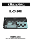
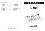
DMX CONTROLLER
PLBLMX1024
2
INDICE
NORME DI SICUREZZA........................................................................................................................... 5
CARATTERISTICHE................................................................................................................................... 5
PANNELLO FRONTALE .......................................................................................................................... 6
PANNELLO POSTERIORE....................................................................................................................... 9
OPERAZIONI GENERALI.......................................................................................................................10
CREAZIONE DI UNA SCENA ...............................................................................................................11
ESECUZIONE DI UNA SCENA.............................................................................................................11
CREAZIONE DI UN CHASE ..................................................................................................................12
ESECUZIONE DI UN CHASE................................................................................................................12
CREAZIONE DI UN AMBIENTE...........................................................................................................13
ESECUZIONE DI UN AMBIENTE.........................................................................................................13
CREAZIONE DI UN CONTROLLO MASTER.....................................................................................14
COPIA ........................................................................................................................................................14
INCOLLA ...................................................................................................................................................15
SPOSTA .....................................................................................................................................................15
MODIFICA ................................................................................................................................................15
SELEZIONE DI UN CHASE....................................................................................................................17
ASSEGNAZIONE DEI CURSORI ROTANTI .......................................................................................17
USO DEI CURSORI ROTANTI ..............................................................................................................17
ASSEGNAZIONE DELL’OFFSET AD UN CANALE..........................................................................18
USO DELL’OFFSET.................................................................................................................................18
SCRITTURA SU MEMORY CARD........................................................................................................18
LETTURA DA MEMORY CARD ...........................................................................................................19
IMPOSTAZIONE DELLA DISSOLVENZA SUI CANALI..................................................................19
ELIMINA ....................................................................................................................................................20
LAMPADA ................................................................................................................................................20
PROTEZIONE DATI ................................................................................................................................20
DATI TECNICI ..........................................................................................................................................20
3
TABLE OF CONTENTS
MAIN GUIDELINES.................................................................................................................................21
FEATURES.................................................................................................................................................21
FRONT PANEL.........................................................................................................................................22
REAR PANEL ............................................................................................................................................25
GENERAL OPERATIONS.......................................................................................................................26
CREATE A SCENE ...................................................................................................................................27
RUN A SCENE ..........................................................................................................................................27
CREATE A CHASE...................................................................................................................................28
RUN A CHASE..........................................................................................................................................28
CREATE AN ENVIRONMENT ...............................................................................................................29
RUN AN ENVIRONMENT......................................................................................................................29
CREATE A MASTER CONTROL ...........................................................................................................30
COPY..........................................................................................................................................................30
PASTE ........................................................................................................................................................31
MOVE.........................................................................................................................................................31
MODIFY.....................................................................................................................................................31
SELECT E CHASE ....................................................................................................................................33
FUNCTION WHEEL ASSIGMENT .......................................................................................................33
THE USE OF FUNCTION WHEEL........................................................................................................33
OFFSET CHANNEL ASSIGNMENT.....................................................................................................34
THE USE OF OFFSET .............................................................................................................................34
WRITE CF CARD......................................................................................................................................34
READ CF CARD .......................................................................................................................................35
SETUP OF SLOPE CHANNEL...............................................................................................................35
DELETE ......................................................................................................................................................36
GOOSENECK LAMP...............................................................................................................................36
DATA PROETCTION LOCK ..................................................................................................................36
TECHNICAL DATA .................................................................................................................................36
Rev.01- 07/08
4
NORME DI SICUREZZA
-
-
-
Leggere attentamente le istruzioni riportate nel presente manuale. All’interno di esso sono riportate
importanti informazioni di sicurezza, di uso e manutenzione. Tenere questo manuale sempre
assieme all’apparecchio, per poterlo consultare in futuro. Assicurarsi che qualsiasi altro operatore
utilizzi questa centralina, abbia con sé il presente manuale, affinché possa apprendere le relative
istruzioni.
Assicurarsi che nessun materiale infiammabile, liquido o metallico possa entrare all’interno della
centralina.
Se del liquido fosse penetrato, spegnere immediatamente la centralina e disconnettere
l’alimentazione.
Spegnere immediatamente la centralina in caso si riscontrassero problemi di funzionamento e
contattare immediatamente un nostro centro assistenza di zona.
Non aprire l’unità, all’interno non ci sono componenti che hanno bisogno di manutenzione
periodica.
Mai tentare di riparare da soli l’apparecchio. Riparazioni da parte di personale non qualificato
potrebbero causare danni. Ciò porta alla decadenza immediata della garanzia.
Questo apparecchio non è idoneo per uso domestico.
Dopo aver disimballato l’unità, verificare che non siano presenti danni. In caso affermativo non
utilizzare l’apparecchio e contattare immediatamente un nostro centro di assistenza di zona.
I materiali di imballaggio non devono essere lasciati in giro, dove potrebbero essere raggiunti da
bambini. Ciò potrebbe essere pericoloso.
Questa centralina deve essere utilizzata da personale adulto qualificato. Non permettere a persone
non qualificate o a bambini di giocare o manomettere l’apparecchio.
Non utilizzare mai l’apparecchio nelle seguenti condizioni:
o In zone soggette ad eccessiva umidità
o In zone soggette a vibrazioni o urti
o In zone con temperatura superiore a 40°C o inferiore a 2°C. Proteggere l’unità da zone di
eccessiva siccità o di eccessiva umidità: le condizioni ideali dovrebbero essere tra il 35% e 80%)
Non smontare o modificare l’apparecchio.
CARATTERISTICHE
-
-
Centralina DMX 512 per controllo di 512 canali DMX.
Possibilità di controllare fino a 21 apparecchi da 24 canali ciascuno + 1 apparecchio da 18 canali.
24 sliders frontali per un facile e veloce controllo di tutti i canali degli apparecchi.
Ampio display LCD.
144 scene eseguibili simultaneamente.
48 chases eseguibili simultaneamente. La velocità e la dissolvenza di ogni chase sono controllabili
separatamente o in contemporanea.
Fino a 200 step in ogni chase; 1600 step totali memorizzabili.
24 ambienti eseguibili simultaneamente.
3 sliders master, ognuno può essere assegnato ad un canale.
2 uscite parallele DMX 3 poli.
Uscite DMX optoisolate per prevenire rientri di disturbi elettrici provenienti dai proiettori.
Canali Pan/Tilt delle macchine, assegnabili ai due cursori rotanti.
La dissolvenza di un canale, quando un chase è in esecuzione, può essere configurata, tranne per i
canali Pan/Tilt (in cui la dissolvenza è fissa) e per i canali gobo e colori (per evitare effetti poco
gradevoli).
Microfono interno ed ingresso audio per controllo musicale.
Lampada 12V/3W
Switch interno per commutare su differenti tensioni (230V / 120V).
5
PANNELLO FRONTALE
PULSANTI DI SELEZIONE FIXTURE
Sono selezionabili 22 pulsanti di selezione fixture (21 fixtures da 24 canali + 1 fixtures da 8 canali).
Effettuata la selezione il LED corrispondente inizia a lampeggiare. E’ possibile attivare il pulsante [MULTI]
per selezionare più fixtures contemporaneamente.
DISPLAY INDIRIZZO DMX
Indica l’indirizzo DMX da impostare sulla rispettiva macchina.
6
SLIDERS E INDICATORI LED
Sul pannello frontale sono presenti 24 sliders ciascuno con il proprio indicatore led. Con tali sliders e i 22
pulsanti fixture, possono essere controllati tutti manualmente.
PULSANTI FUNZIONE
Nota: [NOME PULSANTE] indica la funzione del pulsante; [NOME PULSANTE] indica una funzione
addizionale collegata al pulsante.
[RELEASE]: quando c’è un’uscita su uno slider, premere il pulsante [RELEASE] e muovere lo slider, l’uscita
canale dello slider sarà così liberata.
[CLEAR]: la funzione di questo pulsante cambia a seconda dello stato in cui ci so trova.
[ALL OFF]: premere questo pulsante per cancellare tutte le uscite.
[COPY]: premere questo pulsante per copiare una scena, un chase o un ambiente.
[DEL]: premere questo pulsante per eliminare una scena, un chase, un ambiente, un dimmer, le
impostazioni di pan e tilt e del tempo di dissolvenza
[INSERT]: premere questo pulsante per inserire uno step durante la fase di programmazione.
[PASTE]: premere questo pulsante per incollare una scena, un chase o un ambiente.
[MOVE]: premere questo pulsante per spostare una scena, un chase o un ambiente.
[MODIFY]: premere questo pulsante per modificare una scena, un chase, un ambiente o un canale
dimmer.
[UNDO]: premere questo pulsante per uscire dal comando corrente.
[ENTER]: premere questo pulsante per confermare l’operazione corrente.
[PROGRAM]: premere questo pulsante per entrare nella fase di programmazione.
[Ch/En]: premere questo pulsante per passare dal Cinese all’Inglese
[SWAP]: Premere questo pulsante durante la fase di esecuzione dei programmi, per passare ad una
scena, un chase o gruppi di chase differenti (saranno eseguiti uno alla volta).
[LATCH]: premere questo pulsante per concatenare 2 o più scene / chase / gruppi di chase. In questo
caso gli elementi concatenati possono essere eseguiti contemporaneamente.
[FLASH]: Premere e tenere premuto questo pulsante quindi selezionare una scena, un chase o un
gruppo di chase da eseguire. Rilasciare il pulsante per terminare l’esecuzione.
7
[SLOPESET]: premere questo pulsante per impostare la dissolvenza su un canale (i canali Pan/Tilt,
controllati attraverso i due cursori rotanti hanno dissolvenza fissa).
[MANUAL]: premere questo pulsante per entrare in modalità manuale di controllo.
[SELCHASE]: premere questo pulsante per selezionare uno dei chase in esecuzione, per settare i suoi
elementi.
[IN_ALL]: quando un chase è in esecuzione premere questo pulsante e ruotare il cursore rotante per
impostare il tempo di esecuzione di ogni scena nel chase. Rilasciare il pulsante e ruotare il cursore
rotante per impostare la velocità dello step corrente.
[BLACKOUT]: quando l’indicatore led di questo pulsante è acceso, tutte le uscite sono impostate a zero.
[PAUSE]: premere questo pulsante per mettere in pausa tutti i chases in esecuzione.
[TAP]: l’intervallo tra due pressioni di questo pulsante impostano la velocità di esecuzione del chase
corrente.
[⇐]: esegue il chase precedente
[⇒]: esegue il chase successivo
[BACK]: premere questo pulsante per selezionare la scena precedente durante l’esecuzione manuale di
un chase.
[NEXT]: premere questo pulsante per selezionare la scena successiva durante l’esecuzione manuale di un
chase.
[AUTO]: premere questo pulsante per eseguire in maniera automatica il chase corrente nella modalità
preset.
[SMANUAL]: premere questo pulsante per eseguire in maniera manuale il chase corrente utilizzando i
pulsanti [BACK] e [NEXT].
[SOUND]: premendo questo pulsante l’esecuzione dei chases sarà effettuata in modalità musicale. La
sorgente audio può essere di tipo MIDI, tramite linea in ingresso o tramite microfono.
[STORE CF]: per memorizzare i dati dal controller alla memory card.
[SPAUSE]: per mettere in carica un singolo chase
[READ CF]: per trasferire i dati dalla memory card al controller
[SELOFFSET]: per selezionare l’offset dei cursori rotanti.
[SELROLL]: per selezionare i cursori rotanti,
[E/D/X]: abilita/disabilita il Pan (il led rosso acceso indica che la funzione è abilitata).
[E/D/Y]: abilita/disabilita il Tilt (il led rosso acceso indica che la funzione è abilitata).
[MULTI]: premere questo pulsante per selezionare contemporaneamente 2 o più fixtures (led acceso). Se
il led è spento può essere selezionata una sola fixture alla volta.
8
AREA DI MEMORIZZAZIONE
[CHASE1] e [CHASE2]: 2 gruppi di chase, ciascuno con 24 chases, totale 48 chases.
[SC1], [SC2], [SC3], [SC4], [SC5], [SC6]: 6 gruppi di scene, ciascuno con 24 scene, totale 144 scene.
[ENVIRO]: gruppo di ambienti, totale 24 ambienti .
[1÷24]: 24 pulsanti per uso delle scene, chases e ambienti.
CURSORI ROTANTI
[X/SPEED] e [Y/SLOPE]: permettono di controllare il Pan e Tilt delle fixtures (Pan e Tilt devono essere
impostati sui due cursori rotanti). Permettono inoltre di regolare la velocità e la dissolvenza dei chases e
dei gruppi di chases.
MASTER CONTROL
[DIMSEL1], [DIMSEL2], [DIMSEL3]: sono usati rispettivamente per abilitare o disabilitare i 3 sliders master,
i quali sono utilizzati per controllare il valore di uscita dei canali ad essi assegnati. I tre sliders funzionano
solo se i tre rispettivi pulsanti sono abilitati.
BLOCCO PROTEZIONE DATI
Il blocco protezione dati è utilizzato per preservare tutti i programmi impostati, da cancellazioni
accidentali.
CF MEMORY CARD E LAMPADA
E’ possibile collegare una lampada 6W 12VDC nel connettore XLR 3 poli posto sul pannello frontale. Tale
lampada può essere attivata con l’interruttore ON/OFF posizionato vicino.
La CF memory card è utilizzata per fare il backup di tutti i dati nel controller.
PANNELLO POSTERIORE
-
connettori XLR 3 poli DMX
ingresso audio tramite microfono interno o linea in ingresso
connettore MIDI
fusibile
interruttore generale di accensione
connettore di alimentazione.
presa di alimentazione variabile 100∼240 Vac – 50/60Hz
9
OPERAZIONI GENERALI
Assicurarsi che l’alimentazione elettrica sia corretta prima di dare tensione (100-240V 50/60Hz).
Accendere la centralina.
Selezione delle fixtures: i 24 pulsanti per selezionare una fixture sono posti in alto. Quando un led di tali
pulsanti è acceso, significa che a relativa fixture è selezionata. Se il led del pulsante [MULTI] è acceso,
possono essere selezionate 2 o più fixtures, altrimenti può essere selezionata solo una fixture alla volta.
Il display a led visualizzerà l’indirizzo DMX dell’ultima fixture selezionata. Una volta selezionata la fixture,
essa può essere controllata dai relativi sliders.
Uso degli sliders: dopo aver selezionato la fixture desiderata è possibile controllarla tramite gli sliders.
Muovere lo slider per vedere l’esecuzione della funzione da parte della fixture. Se durante il suddetto
movimento non accade nulla, portare il relativo slider al massimo, poi al minimo e ripetere il movimento
iniziale. Il led indicatore dello slider rimarrà acceso, ciò significa che dal canale in questione c’è un output
di dati. Se lo slider è in basso e il led lampeggia, l’uscita è nulla. Il comando manuale ha priorità rispetto
all’automatismo delle scene, chase e gruppi di chase. Premere il pulsante [RELEASE] e abbassare lo slider,
esso sarà liberato dall’impostazione del valore manuale ed il controllo tornerà all’automatico.
Controllo manuale:
Passo
Descrizione
1
Premere il pulsante [MANUAL] per attivare il controllo manuale
2
Premere [LIGHT X1] per selezionare la fixture desiderata.
3
Muovere gli sliders per vedere il movimento della fixture. Se la fixture non dà
risposta, portare lo slider verso l’alto, poi verso il basso. L’effetto desiderato
inizierà. In questo momento l’indicatore degli sliders sarà rosso, ciò significa
che il canale è in uso.
4
Premere ancora il pulsante [MANUAL] per disattivare il controllo manuale
NOTE:
1. Premere e tenere premuto il pulsante [RELEASE] quindi muovere lo slider desiderato per liberare il
canale. ATTENZIONE: se in esecuzione c’è una scena, un chase o un gruppo di chases che sta
utilizzando quel canale, la luminosità del led indicatore sarà più bassa.
2. Premere [CLEAR] per cancellare tutte le uscita manuali. Tutti i led indicatori degli slider si
spegneranno.
3. Premere il pulsante [ALL OFF] per cancellare tutte le uscite manuali. Nel frattempo anche le scene in
esecuzione si spegneranno
4. Il controllo manuale è prioritario su qualsiasi modalità automatica (SCENE, CHASE, GRUPPI DI CHASE)
[CLEAR]
1. quando il led indicatore della funzione [MANUAL] è attivo, premere [CLEAR] per cancellare tutte le
uscite manuali.
2. Quando il led indicatore di [SC1], [SC2], [SC3], [SC4], [SC5] e [SC6] è acceso, premere [CLEAR] per
chiudere tutte le scene in questa pagina.
3. Quando il led indicatore di [CHASE 1] e [CHASE 2] è acceso, premere [CLEAR] per chiudere tutti i
chases in questa pagina.
4. Quando il led indicatore [ENVIRO] è acceso, premere [CLEAR] per chiudere tutti gli ambienti.
Per l’uso del pulsante [CLEAR] in funzione dei comandi, vedere anche le descrizioni dei singoli comandi.
10
CREAZIONE DI UNA SCENA
Passo
1
2
3
4
5
6
7
Descrizione
Premere [PROGRAM] per entrare nella modalità programmazione
Selezionare [SC1] ÷ [SC6] per selezionare il gruppo dove memorizzare la scena. Il
led indicatore acceso indica che ci sono già scene memorizzata nel pulsante
Selezionare la fixture desiderata
Muovere gli sliders per scegliere la configurazione della fixture
Selezionare un pulsante tra [1A] e [24XYZ] per memorizzare lo step
Ripetere i passi 4 e 5 per memorizzare altri step
Premere [PROGRAM] per uscire salvando / [UNDO] per uscire senza salvare
NOTE:
1. Se il led indicatore di uno slider è acceso, il relativo canale sarà memorizzato nella scena. Se non si
desidera che tale canale non sia memorizzato, premere e tenere premuto il pulsante [RELEASE] e
muovere verso il basso lo slider del canale. In tal caso il led indicatore si spegnerà. Si raccomanda di
rilasciare tutti i canali non necessari per la scena, per evitare di avere situazioni inaspettate durante
l’esecuzione dei vari programmi.
2. E’ possibile usare il tasto [CLEAR] per rilasciare tutti i canali.
3. Se appare il messaggio di errore durante il salvataggio di una scena, è dovuto al fatto che una scena
già esistente è in esecuzione nel pulsante dove si sta cercando di memorizzarne una nuova.
ESECUZIONE DI UNA SCENA
Passo
1
2
3
Descrizione
Selezionare [SC1] ÷ [SC6] a seconda di dove sono memorizzate le scene
Il led indicatore lampeggerà rapidamente
Selezionare un pulsante tra [1A] e [24XYZ] per far eseguire una la scena. Il led
indicatore inizierà a lampeggiare lentamente (segno che la scena è in
esecuzione) e i led indicatori degli sliders lampeggeranno.
NOTE:
1. Premere [CLEAR] per chiudere tutte le scene nella pagina e tutte le uscite manuali
2. premere [ALL OFF] per chiudere le scene in esecuzione, i chases e gli ambienti e tutti i controlli
manuali
3. Se la scena in esecuzione sta utilizzando un canale che è anche sotto il controllo manuale, l’uscita
prioritaria sarà quella del controllo manuale. (Se il led indicatore dello slider è acceso fisso, l’uscita è
in manuale, se lo stesso lampeggia, l’uscita è in automatico, sotto il controllo della scena in
esecuzione).
11
CREAZIONE DI UN CHASE
Passo
1
2
3
4
5
6
7
Descrizione
Premere [PROGRAM] per entrare nella modalità programmazione
Selezionare [CHASE1] o [CHASE2] per selezionare il gruppo dove memorizzare il
chase. Il led indicatore acceso indica che ci sono già chases memorizzati nel
pulsante
Selezionare un pulsante tra [1A] e [24XYZ] come numero per il chase
A questo punto è possibile selezionare la scena desiderata o la fixture per
impostare la configurazione desiderata per il proiettori. E’ sempre possibile
aprire una scena e riconfigurare gli effetti relativi a gobo, colori, pan, tilt ecc.
Una volta che l’effetto desiderato è stato ottenuto è possibile salvarlo con i
parametri di default per velocità di esecuzione e tempo di dissolvenza (3 sec.),
oppure modificare questi tramite i due cursori rotanti.
Premere [ENTER] per aggiungere l’effetto all’interno del chase. Ripetere i passi
da 4 a 6 per memorizzare altre configurazione all’interno dello stesso chase
Premere [PROGRAM] per uscire salvando / [UNDO] per uscire senza salvare
ESECUZIONE DI UN CHASE
Passo
1
2
3
Descrizione
Selezionare [CHASE1] o [CHASE2] a seconda di dove sono memorizzati i chases
Il led indicatore lampeggerà rapidamente se esistono dei chases già inseriti
Selezionare un pulsante tra [1A] e [24XYZ] per far eseguire una la scena. Il led
indicatore smetterà di lampeggiare (segno che il chase è in esecuzione). Se più
chases sono in esecuzione contemporaneamente il led indicatore del chase
precedente a quello selezionato lampeggerà.
NOTE:
1. A seconda delle modalità di lampeggio dei led indicatori, si ha un significato: lampeggio rapido,
significa che c’è già un chase esistente, ma non è in esecuzione; acceso fisso significa che il chase è in
esecuzione ed è anche pronto per essere eventualmente editato.
Durante l’esecuzione di un chase si possono utilizzare i seguenti comandi:
[⇒]: si passa all’esecuzione del chase successivo;
[⇐]: si passa all’esecuzione del chase precedente;
[AUTO]: il case viene eseguito in modalità automatica;
[SMANUAL]: il chase viene eseguito in modalità manuale;
[SOUND]: il chase viene eseguito in modalità musicale;
[SPAUSE]: si mette in pausa l’esecuzione del chase;
[BACK]: si passa allo step precedente se il chase è in esecuzione manuale
[NEXT]: si passa allo step successivo se il chase è in esecuzione manuale;
12
PREMERE e mantenere premuto [IN-ALL]: ruotare il cursore rotante X per variare il valore della velocità di
esecuzione, ruotare il cursore rotante Y per variare il valore della dissolvenza. Se il pulsante [IN-ALL] non
viene premuto la regolazione riguarda solo la velocità e la dissolvenza di un singolo passo. Prima di fare
la regolazione con il pulsante [IN-ALL] assicurarsi che i pulsanti [SELOFFSET] e [SELJOY] siano inattivi (led
indicatore spento).
2. Premere [TAP] 2 volte. L’intervallo di tempo tra le due pressioni determinerà la velocità di esecuzione
delle scene nel chase.
3. Premere [CLEAR] per chiudere tutti i chases nella pagina. Premere [ALLOFF] per chiudere tutte le
uscite.
4. Se il chase in esecuzione ed il controllo manuale interessa lo stesso canale interessato dalla modalità
automatica, prevarrà la prima situazione (controllo manuale su automatico). Se il led indicatore dello
slider del canale è acceso fisso, è attivata la modalità manuale per quel canale, se il led lampeggia, è
attivata la modalità manuale per quel canale.
CREAZIONE DI UN AMBIENTE
Passo
1
2
3
4
5
Descrizione
Mandare in esecuzione le scene che si vogliono aggiungere nell’ambiente
Mandare in esecuzione i chases che si vogliono aggiungere nell’ambiente,
regolando la velocità di esecuzione e la dissolvenza
Premere [PROGRAM] per entrare nella modalità programmazione
Premere [ENVIRO]
Selezionale un pulsante dove salvare l’ambiente. Se all’interno è presente un
altro pulsante il led indicatore sarà acceso
ESECUZIONE DI UN AMBIENTE
Passo
1
2
3
Descrizione
Premere [ENVIRO]
Se esiste già un ambiente memorizzato in un pulsante, il led indicatore
lampeggerà
Selezionare il pulsante in cui si trova l’ambiente desiderato. Il led indicatore
lampeggerà lentamente e le scene ed i chases presenti saranno attivati
NOTE:
1. Premere [CLEAR] per chiudere tutti gli ambienti. Premere [ALLOFF] per chiudere tutte le uscite.
13
CREARE UN CONTROLLO MASTER
I tre pulsanti [DIMSEL1], [DIMSEL2], [DIMSEL3] sono collegati ai tre rispettivi sliders master.
Per creare un master control seguire i passi indicati:
Passo
1
2
3
4
5
Descrizione
Premere [PROGRAM] per entrare in modalità programmazione
Selezionare uno dei tre pulsanti [DIMSEL1], [DIMSEL2], [DIMSEL3]
Selezionare l’indirizzo DMX del dimmer
Muovere gli slider che si vogliono aggiungere all’interno del master fino a
quando non si accende il led indicatore dello slider. Si possono inserire tutti gli
slider desiderati.
Premere ancora uno dei tre pulsanti [DIMSEL1], [DIMSEL2], [DIMSEL3] per
memorizzare il controllo master.
NOTE:
1. se ad esempio si ha un dimmer 8 canali, con indirizzo 25 (corrispondente all’indirizzo di start della
seconda fixture), seguire i passi indicati per memorizzare il controllo master 1.
[PROGRAM] → [DIMSEL1] → selezionare il pulsante fixture 2 → muovere gli slider 1÷8 fino a
quando i rispettivi led indicatori non si accendono → [DIMSEL1]
A questo punto il master control 1 è pronto: lo slider Master 1 controllerà le uscite dei canali 1÷8 della
fixture 2.
COPIA
Questo pulsante permette di copiare temporaneamente in memoria una scena, un chase o un ambiente
per poi incollarlo (col relativo pulsante):
Passo
1
2
3
4
Descrizione
Premere [COPY]
Selezionare ciò che si vuole copiare [SC1], [SC2], [SC3], [SC4], [SC5], [SC6],
[CHASE1, [CHASE2] o [ENVIRO]
Selezionare il pulsante da copiare. Se il led indicatore è acceso, significa che è
possibile copiarlo.
Effettuata la selezione, il contenuto del pulsante è copiato in memoria.
NOTE:
1. Per copiare ad es. il pulsante [1/A] del [CHASE1]
[COPY] → [CHASE1] → [1/A]
14
INCOLLA
Passo
1
2
3
4
Descrizione
Premere [PASTE]
Selezionare ciò che si vuole incollare [SC1], [SC2], [SC3], [SC4], [SC5], [SC6],
[CHASE1, [CHASE2] o [ENVIRO]
Selezionare il pulsante dove incollare.
Effettuata la selezione, il contenuto della memoria è copiato in un pulsante.
NOTE:
1. Per copiare ad es. il contenuto della memoria nel pulsante [2/B]
[PASTE] → [CHASE1] → [2/B].
In questo caso, facendo riferimento a quanto detto spora, i pulsanti [1/A] e [2/B] avranno lo stesso
contenuto.
SPOSTA
Passo
1
2
3
4
5
Descrizione
Premere [MOVE]
Selezionare ciò che si vuole muovere [SC1], [SC2], [SC3], [SC4], [SC5], [SC6],
[CHASE1, [CHASE2] o [ENVIRO]
Selezionare il pulsante da spostare.
Selezionare il pulsante destinazione.
Il contenuto del primo pulsante sarà spostato sul secondo.
NOTE:
1. Per muovere ad es. il contenuto del pulsante [1/A] del [CHASE1] nel pulsante [2/B] del [CHASE1]
[MOVE] → [CHASE1] → [1/A] → [2/B].
In questo caso, il contenuto del pulsante [1/A] sarà spostato in [2/B] e [1/A] risulterà vuoto.
MODIFICA
[MODIFY] può essere utilizzato per modificare una scena, un chase un ambiente o un set dimmer.
A. MODIFICA DI UNA SCENA
Passo
Descrizione
1
Premere [MODIFY] per entrare in modalità modifica
2
Selezionare la pagina che si vuole modificare tra [SC1], [SC2], [SC3], [SC4], [SC5],
[SC6]
3
Una volta selezionato, il led indicatore di quelle scene, si illuminerà
4
Selezionare le scene da modificare. I led indicatori delle scene non selezionate
saranno spenti. Saranno accesi solo quelli da modificare.
5
Muovere gli sliders per impostare i nuovi valori; è inoltre possibile aggiungere
nuovo canali o rilasciarli tramite il pulsante [RELEASE]
6
Dopo la modifica, premere il pulsante relativo alla scena dove si intende
memorizzare. Se il pulsante è lo stesso selezionato nel punto 4, il contenuto
precedente sarà sovrascritto, altrimenti la nuova scena andrà a memorizzarsi nel
nuovo pulsante scelto
7
Ripetere i punti 3 ÷ 6 per modificare un’altra scena, oppure premere [MODIFY] o
[UNDO] per uscire.
15
NOTE:
1. in ogni momento premere [UNDO] per uscire dalla modalità modifica.
B. MODIFICA DI UN CHASE
Passo
Descrizione
1
Premere [MODIFY] per entrare in modalità modifica
2
Selezionare la pagina che si vuole modificare tra [CHASE1] e [CHASE2]
3
Una volta selezionato, il led indicatore di quei pulsanti all’interno del quale sono
memorizzati dei chase, si illuminerà
4
Selezionare i chases da modificare. I led indicatori dei chases non selezionati
saranno spenti. Saranno accesi solo quelli da modificare.
5
Premere [BACK] o [NEXT] per selezionare la scena da modificare all’interno del
chase
6
Una volta selezionata la scena, muovere gli sliders per impostare i nuovi valori.
Premere [ ENTER] per salvare le modifiche
7
Se necessario utilizzare il pulsante [DEL] per eliminare una scena
(eventualmente premere [BACK] o [NEXT] per individuare tele scena)
8
Utilizzare [INSERT] per inserire una scena se necessario. Premere [BACK] o [NEXT]
per individuare il punto di inserimento. Premere [INSERT] ancora per copiare la
scena corrente ed inserirla precedentemente al punto di inserimento, inoltre è
possibile utilizzare [PASTE] per incollare la scena copiata nel punto di
inserimento. Premere [ENTER] per confermare.
9
Dopo la modifica, premere il pulsante relativo al chase dove si intende
memorizzare. Se il pulsante è lo stesso selezionato nel punto 4, il contenuto
precedente sarà sovrascritto, altrimenti il nuovo chase andrà a memorizzarsi nel
nuovo pulsante scelto
10
Ripetere i punti 3 ÷ 9 per modificare un altro chase, oppure premere [MODIFY] o
[UNDO] per uscire.
NOTE:
1. in ogni momento premere [UNDO] per uscire dalla modalità modifica.
C. MODIFICA DI UN AMBIENTE
Passo
Descrizione
1
Premere [MODIFY] per entrare in modalità modifica
2
Premere [ENVIRO]
3
Il led indicatore di quei pulsanti all’interno del quale sono memorizzati degli
ambienti, si illuminerà
4
Selezionare l’ambiente desiderato da modificare. I led indicatori degli ambienti
non selezionati saranno spenti. Saranno accesi solo quelli da modificare.
5
Eseguire o chiudere le scene o i chases da inserire o rimuovere dall’ambiente
6
Premere [ENVIRO]
7
Dopo la modifica, premere il pulsante relativo all’ambiente dove si intende
memorizzare. Se il pulsante è lo stesso selezionato nel punto 4, il contenuto
precedente sarà sovrascritto, altrimenti il nuovo ambiente andrà a memorizzarsi
nel nuovo pulsante scelto
8
Ripetere i punti 3 ÷ 7 per modificare un altro chase, oppure premere [MODIFY] o
[UNDO] per uscire.
NOTE:
1. in ogni momento premere [UNDO] per uscire dalla modalità modifica.
16
D. MODIFICA DI UN SET DIMMER
Passo
Descrizione
1
Premere [MODIFY] per entrare in modalità modifica
2
Premere [DIMSEL1], [DIMSEL2] o [DIMSEL3]
3
Selezionare le fixture desiderate
4
Muovere gli sliders che si vogliono aggiungere nel dimmer set fino a quando i
relativi led indicatori non si illumineranno
5
Dopo la modifica premere il pulsante relativo al set dimmer selezionato al punto
2, oppure premere [UNDO] per uscire senza salvare.
SELEZIONE DI UN CHASE
Nella centralina possono essere eseguiti in totale fino a 48 chases simultaneamente, ma soolo uno alla
volta può essere modificato. L’ultimo chases attivato sarà pronto per la modifica, gli altri no. Utilizzare il
pulsante [SELCHASE] per selezionare il chase da modificare.
Passo
1
2
3
4
Descrizione
Premere [SELCHASE]
Premere [CHASE1] o [CHASE2] a seconda di dove si vuole entrare
I led indicatori di quei pulsanti con chase inseriti saranno accesi
Selezionare un chase per la modifica. Il chase selezionato avrà il led indicatore
acceso fisso, gli altri avranno il led lampeggiante.
ASSEGNAZIONE DEI CURSORI ROTANTI
Il pan e tilt di una fixture possono essere assegnati ai due cursori rotanti per un più semplice controllo:
Passo
1
2
3
4
5
Descrizione
Premere [PROGRAM] per entrare in modalità programmazione
Selezionare con [⇐] o [⇒]
Selezionare la fixture desiderata
Muovere gli slider del pan e tilt della fixture selezionata, fino a quando i led
indicatori degli sliders non si illumineranno
Premere [⇐] o [⇒] di nuovo per salvare ed uscire
USO DEI CURSORI ROTANTI
I canali assegnati ai cursori rotanti possono essere controllato da tali cursori.
Ipotizzato che ad esempio il canale 5 di una tale fixture sia il pan e che questo sia stato assegnato al
relativo cursore rotante, per utilizzarlo:
1. premere [MANUAL] per attivare la modalità manuale e premere [SELJOY]
2. selezionate la prima fixture
3. premere [E/DX] per attivare il cursore rotante X
4. ruotare per modificare il valore di uscita del canale 5. Il led indicatore del canale 5 sarà acceso.
L’uso del cursore rotante Y è lo stesso.
17
ASSEGNAZIONE DELL’OFFSET AD UN CANALE
Sui canali assegnati ai cursori rotanti è possibile assegnare un offset. I valori di offset possono essere
controllati tramite i cursori rotanti.
Passo
1
2
3
4
5
6
Descrizione
Premere [PROGRAM] per entrare in modalità programmazione
Premere [SELOFFSET] per selezionare il valore del cursore rotante
Premere [E/DX] o [E/DY]
Selezionare la fixture desiderata
Muovere lo slider da assegnare al cursore rotante fino a quando il relativo led
non si illumina
Premere [E/DX] o [E/DY] di nuovo per salvare ed uscire
NOTE:
1. supponendo per esempio che il canale 5 della fixture 1 sia il pan, assegniamo a questo un offset X
[PROGRAM] → [SELOFFSET] → [E/DX] → Fixture1 → Muovere lo slider del canale 5 fino a
quando il led indicatore non sia acceso → [E/DX].
A questo punto il canale 5 è assegnato a [E/DX]
USO DELL’OFFSET
Il canale a cui è stato assegnato un offset nel cursore rotante, può essere controllato, attraverso tale
offset.
Esempio esplicativo:
Supponendo che ci sia un chase con due scene, il valore del primo canale della prima scena sia 50; il
valore del primo canale della seconda scena sia 200.
Se è stato assegnato al primo canale un offset [E/DX], ruotando la ruota X in senso antiorario una volta, il
valore di offset si ridurrà di 1 per cui il primo canale della prima scena diventerà 49 e quello della
seconda scena 199.
Ruotando in senso orario si aggiungerà un valore.
NOTE:
1. [CHASE1] e [CHASE2] dovrebbero essere attivati
2. il led indicatore di [SELOFFSET] dovrebbe essere attivato
3. [E/DX] è per il cursore rotante X, [E/DY] per il cursore rotante Y
4. premere [RELEASE] e ruotare il cursore rotante per rilasciare l’offset; l’uscita tornerà ai valori originali.
SCRITTURA SU MEMORY CARD
I dati della centralina possono essere salvati su una memoria Compact Flash (CF)
Passo
1
2
3
4
Descrizione
Premere [PROGRAM] per entrare in modalità programmazione
Premere [STORECF]
Viene eseguita l’operazione di backup dei dati fino a quando il led della CF
lampeggia
Alla fine della scrittura dei dati, la centralina uscirà automaticamente dalla
modalità programmazione
18
NOTE:
1. Ogni nuova scrittura sovrascriverà i dati preesistenti sulla CF
2. Mentre il led indicatore lampeggia non rimuovere la CF dallo slot in quanto il procedimento di
scrittura è in corso
3. Durante la fase di scrittura sulla CF, l’esecuzione dei chases viene interrotta ed i pulsanti disabilitati,
fino a quando il processo di scrittura non sarà terminato
LETTURA DA MEMORY CARD
Passo
1
2
3
4
Descrizione
Premere [PROGRAM] per entrare in modalità programmazione
Premere [LOADCF]
Viene eseguita l’operazione di lettura dei dati fino a quando il led della CF
lampeggia
Alla fine della lettura dei dati, la centralina uscirà automaticamente dalla
modalità programmazione
NOTE:
1. Ogni nuova lettura sovrascriverà i dati preesistenti sulla centralina
2. Mentre il led indicatore lampeggia non rimuovere la CF dallo slot in quanto il procedimento di
lettura è in corso
3. Durante la fase di scrittura sulla CF, l’esecuzione dei chases viene interrotta ed i pulsanti disabilitati,
fino a quando il processo di lettura non sarà terminato
IMPOSTAZIONE DELLA DISSOLVENZA SUI CANALI
I canali assegnati ai cursori rotanti avranno automaticamente una dissolvenza durante l’esecuzione dei
chase. Per gli altri canali è possibile impostare una dissolvenza
Passo
1
2
3
4
5
Descrizione
Premere [PROGRAM] per entrare in modalità programmazione
Premere [SLOPESET]
Selezionare la fixture desiderata
Selezionare il canale al quale si vuole assegnare la dissolvenza, fino a quando
l’indicatore a led dello slider non si accende. Premere [RELEASE] e muovere lo
slider per rilasciare il canale selezionato.
Premere di nuovo [SLOPESET]. Il setup è così terminato. La dissolvenza sarà cosi
assegnata el canale quando il chase andrà in esecuzione.
ESEMPIO:
Per impostare la dissolvenza sui canali 5 e 6 di una fixture:
premere [PROGRAM] → [SLOPESET] → Select fixture [1] → muovere gli sliders 5 e 6 fino a quando i
relativi led indicatori non si accendano → premere [SLOPESET]
19
ELIMINA
Passo
1
2
3
4
Descrizione
Premere [DEL]
Selezionare ciò che si vuole eliminare tra [SC1], [SC2], [SC3], [SC4], [SC5], [SC6],
[CHASE1], [CHASE2], [ENVIRO], [E/DX], [E/DY], [SLOPESET], [DIMSEL1], [DIMSEL2]
o [DIMSEL3]
Selezionare il numero di pulsanti da eliminare (non necessario per E/DX], [E/DY]
e [SLOPESET]
Cancellazione effettuata
ESEMPIO:
Per eliminare il chase nel pulsante 2/B del CHASE 1:
[DEL] → [CHASE1] → [2/B]
LAMPADA
La lampada ha le seguanti caratteristiche: 12V – 0,5A. Utilizzare sempre la lampada corretta
PROTEZIONE DATI
Quando la chiave è girata nella posizione “Program”, il controller è sbloccato per la modifica dei dati,
quando la chiave è girata nella posizione “Run”, il controller è bloccato, non è possibile nessuna
operazione di modifica. E’ possibile effettuare solo controllo manuale, attivare o disattivare una scena,
un chase, un ambiente.
DATI TECNICI
PLBLMX1024
Alimentazione:
Dimensioni:
Peso:
100-240V - 50/60Hz
LxPxH mm.738x360x100
kg. 10,5
20
MAIN GUIDELINES
-
-
-
Read the instruction in this manual carefully and thoroughly, as they give important information
regarding safety during use and maintenance. Keep this manual with the unit, in order to consult it
in the future. If the unit is sold or given to another operator, make certain that it always has its
manual, to enable the new owner to read about its operation and relative instructions.
DO NOT make any inflammable liquids, water or metal objects enter the unit
Should any liquid be spilled on the unit, DISCONNECT the power supply to the unit immediately
STOP using the unit immediately in the event of serious operation problems and either contact your
local dealer for a check or contact us directly
DO NOT open the unit — there are no user serviceable parts inside
NEVER try to repair the unit yourself. Repairs by unqualified people could cause damage or faulty
operation. Contact your nearest dealer.
This unit is NOT intended for home use.
After having removed the packaging check that the unit is NOT damaged in any way. If in doubt,
DON'T use it and contact an authorized dealer.
Packaging material (plastic bags, polystyrene foam, nails, etc.) MUST NOT be left within children's
reach, as it can be dangerous.
This unit must only be operated by adults. DO NOT allow children to tamper or play with it.
NEVER use the unit under the following conditions:
o In places subject to excessive humidity.
o In places subject to vibrations or bumps.
o In places with a temperature of over 40℃ or less than 2℃. Protect the unit from excessive
dryness or humidity (ideal conditions are between35% and 80%).
DO NOT dismantle or modify the unit
FEATURES
-
512 DMX512 control channels, compatible with DMX512/1990 standard;
Control up to 22 fixtures, each with up to 24 channels. (The last fixture is with only 8 channels);
24 sliders on the front panel for easy and fast control of all the channels in the fixture;
Big size LCD display with language selection (Chinese/English);
144 scenes for direct output and simultaneously running;
48 chases run simultaneously. Speed and slope of each chase are adjustable either separately or
together;
Up to 200 steps in each chase; totally 1600 steps can be stored;
24 environments run simultaneously;
3 master sliders, each can be assigned with any channels;
3-pin DMX out × 2;
Photoelectric isolated data output, resistant to 3KVDC, preventing the controller from being
damaged by the electric leakage from the fixture.
All the pan/tilt channels in different fixtures can be assigned to the function wheels.
The slope channel when a chase is running can be configured, in which the pan/tilt slope is fixed and
the gobo/color channels can be set as without slope to avoid unexpected effect.
Built-in microphone and audio input for sound activation.
12V/3W gooseneck lamp.
Built-in switching power supply, suitable for all countries.
21
FRONT PANEL
FIXTURE SELEXTION BUTTONS
22 fixture selection buttons, each with 24 fixed DMX channels for the fixture. (Only 8 channels are for the
last fixture.)
Once selected, the LED indicator on the button will be flashing. Activate Multi (LED indicator on) to open
more fixtures.
DMX ADDRESS CODE DISPLAY
To display the DMX address that should be set to the selected fixture.
22
SLIDERS AND LED INDICATORS
There are 24 sliders, each with an LED indicator, on the front panel. With these sliders and the 22 fixture
selection buttons, all 512 channels can be controlled directly by manual.
FUNCTION BUTTONS
Note: [BUTTON NAME] indicates the function of the button; [BUTTON NAME] indicates the additional
function of the button.
[RELEASE]: When there is output in the slider, press [RELEASE] and move the slider, then the channel of
the slider will be released.
[CLEAR]: Operations on this button will be different in different status.
[ALLOFF]: Press this button to clear all output.
[COPY]: Press this button to copy a scene, a chase or an environment.
[DEL]: To delete a scene, a chase, an environment, a dimmer, the pan/tilt channel setting, or the slope
channel setting
[INSERT]: Press this button to insert a step when programming.
[PASTE]: Press this button to paste a scene, a chase or an environment.
[MOVE]: Press this button to move a scene, a chase or an environment.
[MODIFY]: Press this button to modify a scene, a chase, an environment or a dimmer channel.
[UNDO]: Press this button to exit the current command.
[ENTER]: Press this button to confirm the operation.
[PROGRAM]: Press this button to enter programming.
[Ch/En]: Press this button to toggle Chinese/English
[SWAP]: Press this button to swap the running of a different scene /chase / chase group (only one
running at a time)
[LATCH]: Press this button to latch two or more scenes /chases / chase groups, so that they can run
simultaneously.
[FLASH]: Press and hold this button, and then select a scene /chase /chase group to run it; Release the
button to close the running.
[SLOPESET]: Press this button to set a channel with slope. (The pan/tilt channels controlled by the
function wheels are fixed with slope.
23
[MANUAL]: Press this button to enter manual control mode.
[SELCHASE]: Press this button to select one of the running chases for setting of its running.
[IN_ALL]: When a chase is running, press this button and roll the function wheel to adjust the running
time of every scene in the chase. Release this button and roll the function wheel to adjust the speed of
the current step.
[BLACKOUT]: When LED indicator of this button is on, all outputs are zero.
[PAUSE]: Press this button to pause all running chases..
[TAP]: The interval time between two pressings of this button will be the running time of the current
chase.
[⇐]:Chase runs backward.
[⇒]: Chase runs forward.
[BACK]: Press this button to output the previous scene from the manual running chase.
[NEXT]: Press this button to output the next scene from the manual running chase.
[AUTO]: Press this button to make the chase auto running in preset mode.
[SMANUAL]: Press this button to manually run the chase [BACK] for previous scene, [NEXT] for next
scene.
[SOUND]: Press this button, the chase running will be in sound activation mode, audio source from MIDI
or the surrounding sound.
[SPAUSE]: To pause a single chase
[STORECF]: To store the data from the controller to the CF memory card.
[READCF]: To read data from the CF memory card.
[SELOFFSET]: To set the offset to the function wheels.
[SELROLL]: To set the joystick to the function wheel.
[E/D/X]: Disable/Enable X (pan); LED indicator on means enabled.
[E/D/Y]: Disable/Enable Y (tilt); LED indicator on means enabled.
[MULTI]: Press this button to select two or more fixtures (LED indicator on); If the LED indicator of this
button is off, only one fixture can selected.
24
STORAGE AREA
[CHASE1] & [CHASE2]: 2 chase groups, each with up to 24 chases, total 48 chases.
[SC1], [SC2], [SC3], [SC4], [SC5], [SC6]: 6 scene groups, each with up to 24 scenes, total 144 scenes.
[ENVIRO]: Environment groups, with 24 environments.
[1÷24]: 24 number buttons for use of scenes, chases and environments.
FUNCTION WHEELS
[X/SPEED] & [Y/SLOPE]: Use to control the pan/tilt of the fixtures (the pan/tilt channels should be preset
to the function wheels) and speed/slope adjustment of chase and chase group.
MASTER CONTROL
The master control buttons [DIMSEL1], [DIMSEL2], [DIMSEL3]: are respectively used to enable/disable
and setup the three master controls Master sliders, Master1, Master2 & Master3 are used to control the
maximum output value of the assigned channels. They work only when [DIMSEL1], [DIMSEL2],
[DIMSEL3] are enabled (LED indicator on).
DATA PROTECTION LOCK
The data protection lock is used to prevent the preset programs from being deleted by
accident.
CF MEMORY CARD AND GOOSENECK LAMP
A 6W 12VDC gooseneck lamp can be plugged into the 3PIN XLR socket on the front panel, with power
on/off switch.
CF memory card is used to backup the data in the controller.
REAR PANEL
-
3-PIN XLR DMX-out socket × 2.
Audio input, by built-in microphone or external audio input.
MIDI interface for MIDI control.
Fuse.
Power switch, with LED indicator.
Power socket, suitable for 100~240VAC 50/60Hz power supply.
25
GENERAL OPERATIONS
Power on: Please confirm the power supply is correct for the controller before connection. After power
on, the controller will start resetting. You may see the LED indicators flashing.
Fixture selection: When the LED indicator of a button is flashing, it means a fixture is selected. When the
LED indicator of [MULTI] is on, two or more fixtures can be selected; otherwise, only one fixture can be
selected at a time. The LED display will show the DMX address code of the last fixture. Once the fixtures
are selected, they can be controlled with the sliders.
The use of sliders: After selecting the desired fixtures, you can control them with the sliders. Move the
sliders to see the running of the fixture. If the fixture gives no response, move the slider to the bottom
and them move up again. At this time the LED indicator of the slider will be on; it means there is data
output in the channel. When the slider is at the bottom and the LED indicator is flashing, it means the
output value is 0. Manual output is prior to the output of a running scene, chase or chase group. Press
[RELEASE] and then move the slider, it will release the manual output of the channel.
Manual control:
Step
Description
1
Press [MANUAL] to activate manual control mode
2
Press [LIGHT X1] select the desired fixtures.
3
Move the sliders to see the running of the fixture. If the fixture gives no
response, move the slider to the bottom and them move up again till it shows
the desired effect. At this time the LED indicator of the slider will be on; it
means the channel is in use.
4
Press [MANUAL] again to inactivate the manual control mode
NOTE:
1. Press and hold [RELEASE] then move a slider to release the channel and the LED indicator will be off.
But, if there is a scene/ chase/ chase group running on that channel, the brightness of the LED
indicator will change according to the output value.
2. Press [CLEAR] to clear all manual output. All the LED indicators of the sliders will be off.
3. Press [ALL OFF] to clear all manual output. All the LED indicators of the sliders will be off, and the
4. running scene, chase or environment will be closed
5. Manual output is prior to the output of a running scene /chase /chase group
[CLEAR]
1. When the LED indicator of [MANUAL] is on, press [CLEAR] to clear all manual output.
2. When one of the LED indicators of [SC1], [SC2], [SC3], [SC4], [SC5] & [SC6] is on, press [CLEAR] to close
all the scenes in that page.
3. When one of the LED indicators of [CHASE 1] & [CHASE 2] is on, press [CLEAR] to close all the
environments.
4. When the LED indicator of [ENVIRO] is on, press [CLEAR] to close all the environments.
For the use of [CLEAR] in the commands, please see the description of the commands.
26
CREATE A SCENE
Step
1
2
3
4
5
6
7
Description
Press [PROGRAM] to enter programming mode.
Select one off [SC1] ÷ [SC6] to store the scene. If the LED indicator is on, it means there
is an existing scene in the button.
Select the desired fixtures.
Move the sliders to adjust the lighting effects.
Select one number from [1A] and [24XYZ] to store the step.
Repeat Step 4—5 to store another step.
Press [PROGRAM] / [UNDO] to exit the programming mode.
NOTE:
1. If the LED indicator of the slider is on, then the channel will be stored into the scene. If you don’t
want to save the value of a certain channel, press and hold [RELEASE] and then move the slider to
release the channel, the LED indicator of the slider will be off. It is recommended to release the
unnecessary channels to avoid unexpected lighting effects.
2. Also, you can press [CLEAR] to release all the channels.
3. If it prompts error when saving a scene, it means there is an existing scene running in the number
button.
RUN A SCENE
Step
1
2
3
Description
Select [SC1] ÷ [SC6] in which the scene is stored.
The LED indicators of the number buttons with existing scenes will rapidly flash.
Select a number button to run a scene. Once selected, the LED indicator of the
number button will slowly flash, which means the scene is now running, and the
LED indicators of the sliders will flash.
NOTE:
1. Press [CLEAR] to close all the scenes in the page and all the manual output.
2. Press [ALL OFF] to close the running scenes, chases and environment, as well as manual output.
3. If the running scene is using the same channel under manual control, the output will be by manual
but not by the scene. (If the LED indicator of the slider is full on, the output is by manual; but if the
LED indicator of the slider is flashing, the output is by the scene.)
27
CREATE A CHASE
Step
1
2
3
4
5
6
7
Description
Press [PROGRAM] to enter programming mode.
Select [CHASE1] o [CHASE2] to store the chase. If the LED indicator of the button
is on, it means there is an existing chase in it.
Select a number from [1A] e [24XYZ] as the number of the chase.
A Now, you can select the desired scene or select a fixture to adjust the desired
lighting effect.
You can even open a scene and then re-adjust the effect of the scene by
moveing the sliders of Gobo, Color or pan/tilt to the right position.
Once the lighting effect is adjusted, it can be saved with the default running
speed as 3 sec and the default slope as 3 sec, too. Both are changeable by the
function wheels.
Press [ENTER] Once the lighting effect is adjusted, it can be saved with the
default running speed as 3 sec and the default slope as 3 sec, too. Both are
changeable by the function wheels.
Press [PROGRAM] to save and exit. Anytime press / [UNDO] to exit the
programming without saving.
RUN A CHASE
Step
1
2
3
Description
Select [CHASE1] and [CHASE2] in which the desired chase is in.
The LED indicator of the number button with an existing chase will flash rapidly.
Select the desired number button to run the chase. The LED indicator will stop
flashing, which means that the chase is now running. If more chases are running
simultaneously, then the LED indicator of the previous running chase number
button will slowly flash.
NOTE:
1. Different flashes of the number button LED indicator means different status. Rapid flash means that
there is an existing chase in the number button but not running. Slow flash means that the chase is
running and not for editing. Full on means the chase in running and ready for editing.
The followings can be edited when the chase is running:
[⇒]: Chase runs forward
[⇐]:Chase runs backward
[AUTO]: Chase runs under auto mode
[SMANUAL]: Chase runs under manual control mode
[SOUND]: Chase runs under sound activation mode
[SPAUSE]: To pause the chase running
[BACK]: To output the previous step of the chase under manual mode.
[NEXT]: To output the next step of the chase under manual mode.
28
Press and hold [IN-ALL]: Then roll the X function wheel to adjust the running speed; or roll the Y function
wheel to adjust the running slope. If [IN-ALL] is not pressed, the adjustment is for the speed/slope of a
single scene step in the chase.
Before adjustment, please make sure [SELOFFSET] and [SELJOY] are inactivated (LED indicator off)
1. Press [TAP] twice, the interval time between the two pressings will be the running speed of the
scenes in the chase.
2. Press [CLEAR] to close all chases in the page. Press [ALLOFF] to close all output.
3. If the running chase and the manual control are using the same channel, only the manual output will
be sent. (If LED indicator of slider is full on, it is manual output; if flashing, the output is by a running
chase.
CREATE AN ENVIRONMENT
Step
1
2
3
4
5
Description
Run the scenes that you want to add into the environment.
Run the chases that you want to add into the environment, and adjust the
running speed/slope.
Press [PROGRAM] to enter programming mode.
Press [ENVIRO]
Select a number button to save the environment. If there is an existing
environment in the number button, the LED indicator will be on.
RUN AN ENVIRONMENT
Step
1
2
3
Description
Press [ENVIRO]
If there is an existing environment in the number button, the LED indicator will
be flashing.
Select the number button in which the environment is. The LED indicator of the
number button will slowly flash and all the scenes and chases in the
environment will be activated.
NOTE:
1. Press [CLEAR] to close all the environments. Press [ALLOFF] to close all the output.
29
CREATE A MASTER CONTROL
The three master control buttons [DIMSEL1], [DIMSEL2], [DIMSEL3] are respectively related to the three
master sliders Master1, Master2 and Master3.
Follow the steps below to create a master control:
Step
1
2
3
4
5
Description
Press [PROGRAM] to enter programming mode.
Select one of the three master control buttons [DIMSEL1], [DIMSEL2], [DIMSEL3]
Select the DMX address code of the dimmer pack.
Move the sliders that you want to add into the master control till the LED indicator of
the slider is on. All the desired sliders should be moved.
Press [DIMSEL1], [DIMSEL2] or [DIMSEL3] again to save the master control..
NOTE:
1. For example, we now have an 8-channel dimmer pack, DMX address code 25, which is start address
of the second fixture in the controller. Follow the steps below to set it into [DIMSEL1]
[PROGRAM] → [DIMSEL1] → fixture selection button 2 → move sliders 1÷8 till their LED
indicators are on → [DIMSEL1]
Now, a master control is ready. Slider Master1 will control the maximum output of Ch1 – Ch8 in Fixture
2.
COPY
This command is to copy a scene, a chase, an environment into clipboard and then paste it to a new
place.
Step
1
2
3
4
Description
Press [COPY]
Select what you want to copy from [SC1], [SC2], [SC3], [SC4], [SC5], [SC6],
[CHASE1, [CHASE2] or [ENVIRO]
Select a desired number button that you want to copy. If the LED indicator of
the number button is on, it means it is ready for selection.
Once selected, the content in the number button is copied into the clipboard.
NOTE:
1. For example to copy [1/A] of [CHASE1]
[COPY] → [CHASE1] → [1/A]
30
PASTE
Step
1
2
3
4
Description
Press [PASTE]
Select what you want to paste from [SC1], [SC2], [SC3], [SC4], [SC5], [SC6],
[CHASE1, [CHASE2] or [ENVIRO]
Select a desired number button that you want to paste to.
Once selected, the content in the clipboard will be pasted to the number button
NOTE:
1. For example, paste the content in the clipboard in the button [2/B]
[PASTE] → [CHASE1] → [2/B].
Now [1/A] and [2/B] are the same.
MOVE
Step
1
2
3
4
5
Description
Press [MOVE]
Select what you want to move from [SC1], [SC2], [SC3], [SC4], [SC5], [SC6],
[CHASE1, [CHASE2] o [ENVIRO]
Select a desired number button that you want to move from.
Select a desired number button that you want to move to.
Now, the content the first number button is moved to the second button.
NOTE:
1. For example to move the content [1/A] of [CHASE1] to [2/B] of [CHASE1]
[MOVE] → [CHASE1] → [1/A] → [2/B].
Now the content in [1/A] has been moved to [2/B] and [1/A] becomes blank.
MODIFY
[MODIFY] can be used to modify a scene, a chase, an environment and a dimmer set.
E. MODIFY A SCENE
Step
Description
1
Press [MODIFY] to enter modify mode.
2
Select a page that you want to modify from [SC1], [SC2], [SC3], [SC4], [SC5], [SC6]
3
Once selected, the LED indicators of those number buttons that are with
existing scenes will be on.
4
Select the desired scene for modification. Once selected, all the LED indicators
of the unselected number buttons will be off. Only the selected is on for
modification.
5
Move the sliders to adjust the new channel values. Also, you can add new
channels or press [RELEASE] to release some channels.
6
After modification, press a number button again to save. If the number button is
the same as in Step 4, then it will overwrite the existing values. But, if it is not the
same button, then the scene in the original button will not be changed, and the
new scene will be saved in the new button.
7
Repeat Step 3-6 to modify another scene, or press [MODIFY] or [UNDO] to to exit
the modification.
31
NOTE:
1. Anytime press [UNDO] to exit modification.
F. MODIFY A CHASE
Step
Description
1
Press [MODIFY] to enter modify mode.
2
Select a page that you want to modify from [CHASE1] e [CHASE2]
3
Once selected, the LED indicators of those number buttons that are with
existing chases will be on.
4
Select the desired chase for modification. Once selected, all the LED indicators
of the unselected number buttons will be off. Only the selected is on for
modification.
5
Press [BACK] o [NEXT] to select an internal scene of the chase for modification.
6
Once selected, move the sliders to adjust the internal scene. After adjustment,
press [ ENTER] to save the modification
7
Use [DEL] to delete an internal scene if necessary. (Press [BACK] or [NEXT] to
select)
8
Use [INSERT] to insert a scene if necessary. Press [BACK] or [NEXT] to select the
insert point. Press [INSERT] a again to copy the current scene and insert it
previous to the current. Also, you can use [PASTE] to paste a copied scene into
the insert point. Press [ENTER] to confirm.
9
After modification, press the number button again to save. If the number button
is the same as in Step 4, then it will overwrite the existing values. But, if it is not
the same button, then the chase in the original button will not be changed, and
the new chase will be saved in the new button.
10
Repeat Step 3-9 to modify another chase, or press [MODIFY] or [UNDO] to exit
the modification.
NOTE:
1. Anytime press [UNDO] to exit modifications.
G. MODIFY AN ENVIRONMENT
Step
Description
1
Press [MODIFY] to enter modify mode.
2
Press [ENVIRO].
3
The LED indicators of the number buttons that are with existing environments
will be on.
4
Select the desired environment for modification. Once selected, all the LED
indicators of the unselected number buttons will be off. Only the selected is on
for modification.
5
Run or close the scenes or chases that you want to add into or remove from the
environment.
6
Press [ENVIRO]
7
After modification, press the number button again to save. If the number button
is the same as in Step 4, then it will overwrite the existing environment. But, if it
is not the same button, then the environment in the original button will not be
changed, and the new environment will be saved in the new button.
8
Repeat Step 3-7 to modify another environment, or press [MODIFY] or [UNDO]
to exit the modification.
NOTE:
1. Anytime press [UNDO] to exit modifications.
32
H. MODIFY A DIMMER SET
Step
Description
1
Press [MODIFY] to enter modify mode.
2
Press [DIMSEL1], [DIMSEL2] o [DIMSEL3]
3
Select the desired fixture
4
Move the sliders that you want to add into the dimmer set till the LED indicators
of the sliders are on.
5
After modification, press the dimmer set in Step 2 again to save and exit. Press
[UNDO] to exit without saving.
SELECT A CHASE
There are totally 48 chases that can be run simultaneously in the controller. But, only one of them can be
adjusted at a time. The last activated chases will automatically be ready for adjustment. The rests are
not. [SELCHASE] is used to select a chase for adjustment.
Step
1
2
3
4
Description
Press [SELCHASE]
Press [CHASE1] o [CHASE2] in which the desired chase is in.
The LED indicators of the number buttons with a running chase will be on.
Select the desired one. Now the chase is ready for adjustment. The chase ready
for adjustment is with a fully on LED indicator; those not ready for adjustment is
with slowly flashing LED indicators.
FUNCTION WHEEL ASSIGNMENT
The pan/tilt channel of the fixtures can be assigned to the function wheels on the controller for easy
control.
Step
1
2
3
4
5
Description
Press [PROGRAM] to enter programming mode.
Select with [⇐] or [⇒]
Select the desired fixture.
Move the slider of the pan/tilt channel of the fixture till the LED indicator is on.
Press [⇐] or [⇒]again to save and exit.
THE USE OF FUNCTION WHEEL
The channel that has been assigned to the function wheel can be controlled by the function wheel.
Given that the pan channel of the first fixture is the 5th channel, which has been assigned to the
function wheel. To use it,
1.
2.
3.
4.
Press [MANUAL] to activate manual control, and then press [SELJOY]
Select the first fixture.
Press [E/DX] (LED indicator on) to activate function wheel X.
Roll the X wheel to change the output value of Channel 5. The LED indicator of Channel 5 will also be
on.
The use of function wheel Y is the same.
33
OFFSET CHANNEL ASSIGNMENT
The channels can assigned to the [SELOFFSET] of the function wheels. Then, the up/down offset output
values can be controlled with the function wheels.
Step
1
2
3
4
5
6
Description
Press [PROGRAM] to enter programming mode.
Press [SELOFFSET] to select the function of the wheels.
Press [E/DX] or [E/DY]
Select the desired fixture (Light x)
Move the channel sliders that you want to assign to the function wheels till the
LED indicator of the slider is on.
Press [E/DX] or [E/DY] again to save and exit.
NOTE:
1. For example, the 5th channel of Fixture 1 is the pan channel. Now, we are going to assign it to offset X
function wheel:
[PROGRAM] → [SELOFFSET] → [E/DX] → Fixture1 → Move Slider Ch5 till its LED indicator is on
→ [E/DX].
Now, Channel 5 is assigned to [E/DX]
THE USE OF OFFSET
The channel that has been assigned to the offset function wheel can be controlled by the function
wheel about the offset values.
Explanation of offset:
For example, there is chase with two scenes. The value of the 1st channel of the 1st scene is 50; the value
of the 1st channel of the 2nd scene is 200. If we have assigned the 1st channel to offset E/D X, then, roll
the X wheel anticlockwise once, the offset value will be reduced by 1, and the 1st scene will change to
49 and the 2nd scene be 199. Roll it clockwise to add the offset by 1.
NOTE:
1. [CHASE1] e [CHASE2] should be activated.
2. The LED indicator of [SELOFFSET] should be on
3. [E/DX] is for the X wheel, [E/DY] is for the Y wheel.
4. Press [RELEASE] and then roll the function wheel to release the offset; the output will return to the
original values.
WRITE CF CARD
The data in the controller can be backed up in the CF card.
Step
1
2
3
4
Description
Press [PROGRAM] to enter programming mode.
Press [STORECF]
Now, it starts writing data into the CF card while the LED indicator of the CF card
is flashing.
It will automatically exit the programming mode after data writing.
34
NOTE:
1. The new writing will overwrite the existing data in the CF card.
2. When the LED indicator of the CF card is flashing, DO NOT remove the card from the slot as the
writing is in progress.
3. When writing the CF card, the running chases will be paused and the buttons will be disabled until
the writing is finished.
READ CF CARD
Step
1
2
3
4
Description
Press [PROGRAM] to enter programming mode.
Press [LOADCF]
Now, it starts reading data from the CF card while the LED indicator of the CF
card is flashing.
It will automatically exit the programming mode after data reading.
NOTE:
1. The data in the CF card will overwrite the data in the controller.
2. When the LED indicator of the CF card is flashing, DO NOT remove the card from the slot as the
reading is in progress.
3. When reading the CF card, the running chases will be paused and the buttons will be disabled until
the reading is finished.
SETUP OF SLOPE CHANNELS
The channels that have been assigned to the function wheels will automatically with slope when the
chase is running.
Other channels can also be set up with slope, too.
Step
1
2
3
4
5
Description
Press [PROGRAM] to enter programming mode.
Press [SLOPESET]
Select the desired fixture.
Push the channels that you want to set up with slope till the LED indicators of
the sliders are on. Press [RELEASE] and then move the slider, to release the
selected channels.
Press [SLOPESET]. again. Then, the setup is finished. Slope will be with the
channels when chase is running.
EXAMPLE:
To set Channel 5 & 6 of Fixture 1 with slope:
Press [PROGRAM] → [SLOPESET] → Select fixture [1] → Move the sliders of CH5 & CH6 till the LED
indicators are on → press [SLOPESET]
35
DELETE
Step
1
2
3
4
Description
Press [DEL]
Select what you want to delete from [SC1], [SC2], [SC3], [SC4], [SC5], [SC6],
[CHASE1], [CHASE2], [ENVIRO], [E/DX], [E/DY], [SLOPESET], [DIMSEL1], [DIMSEL2]
or [DIMSEL3]
Select the number buttons for delete. (for [E/DX], [E/DY] and [SLOPESET] it does
not need to press number button).
Deleted
EXAMPLE:
To delete the chase in number button 2/B of CHASE 1:
[DEL] → [CHASE1] → [2/B]
GOOSENECK LAMP
The gooseneck lamp is 12V/0.5A. Please use the correct lamp.
DATA PROTECTION LOCK
When the key hole is towards “Program”, the controller is unlocked for data modification. When the key
hole is towards “Run”, the controller is locked not for modification; only manual control, open/close a
scene, a chase or an environment are allowed.
TECHNICAL DATA
PLBLMX1024
Power supply:
Dimensions:
Weight:
100-240V - 50/60Hz
LxWxH mm.738x360x100
kg. 10,5
36
-
37