1
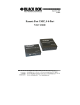
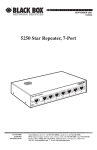
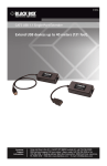
SEPTEMBER 2001
SWI080A
Network Power Switch Jr.
CUSTOMER SUPPORT INFORMATION
Order toll-free in the U.S.: Call 877-877-BBOX (outside U.S. call 724-746-5500)
FREE technical support 24 hours a day, 7 days a week: Call 724-746-5500 or fax 724-746-0746
Mailing address: Black Box Corporation, 1000 Park Drive, Lawrence, PA 15055-1018
Web site: www.blackbox.com • E-mail: [email protected]
FCC AND IC RFI STATEMENTS
FEDERAL COMMUNICATIONS COMMISSION
AND
INDUSTRY CANADA
RADIO FREQUENCY INTERFERENCE STATEMENTS
This equipment generates, uses, and can radiate radio frequency energy
and if not installed and used properly, that is, in strict accordance with the
manufacturer’s instructions, may cause interference to radio communication.
It has been tested and found to comply with the limits for a Class A computing
device in accordance with the specifications in Subpart J of Part 15 of FCC rules,
which are designed to provide reasonable protection against such interference
when the equipment is operated in a commercial environment. Operation of
this equipment in a residential area is likely to cause interference, in which case
the user at his own expense will be required to take whatever measures may be
necessary to correct the interference.
Changes or modifications not expressly approved by the party responsible
for compliance could void the user’s authority to operate the equipment.
This digital apparatus does not exceed the Class A limits for radio noise emission from
digital apparatus set out in the Radio Interference Regulation of Industry Canada.
Le présent appareil numérique n’émet pas de bruits radioélectriques dépassant les limites
applicables aux appareils numériques de classe A prescrites dans le Règlement sur le
brouillage radioélectrique publié par Industrie Canada.
1
NETWORK POWER SWITCH JR.
NORMAS OFICIALES MEXICANAS (NOM)
ELECTRICAL SAFETY STATEMENT
INSTRUCCIONES DE SEGURIDAD
1. Todas las instrucciones de seguridad y operación deberán ser leídas antes
de que el aparato eléctrico sea operado.
2. Las instrucciones de seguridad y operación deberán ser guardadas para
referencia futura.
3. Todas las advertencias en el aparato eléctrico y en sus instrucciones de
operación deben ser respetadas.
4. Todas las instrucciones de operación y uso deben ser seguidas.
5. El aparato eléctrico no deberá ser usado cerca del agua—por ejemplo,
cerca de la tina de baño, lavabo, sótano mojado o cerca de una alberca,
etc..
6. El aparato eléctrico debe ser usado únicamente con carritos o pedestales
que sean recomendados por el fabricante.
7. El aparato eléctrico debe ser montado a la pared o al techo sólo como sea
recomendado por el fabricante.
8. Servicio—El usuario no debe intentar dar servicio al equipo eléctrico más
allá a lo descrito en las instrucciones de operación. Todo otro servicio
deberá ser referido a personal de servicio calificado.
9. El aparato eléctrico debe ser situado de tal manera que su posición no
interfiera su uso. La colocación del aparato eléctrico sobre una cama,
sofá, alfombra o superficie similar puede bloquea la ventilación, no se
debe colocar en libreros o gabinetes que impidan el flujo de aire por los
orificios de ventilación.
2
NOM STATEMENT
10. El equipo eléctrico deber ser situado fuera del alcance de fuentes de calor
como radiadores, registros de calor, estufas u otros aparatos (incluyendo
amplificadores) que producen calor.
11. El aparato eléctrico deberá ser connectado a una fuente de poder sólo del
tipo descrito en el instructivo de operación, o como se indique en el
aparato.
12. Precaución debe ser tomada de tal manera que la tierra fisica y la
polarización del equipo no sea eliminada.
13. Los cables de la fuente de poder deben ser guiados de tal manera que no
sean pisados ni pellizcados por objetos colocados sobre o contra ellos,
poniendo particular atención a los contactos y receptáculos donde salen
del aparato.
14. El equipo eléctrico debe ser limpiado únicamente de acuerdo a las
recomendaciones del fabricante.
15. En caso de existir, una antena externa deberá ser localizada lejos de las
lineas de energia.
16. El cable de corriente deberá ser desconectado del cuando el equipo no
sea usado por un largo periodo de tiempo.
17. Cuidado debe ser tomado de tal manera que objectos liquidos no sean
derramados sobre la cubierta u orificios de ventilación.
18. Servicio por personal calificado deberá ser provisto cuando:
A:
El cable de poder o el contacto ha sido dañado; u
B:
Objectos han caído o líquido ha sido derramado dentro del
aparato; o
C:
El aparato ha sido expuesto a la lluvia; o
D:
El aparato parece no operar normalmente o muestra un cambio en
su desempeño; o
E:
El aparato ha sido tirado o su cubierta ha sido dañada.
3
NETWORK POWER SWITCH JR.
TRADEMARKS USED IN THIS MANUAL
Linux® is a registered trademark of Linus Torvalds.
UL® is a registered trademark of Underwriters
Laboratories Incorporated.
UNIX® is a registered trademark of UNIX System
Laboratories, Inc.
Windows® and Windows NT® are registered trademarks
of Microsoft Corporation.
Any other trademarks mentioned in this manual are
acknowledged to be the property of the trademark owners.
4
IMPORTANT SAFETY INFORMATION
IMPORTANT SAFETY INFORMATION
When using this product, follow these basic safety
precautions to reduce the risk of fire, electric shock, and
injury.
1. Read and understand all instructions.
2. Follow all warnings marked on the product.
3. Unplug this product from the wall outlet before
cleaning. Do not use liquid cleaners or aerosol
cleaners. Use a damp cloth for cleaning.
4. Do not use this product in an outdoor
environment or near water (for example, near a
bath tub, wash bowl, kitchen sink, or laundry tub,
in a wet basement, or near a swimming pool).
5. Do not place this product on an unstable cart,
stand, or table. The product may fall, causing
serious damage.
6. Slots and openings are provided for ventilation to
protect the product from overheating. These
openings should not be blocked or covered. The
openings should never be blocked by placing the
product on a bed, sofa, rug, or other similar
5
NETWORK POWER SWITCH JR.
surface. This product should never be placed in a
built-in installation unless proper ventilation is
provided.
7. This product should be operated only from the
type of power source indicated on the marking
label. If you are not sure of the type of power
supply to your home, consult your local power
company.
8. This product is equipped with a three-wire
grounding-type plug (a plug that has a third
[grounding] pin). This plug will only fit into a
grounding-type power outlet. This is a safety
feature. If you are unable to insert the plug into
the outlet, contact your electrician to replace your
obsolete outlet. Do not defeat the safety features
of the grounding-type plug by using a 3-to-2 prong
adapter at the receptacle. Using this type of
adapter may result in electrical shock and/or
damage to this product.
9. Do not allow anything to rest on the power cord.
Do not put this product where the cord will be
abused by persons walking on it.
10. Do not overload wall outlets and extension cords
as this can result in electric shock.
6
IMPORTANT SAFETY INFORMATION
11. Never push objects of any kind into this product
through slots, as they may touch dangerous
voltage points or short out parts that could result
in fire or electrical shock. Never spill liquid on the
product.
12. To reduce the risk of electrical shock, do not
disassemble this product; instead, take it to a
qualified service person when service or repair
work is required. Opening or removing covers may
expose you to dangerous voltages or other risks.
Incorrect re-assembly can cause electric shock
when the appliance is subsequently used.
13. Unplug this product from the wall outlet and refer
servicing to qualified service personnel under the
following conditions:
a. When the power supply cord or plug is
damaged or frayed.
b. If liquid has been spilled into the product.
c. If the product has been exposed to rain or
water.
d. If the product does not operate normally by
following the operating instructions. Adjust
7
NETWORK POWER SWITCH JR.
only those controls that are covered by the
operating instructions. Improper adjustment of
other controls may result in damage and will
often require extensive work by a qualified
technician to restore the product to normal
operation.
e. If the product has been dropped or has been
damaged.
f. If the product exhibits a distinct change in
performance.
14. Avoid using a telephone (other than a cordless
type) during a electrical storm. There may be a
remote risk of electric shock from lightning.
15. Do not use the telephone to report a gas leak in
the vicinity of the leak.
16. Do not exceed the maximum output rating of the
auxiliary power receptacle.
8
CONTENTS
Contents
Chapter
Page
1. Specifications. . . . . . . . . . . . . . . . . . . . . . . . . . . . . 11
2. Introduction . . . . . . . . . . . . . . . . . . . . . . . . . . . . . 12
2.1 Description . . . . . . . . . . . . . . . . . . . . . . . . . . . 12
2.2 Applications. . . . . . . . . . . . . . . . . . . . . . . . . . . 12
2.3 Auto-Ping . . . . . . . . . . . . . . . . . . . . . . . . . . . . . 13
2.3.1 Use Auto-Ping Locally . . . . . . . . . . . . . . . 14
2.3.2 Use Auto-Ping Remotely . . . . . . . . . . . . . 15
3. Hardware Installation . . . . . . . . . . . . . . . . . . . . . . 16
3.1 Power Connectors and Switches . . . . . . . . . . 16
3.2 Ethernet Connections. . . . . . . . . . . . . . . . . . . 17
3.3 AC Power Connections. . . . . . . . . . . . . . . . . . 18
4. Configuration . . . . . . . . . . . . . . . . . . . . . . . . . . . . 21
4.1 IP Address . . . . . . . . . . . . . . . . . . . . . . . . . . . . 21
4.1.1 Setting the IP Address Using a Web
Browser . . . . . . . . . . . . . . . . . . . . . . . . . . . 21
4.1.2 Setting the IP Address Using ARP. . . . . . 22
9
NETWORK POWER SWITCH JR.
Contents (continued)
Chapter
Page
4.2 Configuration Parameters . . . . . . . . . . . . . . . 23
4.2.1 Windows 3.11, 95, and Windows NT. . . . 23
4.2.2 Unix, Linux. . . . . . . . . . . . . . . . . . . . . . . . 24
5. Web Browser Operation . . . . . . . . . . . . . . . . . . . . 25
5.1 Password Protection . . . . . . . . . . . . . . . . . . . . 25
5.2 Main Screen. . . . . . . . . . . . . . . . . . . . . . . . . . . 26
5.3 Setup Page . . . . . . . . . . . . . . . . . . . . . . . . . . . . 27
6. User Settings . . . . . . . . . . . . . . . . . . . . . . . . . . . . . 28
7. Troubleshooting . . . . . . . . . . . . . . . . . . . . . . . . . . 29
7.1 Calling Black Box . . . . . . . . . . . . . . . . . . . . . . 29
7.2 Shipping and Packaging. . . . . . . . . . . . . . . . . 30
10
CHAPTER 1: Specifications
1. Specifications
Software Requirements: Netscape Navigator 3.0 or
higher; Internet Explorer 3.0 or higher
Capacity (Maximum): 12 amps @ 125 VAC; 10 amps
@ 240 VAC
Input Cord: 16 AWG x 3C 10A 250, UL®/CSA/VDE
Rated
Connectors: Power In: (1) IEC 320 male plug;
Power Out: (1) IEC 320 Receptacle; Network: (2) RJ-45
10/100BASE-T Ethernet
Power: 105–125/210–240 VAC, 50/60 Hz, switch
selectable
Size: 2.3"H x 4.5"W x 6"D (5.8 x 11.4 x 15.2 cm)
Weight: 1.3 lb. (0.6 kg)
11
NETWORK POWER SWITCH JR.
2. Introduction
2.1 Description
The Network Power Switch Jr. is a network-attached, IPaddressed, web-controlled AC power switch. Anyone
with a web browser can access the Switch for power on,
off, or reboot (timed power shutdown). The Switch is
password-protected for security. It also uses international
standard IEC 320 connections and is selectable for
115 VAC or 230 VAC. The Switch handles circuits up to
12 amps (10 amps at 230 VAC).
2.2 Applications
Uses for the Network Power Switch Jr. include:
• Remote reboot of any device, routers, servers,
kiosks, etc. The device to be rebooted need not be
attached to the network.
• Secure sensitive devices by keeping them powered
off when not in use. This prevents hackers from
seeing them at all times.
• Power down equipment when not needed for
power savings and to save on wear and tear.
12
CHAPTER 2: Introduction
• Power up alert devices such as sirens, lamps,
messages, or control environmental systems such
as heaters, coolers, pumps, etc.
Network Power
Switch Jr.
PC with
Web Browser
Internet or
Intranet
10/100
Ethernet
Figure 2-1. Typical application.
2.3 Auto-Ping
The Auto-Ping feature allows the Network Power Switch
Jr. to automatically detect failed equipment and perform
a timed reboot or other power control function (like
turning on an indicator or siren). You can set any IP
address to be periodically Pinged. When the Switch no
longer detects a response from the address, the
programmed power control function is actuated.
13
NETWORK POWER SWITCH JR.
2.3.1 USE AUTO-PING LOCALLY
Put the Network Power Switch Jr. next to the device to
be monitored and reboot the device automatically when
it no longer responds.
Ping
Response
Figure 2-2. Local ping: The Network Power Switch Jr. monitors the
local device and automatically reboots it if there is no response.
14
CHAPTER 2: Introduction
2.3.2 USE AUTO-PING REMOTELY
Put the Network Power Switch Jr. at a central facility to
monitor a remote system and power up an alert when
the remote device no longer responds.
Response
PC with
Web Browser
Network Power
Switch Jr.
Internet or
Intranet
Ping
10/100
Ethernet
Figure 2-3. Remote ping: The Network Power Switch Jr. monitors the
network connection and reboots when there is no response.
Response
Ping
Figure 2-4. Remote ping: The Network Power Switch Jr. monitors the
remote device and powers up an alarm when there is no response.
15
NETWORK POWER SWITCH JR.
3. Hardware Installation
3.1 Power Connectors and Switches
The diagrams below show the power connectors and
switches on the Network Power Switch Jr.
Figure 3-1. Power input, downlink, and uplink connectors.
Figure 3-2. Power input selector.
16
CHAPTER 3: Hardware Installation
Figure 3-3. Power output connector.
CAUTION
Make sure that the unit is set to the correct operating
voltage before plugging it in or applying AC power.
Disconnect the Network Power Switch Jr. from the AC
power source before making any control connections.
3.2 Ethernet Connections
The Network Power Switch Jr. supports 10/100 Ethernet
using CAT5 unshielded twisted-pair cabling. Uplink and
downlink connections are provided. Use the uplink jack
to connect to an Ethernet hub and the downlink jack to
connect to an additional piece of networking
equipment.
NOTE
An LED next to each connector indicates when the
connection to the network is properly established.
17
NETWORK POWER SWITCH JR.
Network Power
Switch Jr.
Networked device
(PC workstation, router, etc.)
10/100BASE-T unshielded
twisted pair
Network Hub or
Switch
Figure 3-4. Connections to Ethernet.
3.3 AC Power Connections
1. Select the input voltage (115 V for 110 to
125 VAC, 230 V for 215 to 240 VAC) before
making any connections.
Power Input
Selector
Figure 3-5. Selecting the input voltage.
18
CHAPTER 3: Hardware Installation
2. Connect to the power source. Use the included
cord for North America.
Figure 3-6. Connecting to the power source.
3. Connect the powered device. Use either an IEC to
NEMA extension cord (supplied) or an IEC to IEC
extension cord (not supplied).
Power
Controlled
Device
IEC to NEMA
extension cord
(supplied)
Figure 3-7. Connecting the powered device.
19
NETWORK POWER SWITCH JR.
You can set the Network Power Switch Jr. for operating
voltages of 110 to 120 VAC or 220 to 240 VAC via the
voltage selector switch located on the side of the unit.
CAUTION
Make sure that the voltage selector switch is set to the
correct position before applying power.
Connect the device to be powered ON and OFF to the
IEC receptacle marked “Switched Outlet.” A short IEC
320 to North American (NEMA 5-15) power cord is
included for connecting the Network Power Switch Jr.
outlet to the device to be power controlled. You can
connect the Switch to a power strip to simultaneously
control multiple devices.
CAUTION
Make sure that the combined load of all controlled devices
does not exceed 10 amps for 230 VAC or 12 amps for
115 VAC.
Connect the supplied power cord to the connector
labeled “AC Input,” and connect the other end to your
AC source. If a power cord with a different terminating
plug is required, be sure it is properly rated and meets
all required local electrical standards.
20
CHAPTER 4: Configuration
4. Configuration
4.1 IP Address
The Network Power Switch Jr. comes with a factoryinstalled IP address of 192.168.1.254. In most cases, you
will need to change this.
Consult your Network Administrator to determine the
appropriate IP address. You can set the IP address by
either using ARP or via a web browser. The Network
Power Switch Jr. does not support DHCP.
4.1.1 SETTING THE IP ADDRESS USING A WEB BROWSER
To set the IP address using the web browser, you must
reboot the Network Power Switch Jr. Do not use this
procedure from a remote location.
To set the IP address using a web browser, connect the
10/100BASE-T connection to your local Ethernet
network and apply power to the Network Power Switch
Jr.
Open your browser and access the Switch by entering
the default (192.168.1.254) or current IP address into
your browser’s Address window. Enter the password (the
21
NETWORK POWER SWITCH JR.
factory default is PASS). Click on Setup and enter the IP
address, subnet mask, and gateway address for your
network. Click Apply. Disconnect the power input to the
Switch. When you reconnect power, the new IP address
will be installed. See the web browser control for more
details and screen shots.
Changes to the subnet mask and gateway occur as soon
as you press the Apply button. You don’t have to powercycle the Switch.
4.1.2 SETTING THE IP ADDRESS USING ARP
The computer used to set the IP address must be on the
same local network segment as the Network Power
Switch Jr. ARP does not work across routed or switched
networks.
To set the IP address using ARP, you must know the
hardware (MAC) address. The address is printed on the
bottom of the Switch. The syntax for the MAC address is:
nn-nn-nn-nn-nn-nn.
22
CHAPTER 4: Configuration
4.2 Configuration Parameters
4.2.1 WINDOWS® 3.11, 95, AND WINDOWS NT®
1. Open a DOS window.
2. Type the following command:
arp -s <IP Address><MAC Address>
where <IP Address> is the desired IP address
(in dotted decimal notation) for the Network
Power Switch Jr. and <MAC Address> is the MAC
address of the Switch. The MAC address of the
Switch is printed on the bottom of the unit. If you
are using Windows 95, see the note below.
NOTE
Windows 95 users only: Due to a bug in the Windows 95
version of ARP, you must first have an empty ARP table
(seen with arp -a). To empty an arp table, type:
arp -d <ip address> for each entry in the arp table as
seen with arp -a. Ping an existing device on your network
before setting the IP address of the Switch. The device
must be a network device other than the one currently
being used.
23
NETWORK POWER SWITCH JR.
4.2.2 UNIX®, LINUX®
Consult your system administrator for information on
setting an IP address using ARP. You should ping the
unit after you set the IP address to confirm proper
operation.
24
CHAPTER 5: Web Browser Operation
5. Web Browser Operation
5.1 Password Protection
Open your browser and access the Network Power
Switch Jr. by entering the default (192.168.1.254) or
current IP address into your browser’s address window.
After connecting to the Switch, you’ll need a password.
You do not need a username.
The default password is PASS. You can change this from
the setup screen. Write down your password and keep it
in a secure place in case you forget it.
The Network Power Switch Jr. also uses an inactivity
timer for security. When there is no activity for 2
minutes, the connection is closed and you will need to
enter the password again for access.
25
NETWORK POWER SWITCH JR.
5.2 Main Screen
Once you enter the password, the following page
appears.
Figure 5-1. Set Location screen.
To control the power, click on the appropriate button.
During power cycling, the Power Status bar will indicate
the temporary status by using a blue background. Once
the cycle is complete, the status bar will revert to its
original condition. To abort a power cycle, click on
either the Power On or Power Off button. The Network
Power Switch Jr. will immediately assume the status
selected.
26
CHAPTER 5: Web Browser Operation
5.3 Setup Page
The setup page consists of four sections. Each time you
change a setting, click on Apply for that section to save
the changes in the Network Power Switch Jr. If you
change the IP address via this page, you must reboot the
Switch to install the new address. To do this, remove the
power cord on the Switch from its power source; don’t
just click on OFF from the main screen.
Figure 5-2. Setup page.
27
NETWORK POWER SWITCH JR.
6. User Settings
Record your Network Power Switch Jr.’s settings here.
MAC Address___________________________________
IP Address______________________________________
Subnet Mask____________________________________
Gateway________________________________________
Notes:
28
CHAPTER 7: Troubleshooting
7. Troubleshooting
7.1 Calling Black Box
If you determine that your Network Power Switch Jr. is
malfunctioning, do not attempt to alter or repair the
unit. It contains no user-serviceable parts. Contact Black
Box at 724-746-5500.
Before you do, make a record of the history of the
problem. We will be able to provide more efficient and
accurate assistance if you have a complete description,
including:
• the nature and duration of the problem.
• when the problem occurs.
• the components involved in the problem.
• any particular application that, when used,
appears to create the problem or make it worse.
29
NETWORK POWER SWITCH JR.
7.2 Shipping and Packaging
If you need to transport or ship your Network Power
Switch Jr.:
• Package it carefully. We recommend that you use
the original container.
• If you are shipping the Network Power Switch Jr.
for repair, make sure you include everything that
came in the original package. Before you ship,
contact Black Box to get a Return Authorization
(RA) number.
30
© Copyright 2002. Black Box Corporation. All rights reserved.
1000 Park Drive
•
Lawrence, PA 15055-1018
•
724-746-5500
•
Fax 724-746-0746