1
INSTRUCTlONS/PARTS LIST
307-830
ORACO
Rev A
This manual contains IMPORTANT
WARNINGS and INSTRUCTIONS
READ AND RETAIN FORREFERENCE
EM590"AlRLESS PAINT SPRAYER
25w psi 1175 bar) MAXIMUM WORKING PRESSURE
220-856.
Model
Series A
Basic Sprayer without hose or gun
Model 231-590
Same as 220-586and includes 50 ft (15.1 m) hose,
3 ft (0.9m) whip hose, and spray gun with
RAC IV DripLess" Tip Guardand
517 size SwitchTipTM
INDEX
....................................
..............................
................................
........................................
.....................
.........................................
Warnings
2
Avertissement
4
Advertencia
.6
Terms
8
Sprayer Components
a
Setup
9
Operation ..................................
10
.11
Shutdown Et Care .......................
Flushing Guidelines ......................
12
.................... 13
Methods
Application
Troubleshooting Guide
14
Repair Section
Bearing Housing 8
..................... 16
RodConnecting
Housing
Drive
17
Motor
18
Pressure Control
20
Calibration
22
Parts List Et Drawings
Pressure Control
23
Sprayer
;..24
How To Order Replacement
Parts.
Repair Kits
Technical Data
Back Co
Warranty
.Back Co
.................
..........................
....................................
......................
..............................
......................
...............................
...................................
.............................
................
......................
WARNING
:
Hazard of Using Fluids Containing Halogenated Hydrocarbons
Never use 1.1.1-trichloroethane, methylene chloride, other halogenated hydrocarbon solvents or fluids containing
such solvents in this equipment. Such
use could result ina serious chemical reaction, with the possibilityof explosion, which could cause death, serious bodily injury and/or substantial property damage.
Consult your fluid suppliers to ensure that the fluids being used are compatible with aluminum andzinc parts.
GRACO INC. P.O. Box 1441 MINNEAPOLIS, M N 554404444
@COPYRIGHT 1987GRACO INC.
WARNlNG
~
I
:
HIGH PRESSURE SPRAY CAN CAUSE SERIOUS INJURY.
FOR PROFESSIONAL USE ONLY. OBSERVE ALL WARNINGS.
Read and understand all instruction manuals before operating equipment.
FLUID INJECTION HAZARD
General Safety
. .
This equipment generates very
hqh fluid pressure. Sprayfrom
thegun,leaks
or rupturedcomponentscaninject
fluid
through your skin and into your body and cause extremely
serious bodily injury, includingthe need for amputation. Also,
fluid injectedorsplashed into the evesor on the skincan
cause serious damage,
NEVER point the spray gun at anyone or at any part of the
body. NEVER put hand or fingers over the spray tip. NEVER
try to "blow back" paint; this is NOT an air spray system.
ALWAYS have the tip guard in place on the spray gun when
spraying.
ALWAYS follow the Pressure Relief Procedure.below.
before cleaning or removing the spray
tip or servicing a n i
system equipment.
NEVER try to stop or deflect leaks with your hand or body.
Be sureequipmentsafetydevicesareoperatingproperly
before each use.
Medical Alert-Airless Spray Wounds
If any fluid appears to penetrate your skin, get EMERGENCY
MEDICAL CARE AT ONCE. DO NOT TREAT AS A
SIMPLE CUT. Tell the doctor exactly whatfluid was injected.
Note to Physlclan: Injection in the skin is a traumatic injury. It Is Important t o treat the injury surgically
as soon
ea possible. Do not delay treatment to research toxic!?y.
Toxicily is a concern with some exotic coatings injected
direct& into the blood stream. Consultation with a plastic
surgeon or reconstructive hand surgaon maybe advisable.
..i::. . ,:..
...
.... . . ..
,
Spray Gun Safety Devices
Be sure all gun safety devices are operating properly before
each use. Do not remove or modify any part of the gun; this
can cause a malfunction and result in serious bodily-injury
Safety Latch
Whenever you stop spraying, even for a moment, always set
the gun safety latch in the closed or "safe" position, making
in
the gun inoperative. Failureto set the safety latch can result
accidental triggering of the gun.
Diffuser
The gun diffuser breaksup spray and reducesthe risk of fluid
injection whenthe tip is not installed. Check diffuser operation
regularly.FollowthePressure
Relief Procedure,below,
thenremove the spray tip. Aim the gun into ametalpail,
holding the gun firmly to the pail. Using the lowest possible
pressure, trigger the gun.If the fluid emittedis notdiffused into an irregular stream, replace the diffuser immediately.
Tip Guard
ALWAYS have the tip guard in place on the spray gun while
spraying. Thetip guard alerts youto the fluid injection hazard
and helos reduce.but does not orevent. the risk of accidentally placing your fingers or any pan of iour body close to the
spray tip.
Trigger Guard
Always havethe trigger guardin place on the gun when spraying to reduce the risk of accidentally triggering the gunif it is
dropped or bumped.
Spray Tip Safety
U s e extreme caution when cleaningor changing spray tips.If
the spraytip clogs while spraying, engage
the gun safety latch
immediately.ALWAYS follow the Pressure Relief Procedure and then removethe spray tip to clean it.
NEVER wipe off build-up aroundthe spray tip until pressure is
fully relieved and the gun safety latch is engaged.
,..
.
Pressure Relief Procedure
To reduce the risk of serious bodily injury, includingfluid iniection, splashingfluid or solventin the eves or on the skin, or iniurv
from moving partsor electric shock, alwaysfollowthis procedure wheneveryou shutoff the sprayer, when checkingor sekicor changing spray tips, and whenever you stop spraying.
(11 Engage
ing any part of the spray system, when installing, cleaning
(4) Disengage thegun safety latch.
the gun safety latch.(21Turn the ON/OFF switch to OFF. (3) Unplug the power supply cord.
(51 Hold a metal
part of the gun firmlyto the side of a grounded metal pail, and trigger the
to gun
relieve pressure.(61 Engagethe
gun safety latch. (7) Open the prmure relief valve, having a container ready
to catch the drainage. (81 Leave the pressure relief
valve open until you are ready to spray again.
..
If you suspect that the spraytip or hose is completely clogged, or that pressure hasnot been ful& relieved after following the
tip guard retainingnut or hose end coupling and relieve pressure gradually, then loosen
stepsabove. VERY SLOWLY loosen the
eompletely. Now clear the tip or hose.
II
, .
..
~. . .
2
307-830
EQUIPMENT MISUSE HAZARD
FIRE OR EXPLOSION HAZARD
General Safety
Any misuse of the spray equipment or accessories, such
as
overpressurizing, modifying parts, using incompatible
chemicals and fluids, or using worn or damaged parts, can
cause themto rupture and resultin fluid iniection, splashingin
the eyes or on the skin, or other serious bodily injury, fire, explosion or properly damage.
Static electricity is created by the high velocity flow of fluid
through the pump and hose. If every part of the spray equipment is not properly grounded, sparking may occur, and the
systemmaybecomehazardous.Sparkingmayalsooccur
when plugging in or unplugging a power supply cord. Sparks
can ignite fumes from solvents and the fluid being sprayed,
dust particles and other flammable substances, whether you
are spraying indoors or outdoors, and can cause a fire or explosionandseriousbodilyinjuryandpropertydamage.
Always plug the sprayer into an outlet at least 20 feet 16 m)
away from the sprayer and the spray area. Do not plug in or
unplug, any power supply cords
in the spray areawhen there is
any chance of igniting fumes still in the air.
NEVER alter or modify any part of this equipment; doing so
could cause it to malfunction.
CHECK all sprayequipmentregularlyandrepair
worn or damaged parts immediately.
or replace
Alwayswearprotectiveeyewear,glovesandclothingas
recommended by the fluid and Solvent manufacturer.
System Pressure
Thissprayercandevelop
25W psi 1175 bar) MAXIMUM
WORKING PRESSURE. Be sure that all spray equipment and
accessoriesarerated
to withstand the maximumworking
pressure of this sprayer. DO NOT exceed the maximum workingpressureofanycomponentoraccessoryused
in the
system.
Fluid a n d Solvent Compatibility
BE SURE that all fluids and solvents used
are chemically compatible with the wetted parts shownin the Technical Data on
the back cover. Always read the fiuid and solvent manufacturer's literature before using themin this sprayer.
HOSE SAFETY
High pressurefluid in the hoses can be very dangerous,If the
hose develops a leak,split or rupture dueto any kindof wear,
it can
damage or misuse, the
high pressure spray emitted from
cause a fluid injection injury or other serious bodily injury or
property damage.
ALL FLUID HOSES MUST HAVE SPRING GUARDS ON
BOTH ENDS1 The spring guards help protectthe hose from
kinks or bendsat or close to the coupling which can resultin
hose rupture.
TIGHTEN all fluid connections securely before each use. High
pressure fluid candislodgea loose couplingorallow high
pressure spray to be emitted from the coupling.
NEVER use a damaged hose. Before each use, check the entire hose for cuts, leaks, abrasion, bulging cover,
or damage or
movement of the hose couplings. If any of these conditions
exist. replace the hose immediately. DO NOT try to recouple
it with tape or any other device. A
high pressure hose or mend
repaired hose cannot contain the high pressure fluid.
HANDLE AND ROUTE HOSES CAREFULLY.Do not pull on
hoses to move equipment.Do not use fluids or solvents which
are not compatible with the inner tube and cover
of the hose.
DO NOTexposeGracohose
to temperaturesabove 1 W "
(82"CI or below -40°F (-40°C).
Hose Grounding Continuity
Proper hose grounding continuity is essential
to maintaining a
grounded spray system. Check theelectrical resistance of your
fluid hoses at least once a week.If your hose doesnot have a
tag on it which specifies the maximum electrical resistance,
contact the hose supplier or manufacturer for the maximum
resistance limits. Use a resistance meter in the appropriate
range for your hose to check the resistance. If the resistance
exceeds the recommended limits, replace it immediately. An
ungrounded or poorly grounded hose can make your system
hazardous. Also read FIRE OR EXPLOSION HAZARD.
If you experience any static sparking or even a slight shock
whileusingthisequipment,STOP
SPRAYING IMMEDIATELY. Checkthe entire systemfor DroDer aroundina. Do not
use the System againuntil the Droblem has been ideniified and
corrected.
Grounding
To reduce the risk of static sparking, ground the sprayer and
all other spray equipment used or located in the spray area.
CHECK your local electrical code for detailed grounding instructions for your area and type of equipment. BE SURE to
ground a11 of this spray equipment:
1.Sprayer:
plug the power supply cord, or extension cord,
each equippedwith an undamaged three-prong plug,
into
a properly grounded outlet.
Do not use an adapter.All extension cords must have three wires and be rated
for 15
amps.
2.
Fluidhoses: use only grounded hoseswith a maximum of
500feet 1150 ml combined hoselengthto ensuregrounding continuity. Refer to Hose Grounding Continuity.
3.
Spray gun: obtaingroundingthroughconnection
properly grounded fluid hose and sprayer.
to a
4.
Object being sprayed: according to local code.
5.
Fluidsupply container: according to local code.
6.
All solvent pails used when flushing, according
7.
To maintain grounding continuity when flushingorrelievingpressure, always hold a metal part of the gun
firmly to
the side of a groundedmetal pail, then triggerthe gun.
to local
code. Use only metalpails, which are conductive.Do not
place the pailon a non-conductive surface, suchas paper
or cardboard, which interrupts the grounding continuity.
Flushing Safety
Reduce the risk of fluid injection injury, static sparking, or
splashing by following the specific flushing procedure given
on page 12 of this manual. Follow the Pressure Relief Procedure on page 4, and remove the spraytip before flushing.
Hold a metal part ofthe gun firmly to the side of a metal pail
and use the lowest possible fluid pressure during flushing.
MOVING PARTS HAZARD
Movingpartscanpinch
or amputate your fingers or other
body parts. KEEPCLEAR of moving parts when starting or
operating the sprayer.Unplug the sprayer,and follow the
Pressure Relief Procedure on page 2. before checking or
servicing any part of the sprayer to prevent it from starting
accidentally.
IMPORTANT
United States Government safety standards have been adopted under the Occupational Safety and Health Act. These standards-par
ticularly the General Standards, Part 1910, and the Construction Standards, Part 1926-should be consulted.
307830
3
La pulvbrisation B haute pression peut causer des blessures tr8s graves.
Rhservh exclusivement A I'usage professionnel. Observer toutes les consignes de s6curit6.
Bien lire et bien comprendre tous les manuels d'instructions avant d'utiliser le mathriel.
RlSQUES D'INJECTION
Consignes gbnerales de skurite
Cet appareil produit un fluide B t r b haute pression. Le fluide
pulverise parle pistolet ou le fluide sous pression provenant de
B I'inthrieur
fuites ou de ruptures peut penetrer sous la ou
peau
meme une
du corpset entrainer des blessures trbs graves, voir
le fluide Bclabousamputation. MBme sans &re sous pression,
sant ou entrantdans
18s yeux peutaussientrainerdes
Messures graves.
NE JAMAIS pointer le pistolat vers quelqu'unou vers une partie quelconque du corps. NE JAMAIS menre la main ou ies
doigts sur i'ajutage du pulvhrisateur. NE JAMAIS essayer de
"refouler" la peintura. Cet appareil N'est PAS un compresseur
pneumatique.
TOUJOURS garder la protection de I'ajutage en place sur le
pistolet pendant la pulvBrisation.
TOUJOURS observer la March B Suivre pour DBtendre la
Pression donnee DIUS
loin. avant de nettover
. ou d'enlever
l'ajutage du pulvbrisateur, ou d'effectuer un travail quelconque sur une partie de I'appareil:
NE JAMAIS @sayer
d'arrhter ou de dbvier les fuites avec la
main ou le corm.
Avant chaque utilisation, bien s'assurer que les dispositifs de
securite fonctionnent corractement.
Soins medicaux
Encasde oenetration de fluide sous la oeau: nFMaNnFn
IMMEDIATEMENT
D E S ~ ~ O I N MEDICAUX
S
D'URGENCE.
NE
PAS SOIGNER CEITE BLESSURE
COMME UNE SIMPLECOUPURE.
Avls au medecin: La pdndtration des Nuides sous la peau
est . un traumatisme. II est Importantdetralter
chirurgicalement cene blessureimmbdiatement.Na
pas retarder le traitemenr pour effectuer des recherches sur
la toxicitd. Certains rev6tement.s exotiques
sont dangereusement toxiques w a n d ils sont injectds directement dans le
sang. I1 est souhairablede consulter un chirurgien esthdtique
ou un chirurgien spdcialis.4 dansla raconstruction des mains.
Dispositifs d e securite du pistolet
Avant chaque utilisation, biens'assure que tous Ies dispositifs
des6curitB du pistoletfonctionnentcorrectement.Nepas
~~
~~
~~~~~
"...
I.."_..
enlever ni modifier une partie quelconque du pistolet; ceci risquarait
d'entrainer
un
mauvais
fonctionnement
et des
blessures graves.
Verrou de sdcurit.4
A chaque fois que I'on s'arrste de pulvbriser, meme s'il s'agit
d'un court instant, toujours menre le verrou de s6curitB du
pistolet sur la position "ferm6e" ou "sbcurit8" ("safe") pour
empecher le pistolet de fonctionner. Si le verrou de sBcurit6
n'est pas mis, le pistolet peutse deciencher accidentellement.
Voir la Fig. 3.
Diffuser
Le diffuseur du pistolet sen B diviser le jet et B rbduire les risquesd'injectionaccidentellequandI'ajutagen'estpasen
place. Verifier le fonctionnement du diffuseur r6guli8remenl.
Pour cette v6rification. detendre la pression en observant la
Marche B Suivre pour DBtendre la Pression donnda plus
loin puis enlever I'ajutage du pulvbrisateur. Pointer le pistolet
dans un seau en metal, en le maintenant fermement contrele
seam Puis, en utilisant la pression la plus faible possible, appuyer sur la gachenedu pistolet. Si le fluide projete n'estpas
diffuse sous forme de jet irrbgulier, remplacer immBdiatement
le diffuseur.
Protection deI'ajutage
TOUJOURS maintenir la protection de I'aiutaaedace
en sur ie
pistolet du pulverisateur pendant la pulv&is<tion.'La protection de I'ajutage attire l'attention sur les risques d'injection
et
contribue B reduire, mais n'bvite pas le risque, que Ies doigts
ou une partie quelconque du corps ne passent accidentellement A proximite immediate de I'ajutagedu pulv6risateur.
du
Consignesde sbcuritb concernantI'ajutage
pulvhsateur
Faire extrSmement attention B I'occasion du nettoyage ou du
remplacement des ajutages du pulv8risateur. Si I'ajutage se
bouchependant la pulvbrisation,menreimmbdiatement
le
verrou de skurite du pistolet. TOUJOURS bien observer la
Marche Suivre pour DBtendre la Pression puis enlever
I'ajutage du pulvBrisateur pour le nenoyer.
NE JAMAIS essuyer ce qui s'est accumulB autour de i'ajutage
du pulvbrisateur avant que la pression ne soit completement
tombee et que le verrou de sBcurit6
du pistolet ne soit engage.
Marche B Suivre pour DBtendre la Pression
Pourreduire 1 % risquesdeblessuresgraves,
y compris les blessuresparinjectiondefluide
ou cellescausBespardes
Bclaboussures dansIes yeux ou sur la peau, des pieces enmouvement ou par Blectrocution, toujours bien observer cette marche
B suivre A chaque fois que l'on arretele pulvbrisateur, B l'occasion de la verification
ou de la reparation d'une piece de i'appareil
de pulv6risation. A l'occasion de I'installation, du nettoyage ou du remplacement des ajutageset d'une maniere g6nBraleA chaARRET ("OFF"). 3) DBbrancher
que arret. 1t Engager le verrou deskurite du pistolet.21 Menre I'interrupteur Marche-Arr6t sur
le cordon d'alimentation. 4) Dkengager le verrou de skurit6 du pistolet. 5) En maintenant une partie metallique du pistolet
fermement appuy4e contrele c8t6 dun seau en mbtal, appuyer surla gachette du pistolet pourIibBrer la pression.6) Engager le
verrou de securit6 du pistolet. 7) Ouvrir la soupape de sBcurite en prenant soin d'avoir
un recipient pr&tB recuperer le liquide.
81 hisser la soupape ouverte jusqu'h ce que le pulvbrisateur soit de nouveau pret B &re utilisB.
SiI'on soupconna queI'ajutage do pulvdrisateur ou le tuvau esr compl&ement bouchd,ou que la pression n'spas dtd compldtement libdrh apr& avoir procddd aux op.4rations ci-dessus, desserrar TRES LENTEMENT I'Bcrou de retenueprotection
de la
de
tuyau at liberer progressivement la pression, puis terminer
le desserrage. On peut maifitenant
I'ajutage oule raccord du bout du
debaucher I'ajutage ou le tuyau.
. .
1
307-830
-
2
3
4.5.6
7
.,
..
.. . .
RISQUES EN CAS DE MAUVAISE UTILISATION DU MATERIEL
Consignes gh6rales de s6curit6
Pression
Toute utilisation anormale de
I'appareil de pulverisation ou des
Ce pulverisateur peut produire un PRESSION
MAXIMUM DE
accessoires comme, par exemple, la mise sous une pression
TRAVAIL 175 bar /25w lb/po. 1. S'assurer que tous les
excessive,Ies modifications de pikes, I'utilisation de produits Bl4ments
du pulvbrisateur et ses accessoires sont concus pour
B lapressionmaximumdetravaildecepulvdrisateur.
chimiques et dematibresincompatibles
et l'utilisation deresister
NE PAS dbpasser la pression maximum de travail d'aucun des
pieces us6es ou abimees peut causer des d6gAts B I'appareil ou
Blhents ouaccessoires utilisk avec cet appareil.
des ruptures de pieces et entrainer une injection de liquide ou
Compatibilit6 des corps
d'autres
blessures
sdrieuses,
incendie,
un une
explosion
ou
d'autres d4gAts.
MENS'ASSURER que tous Ies corps dessolvants utilisbs
sont chimiquement compatibles avec Ies parties mouill6esinNE JAMAIS alterer ou modifier unep i k e de cet appareil; ceci
diqu6es dans les "Donnbes techniques". au dos de la couverrisquerait d'entrainer son mauvais fonctionnement.
ture.
Touiours
soigneusement
les documents
et Sl
brochures
VERIFIER rhgulierementtout I'appareildepulverisation et SBS
du fabricant
deslire
fluides
et
UtiliSk
avant de
en seNir
bquipements
et
reparer
ou remplacer
immediatement
les
dans ce pulv6risateur,
pieces us& ou abimbes.
3
MESURES DE SECURITE CONCERNANT LES TUYAUX FLEXIBLES
Le fluide B haute pression circulant dans Ies tuyaux peut Atre par
tout autre moyen. Un tuyau repare ne peut pas resister au
Ruide sous pression.
trbs dangereux.Encasde
fuite sur le tuyau,defissure,
dbchirure ou rupture B la suite de I'usure, de dbgstsou d'une
MANIPULER
LES
TUVAUX AVEC
PRECAUTION
ET
mauvaise utilisation. les projections
de
fluide
haute
pression
C H ~ lS
~~
lR
l ~ N ~ ~ ~ E M ECHEMIN,
N T
Nepasdbplacer
qui en proviennent peuvent entrainer
des blessures graves par
lefluide en
sur letuyau. N~ pas UtiliSer
defluides ou de
penetration sousla peau ou par contact, ainsi que des degas
qui ne
pas compatibles avec l'enVeloppe
inmat6riels.
terieure ou extkieure du tuyau. NE PAS exposer le tuyau B
TOUSLES TUYAUX FLEXIBLES DOIVENT AVOlR DESdestemperaturessuperieures
B 82OC 1180°Fl ouinferieures B
RESSORTS SPIRALE DE PROTECTION AUX 2 BOUTSl
- 4 O O C 1-4O"FI.
Continuite de la mise
la terre des tu aux
Lesspiralesde protectioncontribuent B bviterlaformationde
.... . . ..
. .. . .
pliures.deboucles ou'de nceudssurlestuyauxquipourraientUne
benne continuite
de la miSe
a la terre Jes tuyaux est
..
entrainerlarupturedutuyau
B I'endroitduraccordou
B son
eSSentielle
pour maintenir
la mise terre deI'ensemblede
deBlectrique
resistance la vaporisation.
VBrifiez
voisinage.
B
fluides et B air, au rnoins une fois par semaine. Si votre tuyau
SERRER FERMEMENT tous les raccords avant chaqueutilisane comporte pas d'dtiquene qui precise la resistance Blectrition. Le fluide sous pressionpeutfairesauterunraccord
desserre ou produire un jet B haute pression s'bchappant par le que maximum, prenez contact avec le fournisseur de tuyaux
ou la fabricant pour avoir Ies limites de resistance maximum.
raccord.
NE JAMAIS utiliSer un tUvaU endommage, Avant chaque
Utilisezunmhtrederesistancede
la gammeappropribepour
votre
tuyauet vbrifiez la resistance.Situyau
celle-ci
depasse
Ies
limites recommandees,
immaiatement,
utilisation.
verifier
entierernent
chaque
tuyau
pour
deceler
les
coupures,
fuites,
abrasions,
boursouflures
de
I'enveloppe
ou
autre
ou ieu des raccords. si I.0n constate
Un tuyau sansmise B la terre ou avecunemise B laterreincorI'une de ces deteriorations, il
tuyau im.
r e m peut
entrainer
risques
desPour
Votre
systhme.
aussiLES RISQUES D'INCENDIE OU D'EXPLOSIONcimbdiatement. NE PAS essayer de refaire le raccord d'un tuyau
dessus.
ou
haute pressionni de reparer le tuyau avec du ruban adhesif
~. .
,.
.
.I
.,. . ,.~
..
. .. .
..
RISQUES D'INCENDIE OU D'EXPLOSION
2. Tuyaux flexibles: Afin d'assurer la continuit6 de la miseA la
B la terre
terre, n'utiliser que des tuyaux comportant une mise
et avant
une
longueur
maximum
combinhe
de
150 m
11500 pieds).Sereporterdgalemerit
au paragraphe"Continuit6 du circuit de mise
A la terre des tuyeux".
3. Pistolet:Rbaliserlamise B la terre en le raccordant B un
tuyau flexibleet B un pulverisateur deja convenablement relies
B la terre.
4. Recipient d'alimentation: observer le code ou Ies reglementations locales.
5. Objets, matdriel ou sutfacesrecevant la pulvdrisation:
Observer le code ou Ies reglementations locales.
6. Tousles seaux de solvants utilisbs pour le rincage: observer
le codeou 18s reglementations locales.Nutiliser que des seaux
mdtalliques conducteurs de I'Wectricite. Ne pas menre le seau
sur une surface non conductrice comme sur du papier ou du
carton car cela interromprait la continuit6 le la mise B la terre.
7. Pour conserver la continuit6 de la mise B la terre wand on
rinca le matdriel ou quand on lib.4re la prassion,toujours
maintenir une partie metallique
du pistolet fermement appuyee
contre le cere d'un seau enmdtal puis appuyer sur la detente
du pistolet.
Mise B la terre ou B la masse
Mesures de SBcurit6 concernant le Rincage
Pour rbduire les risques de production d'6tincelles d'blectricitb
PourrbduireIesrisquesdeblessurespar.penetrationde
la
statique, le pulvbrisateuret tous les Bquipements utills6s ou se
peau et Ies risques dils aux btincelles d'6lenricit6 statique ou
trouvant dans la zone de pulverisation doivent &re relies B la
B suivre pourle rincage
tene ouB la masse. Pour connaitre le detail des instructions de aux klaboussures, observer la marche
donnbe B la page 12 de ce manuel. Observer la "Marche A
mise B la terre dans la region et le type particulier d'hquipeSuivre pour DBtendre la Pression" don& B la page 4 en
ment, CONSULTER le code
ou les r6glementations Blectriques
enlaver llajutage du pulv6risateur avant le rincage. Maintenir
locales. S'ASSURER que tous Ies Bquipements de pulvbrisaune partie mbtallique du pistolet fermement appuyee contre le
tion suivants sont bien reliesB la terre:
cat6 d'unseauen metal et utiliser la pression la plus faible
1. Pulvdrisateur:Erancherlecordond'alimentation
ou la
possible pendant le rincage.
rallonge qui doivent &re Bquipbs d'une priseB 3 fiches en bon
&at,dansuneprisedecourantconvenablementmise
A la
terre. Ne pas utiliser d'adaptateur. Toutes
Ies rallonges doivent
avoir 3 fils et Atre pr&ues pour 15 ampbres.
307-830 5
De I'blectricit6 statique est produite par le passage du fluide
B
grande vitesse dans la pompe et dans les tuyaux. Si toutes
Ies
pikes de I'appareil de pulverisation ne sont pas convenablement relieesB la masse ou B la terre, des Btincelles peuvent se
produire et I'appareil risque d'6tre dangereux. Des Btincelles
peuvent 6galement se pioduire B I'occasion du branchement
ou du dbbranchernent du cordon d'alimentation. Les btincelles
sont suffisantes pour allumer les 'vapeurs de solvants et
le
fluidepulvdrisb,lesfinesparticulesdepoussibreainsique
d'autres substances inflammables, quand on pulvbrise B fintbrieur ou B I'exterieur, et elles peuvent causer un incendieou
une explosion, ainsi que des blessures graves et des dbgPts
materiels. Toujours brancher le pulvbrisateur dans une prise
se
trouvant B au moins6 m 1 2 0 pieds) de I'appareil et de I'endroit
oh se fait la pulvbrisation. Ne pas brancher ou dbbrancher un
cordon d'alimentation que1 qu'il soit dans la zone o i se fait la
pulvbrisation quand il y a le moindre risque que des vapeurs
encore presentes dansYair prennent feu.
S'il se produit des Btincelles dYlectricit6 statique, ou si vous
ressentez la moindre dkharge, ARRETE2 IMMEDIATEMENT
LA PULVERISATION. Vbrifiez que le systhe entier est bien
mis B la terre. Ne vous servez pas
du systeme avant que
le prob l b e soit identifib et corrigb.
.>,, ,
-
. . .. . ...
ADVERTENCIA
EL ROCIADO A ALTA PRESION PUEDE CAUSAR GRAVES LESIONES.
SOLO PARA US0 PROFESIONAL. RESPETE LOS AVISOS DE ADVERTENCIA.
Lea y entienda todo el manual de instrucciones antes de rnanejar el equipo.
PELIGRO DE INYECCION DE FLUID0
.:
.:
. .,.. .
I
..... ...,,. ...
.~.:
.
..,,
Seguridad general
Aparatos de seguridad de la pistola pulverizadora
Este equ~pogenera unfluidoaunapresi6n
muy aka. El
Asegurarquetodos 10s aparatosprotectoresdelapistola
rociado de la pistola, 10s escapes de fluido o roturas de 10s
estdn funcionandobienantesdecada
uso. No sacar ni
componentes pueden inyectar.fluido en la piel y el cuerpo y
modificar ninguna pieza de la pistola pues podria causar
el
causar lesiones extremadamente graves, incluyendo a veces la malfuncionamiento de la mismacon las consiguientes lesiones
el fluido inyectado o
necesidaddeamputaci6n.Tambibn,
personales.
salpicado en 10s oios puede causar graves daaos.
Pestillo'de seguridad
NUNCA apuntar la pistola hacia alguien
o alguna parte del
Cada vez que se deje de pulverizar, aunque sea por un breve
cuerpo. NUNCA colocarla mano o 10s dedos encima de la boel pestillo deseguridad en la
momento.siemprecolocar
quilla. NUNCA tratar de "hacer retornar la pintura"; este NO
posici6n"cerrada". lo que deja la pistola inoperante. El no
es un sistema de rociado de aire.
hacerlo puede llevar al disparo imprevisto de la pistola.
SIEMPREtenercolocado el protectordelaboquillaenla
Difusor
pistola mientras se esth pulverizando.
El difusor de la pistola dispersael chorro pulverizado y reduce
el riesgo de inyecci6n cuando no esth instalada la boquilla.
SIEMPRE seguire1 procedimiento dedescarga depresi6n.
Revisar con regularidad e1 funcionamiento del difusor. Seguir
dado mhs abjo, antes de limpiar o sacar la boquilla o de dar
el procedimiento dedescarga d e p r e s h dado
.
mds abajo.
servicio a cualiquier equipo del sistema.
y despu6ssacarlaboquilla.Apuntarlapistolaa
unbalde
NUNCA tratar de pararo desviar 10s escapes con la manoo el
methlico,sosteni6ndolabien
firme contra 4 . Utilizando la
cuerpo.
la pistola.Si el fluido
presi6n mds bajoposible,disparar
emitido no sale disperso en un chorro irregular, reemplazar de
Asegurarquetodos
10s aparatosdeseguridaddelequipo
inmediato el difusor.
e s t h funcionando bien antes decada uso.
Protector de la boquilla
Tratamiento medico
SIEMPREtener el protectordelaboquillacolocadoenla
Si pareciera que un poco de fluido penetr6 la piel, conseguir
pistola mientras se esth pulverizando. Este protector llama la
TRATAMIENTO
MEDICO
DE URGENCIA
DE
INatenci6n contrae1 peligro de inyecci6ny ayuda a reducir. pero
MEOIATO. NO TRATAR LA HERIOA COMO UN SIMPLE
no evita,la colocaci6n accidental de10s dedos o cualquier otra
CORTE. Decir a1 mklico exactamente cua fluido fue.
parte del cuerpo cerca de la boquilla.
A vis0 ai medico: Si se llega a inyecter este fluido laen
pie/
Seguridad de la boquilla pulverizadora
se causaunalesidntraumdtica.
Es Imponantetretar
Tener mucho cuidado al limpiar
o cambiar las boquillas. Si
quirGrgicamente le lesi6n e le brevedadposible. No
llegara a obstruirse mientras estd pulverizando, enganchar el
demorar el tratamiento para investigar la toxicidad. La toxel propestillo dela pistoladeinmediato.SIEMPREseguir
icidad es algodesumaimportancia
en algunaspinturas
cedimiento de descarga de presi6n y despuk sacar la boexdticas
cuando
se inyectan directamente a1 torrente
quilla para limpiarla.
sanguineo. Sird conveniente consu/tar a un especialista en
ciwgia pldstica o reconstructiva de /as manos.
la boNUNCA limpiar la acumulaci6n de pintura alrededor de
se hayadescargadoporcompletola
quillaantesdeque
presi6n y el pestillo est6 enganchado.
Procedimiento de descarga de presi6n
o lesiones causadas por piezas en movimiento
0
Para reducir el riesgo desufrir graves lesiones corporales, incluyendo inyeccibn
choque elbctrico, siempre seguir este procedimiento al apagar
la mdquina pulverizadora, al revisar
o dar servicioa cualquier parte
del sistema de pulverizaci6n.a1 instalar, limpiar 0 cambiar las boquillas, y cada vez que se deja de pulverizar. (1) Enganchar e1
pestillo de la pistola. (2) Mover el interruptor electric0 (ON/OFF) a la posicibn OFF (apagadol.
(3) Desenchufar el cordbn
el6ctrico. (4) Desenganchar el pestillo de la pistola. (5) Sujetar una parte methlica de la pistola bien firme contra un balde de
(61 Enganchar el pestillo de la pistola. (7) Abrir la vhlvula de pr6sion
y tener
metal, y disparar la pistola para descargar la presi6n.
(8) Dejar la vdlvula dealivio de prkion abierta hasta quese est6 nuevamentelist0 para
listo un reclipiente para recibir la pintura.
pulverizar.
Sise sospecha que la boquilla
o la manguera estd completamente obstruida,o que no se ha descargado por completo
/a presidn
despuds de haber seguido elprocedimiento anterior, af/ojar MUY LENTAMENTE la tuerca de retenci6n del protector de la boquilla o acoplamiento de la punta dela manguera y descargar gradualmente la presibn,
despuk, aflojarlo por completo.Luego,
despejar la boquilla o la manguera.
. .,
- ....
.
,
.
.. ..
. .
1
6
307-830
2
3
4.5.6
7
1
PELIGRO POR MAL U S 0 DEL EQUIP0
Seguridad general
Cualquier malus0 del equipo pulverizadoro 10s accesorios, tal
i
II
comosobrepresurizaci6n.modificaci6ndepiezhs,us0de
materiales y productos quimicos incompatibles, o utilizaci6n
de piezas daiiadaso desgastadas, puede hacen que serompan
y causenlainyecci6nde
fluido uotraslesionescorporales
graves, incendio, explosi6n o daiion a la propiedad.
NUNCA alterar o modificar ninguna pieza de este equipo; el
hacerlo podria causar una averia.
REVISAR con regularidad el equipo pulverizador y reparar o
reemplazar de inmediato las piezas daiiadas o desgastadas.
Presi6n del sisterna
Esta pulverizadora puede desarrollar 175 barias I2500 psi) de
PRESION DE TRABAJOMAXIMA.Asegurarquetodoel
equipo pulverizador y sus accesorios tienen la capacidad para
aguantar la presion maxima de trabajo de esta pulverizadora.
NOexceder la presionmaximadetrabajode
ningljn componente o accesorio de este sistema.
Compatibilidad de fluido
ASEGURAR quetodos 10s fluidos y solventesusadosson
quimicamente compatibles con las piezas mojadas ilustradas
en la hoja de datos tbcnicosen la contratapa. Siempre leer las
instrucciones del fabricantedelfluido
y solventeantesde
usarlos en esta pulverizadora.
i
I
!
i
j
!
!
I
I
i
,i
i
~
!
~
!
SEGURIDAD EN EL U S 0 DE LAS MANGUERAS
..
,.. .
. .
I
:..I...
,.. c :. .[
.. .: . :.
. :;.. .
:....
i
.. ...... .
!
.., , . .
.. , , .
,.
.
(
1
El fluido que escapa a alta presi6n por las mangueras puede.
ser muy peligroso. Sien la manguera se desarrollaun escape,
unarotura o rajaduradebidoacualquier tipo dedesgaste,
daiio o maltrato. el chorroa alta presibn emitido poralli puede
causarunalesi6nporinyecci6nuotraslesionescorporales
graves o daiios a la propiedad.
ITODAS LASMANGUERASPARA
FLUIDOSTIENEN
QUETENER GUARDAS DERESORTE EN AMBOS EXTREMOSl Estas protegen las mangueras contra dobleces o
retorceduras en 10s acoplamientos o cerca de ellos. 10s que
podrian traducirse en roturas de la manguera.
Antes de usarlas, APRETAR bien firmes todas las conexiones.
El fluido aaha presi6n puede desalojar
un acoplamiento suelto
o dejar que por 81 escape un chorro a aka presi6n.
NUNCAusarunamangueraqueest4daiiada.Siempre.
revisarla en busca de cortaduras, escapes, abrasi6n.
cubiena
abultada, o acoplamientos sueltoso daiiados. Si llegara a encontrarse cualquiera de estas condiciones, reemplazar de inmediato la manguera. NO intentar reacoplar una manguera de
aka presi6n o enmendarla con cinta adhesiva u otro material
similar. Una manguera que ha sido remendada no aguante el
fluido a aka presi6n.
CUIDADOSAMENTE
LAS
MANEJAR Y PASAR
MANGUERAS. No tirar deiasmanguerasparamoverel
equipo. No usar fluidos o solventes que Sean incompatibles
con el tub0 interno y la cubiena dela manguera. NO exponer
1% manguerasatemperaturassobre82°C
118o"FJ o bajo
-4OOC (-4o"FI.
Continuidad d e l circuito de puesta a tierra d e l a
rnanguera
La continuidad del circuito de puesta a tierra apropiado
es
el sistema
esencial
para
mantener
conectado
tierra
a
pulverizador. Es indispensablerevisarlaresistenciaelbctrica
maxima de Ias mangueras de air0
y de fluido porlo menos una
vez a la semana. Si la manguera no tiene una etiqueta en la
cual se especifica la resistencia elktrica maxima, ponerse en
contact0 con el.proveedoro fabricante de la manguera para la
informaci6n sobre10s limites de resistencia. Usarun metro de
resistencia en la gama apropiada para comprobar la resistencia; si excede 10s limites recomendados, reemplazarla de inmediato. Es muy arriesgado tener una manguera sin puesta
a
tlerra o con la puesta a tierra
en malas condiclones. Leer tambibnla informaci6n sobre RIESGO DE
INCENDIO 0 EXPLOSION, mas arriba.
PELIGRO DE INCENDIO 0 EXPLOSION
El flujo a akavelocidaddelfluido a1 pasarporlabomba y
mangueracreaelectricidadestatica.
Si todas Ias panesdel
equipopulverizadornotienenbuenatierra,puedenocurrir
chispas, convirtiendo al sistema en algo peiigroso. Tambibn,
pueden producirse chispas al enchufar o desenchufar el cord6n el6ctrico. Estas chispas pueden inflamar 10s vapores de
10s solventes y el chorro de fluido pulverizado, particulas de
polvo y otras sustancias inflamables, sea al aire libre o bajo
techo, lo que podria causar una expiosi6no incendio y graves
lesiones corporalesy daiios a la propiedad. Enchufar siempre
la pulverizadora a un tomacorriente quese encuentre a por lo
menos 6 m 1 2 0 piesl de la rndquina y del area que se va a
rociar. No enchufaro desenchufar ningljn cordbn elbctricoen
ellugardonde
seestb rociandocuandotodaviaexistala
posibilidad de que queden vapores inflamables en el aire.
o incluso un ligero
Si ocurre una chispa de electricidad estatica
choqueel6ctricomientras
seusaelequipo,DEJARDE
PULVERIZARDE INMEDIATO. Revisar todo elsistemaen
busca de una tierra apropiada. No usar de nuevo
e1 sistema
hasta haber identificado y solucionado el problema.
Puesta a tierra
Para reducir el riesgo de chispas esthticas, conectar a tierra la
pulverizadoray todo el otro equipo de pulverizar que se useo
se encuentre en el lugar que se va a rociar. CONSULTAR el
c6digo elbctrico de la localidad para
Ias instrucciones sobre las
conexiones a tierra exigidas para la zona y tip0 deequipo.
ASEGUAAR
de
conectar
a
tierra
todo
este
equipo
.
pulverizador:
1. Puluerizadora: enchufar el cord6n elbctrico, o cable extensor, cada uno con un enchuf de tres patas
en buen estado, a
un tomacorriente con puesta a tierra apropiado. No usar un
adaptador. Totos 10s cables extensores tienen que tener tres
hilos y una capacidad de 15 amperios.
2. Manguerasparafluidos:usarsolamentemanguerascon
m
puesta
a
tierra
de
una
longitud combinada
de
150
1 5 0 0 piesl, para asegurar buena continuidada tierra. Referirse
tarnbibn
al
pirrafo sobre continuidad a tiarra de la
manguera.
3. Pistola:hacerlapuesta
a tierraconectandolaauna
manguera de fluido y pulverizadora bien conenadas a tierra.
4. Suministrar un recipiente:deacuerdo
al cbdigodela
localidad.
5. Objeto que se est4 rociando: de conformidad con
el c6digo
local.
6. Todos 10s beldes de solvente usados durante el lavado, de
conformidad con el cbdigo local. Usar solamente baldes de
metal, que Sean conductivos.Nocolocarelbalde
enuna
o cart6n.queintersuperficienoconductiva,comopapel
rumpe la continuidad a tierra.
7. Para mantener la continuidad a tierra durante el lavado o
descarga de presidn, siempre apoyar una parte metalica de la
pistolabienfirmecontraelcostadodelbaldedemetal,
despubs apretar el gatillo.
Seguridad durante el lavado
Para reducir el riesgo de que
se inyecte o satpique fluido en la
piel. o que ocurra una descarga de electricidad esthtica, siempre seguir18s INSTRUCCIONES PARA ELLAVADO, dadas en
lapagina 12. Seguirel procedlmiantode descarga de
presiim en la phgna 6, y quitar la boquilla rociadora antes de
lavar. Apoyar una pane metdlica de la pistola bien firme contra
el costado de un balde de metal y usar le presion mix baja
posible de fluido durante el lavado.
'
PELlGRO D E LAS PlEZAS MOVILES
Las piezas en movimiento pueden pincharo amputar dedos u
otraspanesdelcuerpo.MANTENERSEALEJADOdelas
piezas en movimiento durante el arranque o funcionamiento
de la pulverizadora. Desenchufar la pulverizadora y descargar
la presi6n antes de revisaro dar seruicio. a cualquier pane de
pulverizadora, para impedir que arranque inesperadamente.
IMPORTANT
Se han adoptadolas normas de seguridad del gobierno de
10s
Estados Unidos de Norteambrica bajo el Acta de Seguridad y
SaludOcupacional.Deberanconsultarseestasnormas,en
especial Ias Generales, Parte 1910, y las Normas de Construcci6n. Pane 1926.
I
307-830
7
TERMS
WARNING: Alerts user to avoid or correct conditions that could cause bodily injury.
CAUTION: Alerts user to avoid
or correct conditions that couldcause damage to or destruction of equipment.
NOTE: Identifies essential procedures or extra information.
E M 590” Sprayer Components
A.
B.
C.
D.
E.
F.
G.
H.
J.
K.
L.
M.
. .. .,
. ...
. .
..
...
’’
.. . .
.
. .
~
.
8
307-830
SETUP
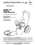
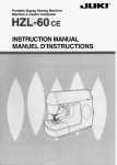
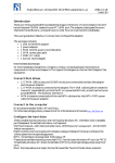
1.
Connect Hose e n d G u n (Refer to Fig 1.)
a.Remove
the plasticcapplugfromthefilter
50 f t (15.2 m) main
outlet nipple and screw the
fluid hose onto the nipple.
b. Connect the whip hose between the fluid hose
and the gun inlet connection.
c. Don't use thread
spray tip yet1
sealant, and don't install
the
WARNING
If you are supplying your own hoses and spray
gun, be sure they are electrically grounded and
ratedfor
a t least 25do psi (175 bar1 Working
Pressure, and that the gunhas a tip guard. This is
to reduce the risk of serious bodily injury caused
bystaticsparkingandfluidinjection
or overpressurizing and rupturing the equipment.
Fig 1
To
avoid damaging the pressure control, which
may result in poor equipment performance and
component damage, follow these precautions:
I
C
A
U
T
'
O
N
1
1. Always useflexible,groundedsprayhose
of at least 50 ft 115.2 m) long.
2. Never use a wire braid hoseas it is too rigid
to act as a pulsation dampener.
3. Neverinstallany
shutoffdevicebetween
the filter and the main hose. See Fig 2.
4. Always use the main filter outlet for onegun operation. Never plug this outlet.
2.
i......
,..,..,~. ..
... .
Fill Packing NutlWet-Cup (SeeFig 2.)
Fill the packing nut/wet-cup 113 full with Graco
Throat Seal Liquid ITSL), supplied.
3. CheckElectricalService
a.
Be sure
the
electrical
service is
60 HzAC, 15 Amp(minimum)and
120 V,
that the
outlet you use is properly grounded.
b.
, .. .. ..
.. .
Use an extension cord which has 3 wires of a
minimum 12 gauge size, andamaximumof
150 ft 1 4 5 m) long. Longer lengths may affect
sprayer performance.
4. Plug in the Sprayer
a. Be suretheON/OFFswitch
Fig 3.
is OFF. Refer to
b.Plugthepowersupplycordintoagrounded
electilcal outlet that is at least
20 ft 16 m) away
from the spray area t o reduce the chance of a
spark igniting the spray vapors.
c.
. .
Do not removethethirdprongofthepower
supplycordplug,whichisthegrounding
prong, and do not use an adapter.
5. Flushthe
pump to remove thelightweightoil
which was left in t o protect pump parts after factory testing.
a. Before using water-base paint, flush with
mineralspirits followed by soapy water,and
then a clean water flush.
Fig 3
6.
Prepare the paint
according to themanufacturer's
recommendations.
a. Remove any skin that may have formed.
b.
Stir the paint to dissolve pigments.
c. Strain the paint through a fine nylon mesh bag
(available at
most
important
step
toward
trouble-free spray paintdealers) t o remove partip. This
t i c k that could clog the filter or spray
is probably themostimportant step toward
trouble-free spray painting.
b. Before usingoil-base paint, flush with mineral
spirits only.
c.
See FLUSHING GUIDELINES on page 12 for
flushing procedure.
307-830
9
WARNING
Pressure Relief Procedure
To reduce the risk of seriousbodilyinjury,
including fluid injection or splashing in the eyes or
on theskin, or injury from moving parts or electric
shock,always
followthisprocedurewhenever
you shutoff the sprayer, when checking or servicing any part of the spraysystem, when installing,
cleaningorchangingspray
tips, andwhenever
you stop spraying.
Engage the gun safety latch.
Turn the ON/OFF switch to OFF.
Unplug the power supply cord.
Disengage the gun safety latch.
Hold a metal part of the gun firmly to the
side of a metal pail, and trigger the gun t o
relieve pressure.
6. Engage the gun safety latch.
7. Open the pressure relief valve, having a
container ready to catch the drainage.
8. Leave the pressurerelief valve openuntil
you are ready to operate the sprayer again.
MAINTAIN FIRM
METAL-TO-METAL
CONTACT BETWEEN
GUNANDGROUNDED
METAL CONTAINER
1.
2.
3.
4.
5.
Ifyou suspect that the spray tip or hose is completely clogged, or thatpressure hasn o t been fully
relieved after following the steps
above, VERY
SLOWLY loosenthetipguardretainingnut
or
hose end coupling and relieve pressure gradually.
Then loosen thenut completely. Now clear the tip
or hose obstruction.
1.
2.
b.
c.
spray tip yet1
Put the suction tube into the paint container.
d. Turn the
pressureadjustingknoball
the way
counterclockwise t o lower thepressure setting.
e.
Disengage the gun safety latch.
f. Hold a metal part of the gun firmly against and
4.
aimed into a metal waste container. See Fig 4.
Squeeze the trigger and hold it open, turn the
ON/OFF switch t o ON, and slowly increase the
pressure setting until the sprayer starts. This
procedurereducesthe
risk ofstaticelectric
dischargeand splashing. Keep theguntriggered until all
air is forced out of the system and
the paint flows freelyfrom the gun.
Release the
trigger and engage the safety.
NOTE:
If thepumpishardtoprime,place
a containerunder the pressurereliefvalve
and
open it. When fluid comes from the valve,
close it. Then disengage the gun safety latch
and proceed as in Step If, above.
g. Check all fluid connections for leaks. If any are
found, follow the Pressure Relief Procedure
Warning, above, then tighten connections.
10
307-830
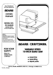
Refer t o manual 307-848, supplied withthe
gun, for how to install the tip guard and tip.
3. Adjusting the Spray Pattern
Prime the Sprayer with Paint.
a. Close the filter's pressure relief valve. See Fig 1.
b. Don't install the
Install the Tip Guard end SwitchTip (Refer t o
Fig 5.)
a. Be sure the gun safety latch is engaged.
a.
Increase the fluid pressure control knob setting
justuntilsprayfromtheguniscompletely
atomized.Toavoidexcessiveoversprayand
fogging, and t o decrease tip wear and extend
the life of the sprayer, always use the lowest
possiblepressureneeded
to getthedesired
results.
b. Ifmorecoverage
is needed, use a larger tip
rather than increasing the pressure.
c. Test the spray pattern. To adjust the direction
of the spraypattern,engage the gun safety
latch and loosen the tip guard retaining nut.
Position thetip so the groove is horizontal for a
horizontal pattern or vertical for a vertical pattern. Then tighten the retaining nut.
Refer t o
Fig 5.
Operating Tips. These suggestions will help prevent the motor from running too hot or operating
intermittently.
a. Decrease the pressure when using a small tip.
b. Keep the sprayer in a shaded area when spraying outdoors.
c.
Turn off the sprayer and
relieve
pressure
whenever you stop spraying.
.5.
Cleaning e Clogged Tip
CAUTION
Never leave water or any paint
in the sprayer overnight to: (1) prevent pump corrosion; (2) to prevent the paint or waterfrom freezing in the pump
andpressure controlwhichcan
cause loss of
pressure, stallingor
serious sprayerdamage.
Always use mineralspirits
forthefinalflush.
Relieve pressure. This leaves a protective coating
of mineral spirits in the sprayer.
WARNING
To reduce the risk of
serious bodily injury from
fluid injection or splashing in the eyes or on the
skin, use
extreme
caution
when
cleaning
or
changing spray tips. If the spray tip clogs while
spraying, engage the gun safety latch immediately, thenfollowtheprocedureinSteps
5a-S.
below.
NEVER wipe off build up around the spray tip until
pressure is fully relieved and the gun safetyis latch
engaged.
...
a.
.
b.
Clean the front of the tip frequently during the
day'soperation.
First, followthePressure
Relief Procedure Warning onpage 10. Then
use a solvent-soaked brush t o keep paint from
building up and clogging thetip.
4.
For very short shutoff periods, leave the suction
tube in the paint, follow the Pressure Relief Procedure Warning on page 10, and clean the spray
tip.
5. Coil the hose and hang it on the hose rack when
storing it, even for overnight, t o help protect the
hose from kinking, abrasion, coupling damage, etc.
h
If the spray tip does clog, release the gun trigger, engage thegun safety, androtatethe
spray tip handle 180°, so the arrow points back
to the gun. See Fig 5.
c. Disengage the gun safety latch and trigger the
gunintoawastecontainer.Fluid
pressure
should forceout the clog.Engage the gun safety latch again.
. . . ..
d. Return the handle tothe
originalposition,
disengage thegunsafetylatch,andresume
spraying.
e. If the tip is still clogged, engage the gun safety
latch,shut off andunplugthe
sprayer, and
open
the
pressure
relief valve t o relieve
pressure. Clean thespray
tip. See manual
307-848.
..
. ...
....... ..:,..
.,
.
.
... .~.
. ,
SHUTDOWN AND CARE
1. Checkthepackingnutlwet-cupdaily.
First
follow the Pressure Relief Procedure Warning
on page 10. Be sure the wet-cup is 1 /3 full of TSL
at all times to help prevent paint buildup on the
piston rod and premature wear of packings. The
enough
to
stop
packing nut should be tight
leakage, but no tighter. Overtightening may cause
binding and excessive packing wear. Use a screwdriverandlighthammer
t o adjust the nut. See
Fig 6.
Fig
5
.
.: . .
2. Cleanthe
fluid filter often andwhenever the
sprayer is stored. First follow the Pressure Relief
Procedure Warning onpage 10. Refer to manual
307-273, supplied, for the cleaning procedure.
PACKING NUTI
3. Flush the sprayer at the endof each work day
and fill it with mineral spirits to help prevent pump
corrosion and freezing. See "Flushing Guidelines"
on page 12.
307-830
11
FLUSHING GUIDELINES
When to Flush
1. NewSprayer.
Your new sprayer was factory
tested in lightweight oil which
was left in to protect
pump parts.
Before using water-basepaint, flush with mineral
spirits, followed by soapy water, and then a clean
water flush.
Beforeusingoif-base
paint,flushwith
mineral
spirits only.
2.
Changing Colors. Flush with a compatible solvent
such as mineral spirits or water.
5. Storage.
Water-base p a i n t flush with water, then mineral
spirits and leave the pump, hose and gun filled with
mineral spirits. Shut off and unplug the sprayer,
open the pressure relief valve to relieve pressure
and leave open.
Oil-base paint: flush with mineral spirits. Shut off
andunplugthe sprayer, open the pressure relief
valve to relieve pressure and leave open.
6. StartuDafter s t o r a m
Before.using water-&ase paint, flush out mineral
3. Changingfromwater-base
to oil-basepaint.
spirits
with soapywaterand
then a clean water
Flush with soapy water, then mineral spirits.
flush.
4. Changingfromoil-basetowater-basepaint.
When usingoif-base paint,
flush
out
the
mineral
Flush with mineral spirits, followedby soapy water,spiritswiththepaintto
be sprayedand the sprayer
then a clean water flush.
is ready to use.
H o w t o Flush
1. Follow the Pressure Relief Procedure Warning
on page 2 or 10.
2. Remove thefilterbowland
screen; see manual
307-273 supplied. Clean the screen separately and
install the bowl without the screen to flush it. See
Fig 7.
MAINTAIN FIRM
METAL TO METAL
CONTACT BETWEEN
GUNANDGROUNDED
METAL CONTAINER
Fig 8
theON/OFFswitchto
ON and slowlyturnthe
pressure adjusting knob clockwise just until the
sprayer starts. Keep the gun triggered until clean
solvent comes from the nozzle. Release the trigger
and engage the gun safety latch.
Fig 7
3. Close the filter pressure relief valve.
4. Pour one-half gallon (2 liters) of compatible solvent
into a bare metal pail. Put the suction tube in the
pail.
5. Remove the spray tip from the gun.
WARNING
splashing, always remove the spray tip from the
gun, and hold a metal part of the gun firmly to the
side of and aimedinto a grounded metal pail when
6. Disengage the gun safety latch. Point thespray gun
into a grounded metal waste container and with a
7. Check all fluidconnectionsfor leaks. Ifany leak,
first follow the Pressure Relief Procedure Warning on page 2 or 10. Now tighten the connections,
start the sprayer, and recheck the connections for
leaks.
8. Remove the suction tube from the pail. Disengage
the gun safety and trigger the gun to force solvent
from the hose. Do not let the pump run dry for
more than 30 seconds to avoid damaging the
pump packingslThen turn ON/OFF switch toOFF
and engage the gun safety latch.
9. Unplug the power supply cord.
Open the pressure
relief valve andleave open until youare ready t o use
the sprayer again. Unscrewthefilterbowl
and
reinstall the clean screen. Reinstall the bowl, hand
tight only.
metal part of the gun firmly touching the metal con10. If you have flushed with mineral spirits and are gotainer, squeeze theguntrigger.
See Fig 8. This
ing to use a water-basepaint,flush
with soapy
procedure haips reduce the risk of static sparkwater followed bya clean water flush. Then repeat
ing and splashing. With the gun triggered, turn
Step 1.
12
307-830
-
.~
~.
~
APPLICATION METHODS
Always hold the gun perpendicular t o the surface and
keep the gun at an even
12 to 14 in. (300-356rnml from
the surface you are spraying. See Fig 9.
Beginmovingthegunin
a horizontaldirectionat
a
off the target surface
steady rate. Start the spray stroke
and pull the trigger as thegun is moving. Then, while
the gun is still moving, and as you approach the other
edge,release the trigger. This method avoids
excess
paint buildup at the end of each stroke.
..
Do not try to increase coverage by increasing the fluid
pressure1 Using the lowest pressure necessary t o get
thedesiredresultswillhelpprolong
the life of your
sprayer and minimize paint lost by overspray.
For interior corners, such as on a bookcase or inside a
cabinet, aim the gun toward the center of the corner
to
spray. By dividing thespray pattern thisway, the edges
on both sides are sprayed evenly. See Fig 11.
...
...
The best way to control
the rate of coverageis with the
gun ti. size. A smal tip orifice applies less paint and a
narrower pattern. A larger tip orifice applies more paint
and a wider pattern.
...
~..'
. . . ...
RIGHT
.... .......
... ....,
Fig 11
If there is a wind, angle the spray patterninto the wind
t o minimize drifting. Paint from the groundt o the roof.
I
WRONG
I
Fig 9
The correct speed for moving the gun will allow a full,
wet coating to be applied without runs
or sags. Lapping
each stroke about 50% over the previous stroke proin a
ducesuniformpaintthickness.Andspraying
uniform pattern alternatelyfrom right
t o left, then leftto
right, provides a professional finish. See Fig 10.
Shrubs. When next to thehouse, tie back shrubs from
the surface t o be painted with rope and stakes. Then
cover them with a canvas dropcloth as the paint approaches the area. Remove the canvas dropcloth as
soon as the area is painted, to prevent possible damage
to the shrubs.
Concrete walks. If the walkwayswillbewalked
on,
cover them with a canvas dropcloth to avoid slipping.
Otherwise a plastic dropcloth is all that is needed.
Electric1outlets and lamps. Protectelectricaloutlets
with masking tape. Cover lamps with plasticbags
secured with masking tap.
Nearby objects. Move objects suchas automobiles, picnic tables, lawn furniture, etc. upwindof the surface to
be sprayed. In the case of a nearby home, make a protectivebarrier by hangingplasticbetween
two long
poles.
Fig 10
\
307-830 13
~~~~
SERVICE
WARNING
To reduce the risk of
serious bodily injury, including
fluid injection; splashingin the eyes or on the skin; injury from
moving parts or electric
shock, always follow this procedurewhenever you shutoff the sprayer, when checkingor
servicing any part of the spray system, when installing, cleaning or changing spray tips, and whenever you stop
spraying.
1.
2.
3.
4.
Engage the gun safety latch.
Turn the ONlOFF switch OFF.
Unplug the power supply cord.
Disengage the gun safety latch.
5. Hold a metal part of the gun firmly tothe side of a grounded metal pail, and trigger the gunt o relieve pressure.
6. Engage the gun safety latch.
7. Open the pressure relief valve, having a container ready to catch the drainage.
8. Leave the pressure relief valve open until you are ready to spray again.
. .
I
If you suspect teh spray tip or hoseis completely clogged, or that pressure hasnot been fully relievedafter following the stepsabove, VERY SLOWLY loosen the tip guard retaining nut or hose end coupling and relieve pressure
gradually, then loosen completely. Now clear the tip or hose.
.. . ..
~~~
~
CAUSE
SOLUTION
Power or extension cord unplugged, or damaged
or building circuit fuse blown
Motor overload switch* has opened
Check, reset or replace
Pressure setting too low
Pressure control frozen or damaged by over
pressurization
Power or extension cord unplugged, or building
circuit fuse blown
Motor overload switch* has opened
. , ,.
. ... ..,. .,
Pressure setting too low
Spray tip or filter plugged
Wrong type extension cord
Electric motor runs, but low of
no paint output and pump not
..,.. :,..
.
.
stroking lSee PROBLEM "Noi
enough paint pressure". on
page 15, also.)
Piston ball check not seating
Piston packings worn or damaged
Intake valve ball checknot seating
Pump frozen
Filter upside down
Pressure control frozen or damaged by over
pressurization
Gear train damaged
Worn pump parts
Sprayer not primed
Throat packings worn or damaged
Unplug power cord, relieve pressure,
allow to cool, decrease pressure
Increase
Thaw", change, remove or clean"',
replace, see page 20
Check,resetorreplace
Unplug power cord, relieve pressure,
allow to cool, decrease pressure
Increase
Remove and clean
Use maximum 150 ft (45 m), 3 wires 12
gauge minimum, grounded extension
cord
Service, see 307-733
Replace, see 307-793
Service, see 307-793
Thaw"
Remove and reinstall
Thaw.', change, remove or
clean***,
replace, see page 20
Replace
Service, see 307-793
Prime sprayer, see page 10
Replace, see 307-793
Troubleshooting Chart Continued onpage 15.
~ _ _ _ ~
~~
~
TROUBLESHOOTING CHART Continued
PROBLEM
CAUSE
SOLUTION
Spray tip or filter plugged
Spray tip too big or worn
Paint too viscous
Wrong type hose
Remove and clean
Change spray tip
Thin
Use minimum 50 ft (15.2 m) grounded,
flexible hose lwire braid hnaa
unacceptable)
Increase
Change spraytip
Thaw'.,
change, remove or clean'*+,
replace, see page 20
Service. see manual 307-793
Increase
Clean-see manual 307-273
Change spray tip
Fill
Thin
Use minimum 50 ft (15.2 m) grounded,
flexible hose (wire braid hose unaccep-
I
I
Tails or fingers in spray pattern
.
Pressure setting too low
Spray tip too big or worn
Pressure control frozen or damaged by over
pressurization
Worn pump parts
Pressure setting too low
Outlet filter dirty or plugged
Spray tip too big or worn
Paint supplyiow or pail empty
Paint too viscous
Wrong type hose
.
tahlel
Static sparking from spray gun
Spray tip too big or worn
Paint supply low or pail empty
Sprayer sucking air or gun needle not seating
Change spraytip
Fill
Tighten fittings, service gun-see
manual 307-633
Sprayer or work not grounded
Check, ground
'The electric motor has an ove~ mating protector switch which automatically resets on cooling. If it opens and the electric
motor shuts itself off, unplug
e power cord and letthe sprayer cool for 30 to M) minutes.
. .
'*Freezing results from failure to replace water-base paint or flushing waterwith mineral spirits solvent.
***Over pressurization results from (11 using less than 50 f i 115.2 ml of nylon spray hose, (21 using a wire braid spray hose, (3)
adding a shutoff device between the pump outlet and the spray gun, (4) attaching a spray hose to the pressure relief valve, or
(5) using a clogged or incorrectly assembled filter.
..,.... . .
.
I
~~
.
!
307-830
-15
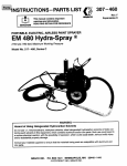
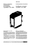
BEARING HOUSING
CONNECTING ROD REPLACEMENT (See Fig 12 and 13)
IW
Before doing this procedure, follow the Pressure
Relief Procedure Warningon page 14 to reduce
the risk of an injection injury, injury from moving
parts or electric shock. Unplug the sprayer1
1. Stop the sprayer a t the bottom of its stroke to get
the crank (E) in its lowest position. If the crank ( E )
must be loweredmanually,carefullyrotatethe
blades of the fan with a screwdriver.
2. Remove the front cover and screws (12, 13).
3. Unscrewthesuction'tube
(3) fromthepump,
holding a wrench on the pump intake valve to keep
the pump from loosening.
4. Disconnectthepumpoutlet
hose (30)fromthe
displacement pump outlet nipple (32).
5. Use a screwdriver to push aside the retaining spring
( 4 9 1 a t the top of the pump. Push the pin ( 5 0 ) out
the rear.
6. Loosen the jam nut (61 with an adjustable wrench.
Unscrew and remove the displacement pump.
..
7.Use a 3/16" hex key wrench to remove the four
screws (9) and lockwashers (10) from the bearing
housing.
'
8. Lightly tap the lower rear of the bearing housing
(51) with a plastic mallet to loosen it from the drive
housing.Thenpullthebearinghousingandthe
connecting rod assembly ( 5 2 ) straight off the drive
housing.
9. Inspect the crank(E) for excessive wear and replace
parts as needed.
..:.. .. .
.. . . . ...
10. Evenly lubricate the inside of the bronze bearing in
the bearing housing with high quality motor
oil.
Liberally pack the roller bearing in the connecting
rod assembly (52) with bearing grease.
11. Assemble theconnectingrod
( 5 2 1 andbearing
housing (51I.
12. Clean the mating surfaces of the bearing and drive
housings.
crank ( E ) and
carefully align the locating
pins in the drive housing
with the holes in the front cover (12). Push the
bearing housing onto
the drive housingor tap it into
place with a plastic mallet.
13. Align the connecting rod with the
Fig 13
IC
00 NOT use the bearing housingscrews (9) to try
. .. . .
WARNING
to align or seat the bearing housing; the bearing
and drive housing will not align properly and will
result in premature bearingwear.
Be sure the retaining spring ( 4 9 1 is firmly in the
groove of the connectingrod, all the way around,
to prevent the pin 1 5 0 ) from working loose due to
vibration. See Fig 13.
14. Install the screws (9) and lockwashers (10) on the
If the pin works
loose, it or other partscould break
off due to the force of the pumping action.
These
parts couldbe projected through theair and result
in serious bodily injury or property damage, including damage to the pump, connecting rod or
bearing housing.
bearing housing and tightenevenly.
314 of the
15. Screwthedisplacementpumpabout
way into the bearing housing
151). Hold the pin (50)
up to the pin hole in the connecting rod assembly
(511 and continue screwing in the pump until the
pin slides easily into the hole. Back off the pump
until the top threads of the pump cylinder
are flush
with the face of the bearing housing and the outlet
nipple (32)is facing back. Push the retaining spring
149) into the grooveall the way around the connecting rod. Tighten the locknut 16) very tight-about
75-85 ft-lb (102-115 N m ) - w i t h a 2 in. open end
wrench and a light hammer. See Fig 13.
16
307830
16. Reinstall the front coverand screws (9, 10). Recon(31 and pump outlet hose
nect the suction tube
(30).
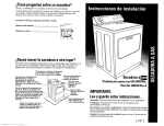
DRIVE HOUSING REPLACEMENT (See Fig 141
WARNING
Relief Procedure Warning on
page 14 t o reduce
the risk of a fluid injection injury, injury from mov-
NOTE:
Stop the sprayer at the bottom of its stroke
to get the crank (E) in its lowest position.To
lower it manually, carefully rotate the blades
of the fan with a screwdriver.
1. Remove the front cover and screws (12, 13).
hose (30)fromthe
2. Disconnectthepumpoutlet
displacement pump outlet nipple (32).
3. Use a 3/16 in. hex key wrench to remove the four
screws (9)and lockwashers (10) from the bearing
housing.
Lightly tap the lower rear of the bearing housing
(51) with a plastic mallet to loosen it from the drive
housing. Then pull the bearing housing and connecting rodassembly straightoff the drive housing.
5. Use a 114 in. hex key wrenchto remove the screws
( 5 3 ) andlockwashers ( 5 4 ) fromthe rear ofthe
motor front end bell (F).
4.
6,
Lightly tap the drive housing with
a plastic malletto
bell, then pullit straight
loosen it from the front end
CAUTION
1
DO NOT allow the gear cluster ( 5 6 ) t o fall when
removingthedrivehousing
(14). It is easi/y
damaged if dropped. The gear may stay engaged
in either
the
front
bell or
end
drive
the
housing.
DO NOT lose the thrust balls (14c and16b)
located at each end of the gear cluster ( 5 6 1 or
allow them t o fall between gears. The ball, which
is heavily coveredwith grease, usually staysin the
shaft recesses, but could be dislodged. If caught
betweengearsand
not removed, theballswill
seriously damage the drive housing.
If the balls
are
not in dace. the bearinas will wear orematurelv.
7. Liberally apply bearing grease to the gear cluster
(56). Check to be surethe thrust balls (14c and 16b)
are in place.
8. Place the bronze-colored washer(14b) and then the
silver-colored washer (14a) on the shaft protruding
from the big gear in the drive housing (14). Align
the gears and push the new drive housing straight
onto the front end bell and locating pins.
5 and working backwards, continue t o reassemble the sprayer.
9. Starting at Step
Off.
Fig 14
307-830
17
i
i
MOTOR REPLACEMENT (Refer to Fig 15 and 16)
rWA
Before doing this procedure, follow the Pressure
Relief Procedure Warning on
page 14t o reduce
the risk of a fluid injection injury, injury from moving parts, or electric shock. Unplug the sprayer1
11. Use a plastic mallet to gently tap the displacement
pump (4) from therear t o loosen the drive housil
from the front endbell. Then pull the drive housit
away from the end bell.
CAUTION
~~~~
( 3 0 1 fromthe
1. Disconnect the pumpoutlethose
displacement pump outlet nipple (32).
2. Remove the screws (20)
and pressure control cover
(21) and disconnectthe four motorleads: a red one
from the Dressure switch (F). a red one from the
over-prekure switch (G), a n d t w o black ones from
the bridge (117). See Fig 15.
t o loosentheconduit
3. Use anadjustablewrench
connector nut (103) at the pressure control
assembly (23).
4. Swingtheconduit(27)awayfromtheconduit
elbow (103).
5. Remove the conduitseal (181 from around the wires
inthe
pressure
control.
Pull
themotor
leads
through the elbow, one at a time.
CAUTION
Always pull the motorleads one at a time to avoid
loosening the terminals which could result ainbad
connection and poor sprayer performance.
6. Loosen the nut of the connector (25) at the motor
and pull the conduit(27) away from the motor, then
pull the leads through the conduit, one at a time.
7. Unscrew the connector elbow from the motor.
8. Pull the wires through the elbow, one at a time.
9. Remove the front cover and screws (12, 13).
10. Use a 1/4" hex key wrench t o remove the screws
(53) and washers ( 5 4 ) from the rear of the motor
front end bell (FI.
DO NOT allow the gear cluster ( 5 6 ) to fall when
removing the drivehousing(14).
It is essi/y
damaged if dropped. The cluster may stay engaged in either the frontend bell or the drive housing.
DO NOTlosethethrustballs
(14c and16b)
( 5 6 ) or
located a t eachendofthegearcluster
allow them to fall between gears. The ball, which
is heavily coveredwith grease, usually staysin the
gear recesses, but could be dislodged. If caught
betweengearsand
not removed, theballswill
seriously damage the drive housing. If the balls
are
not in place, the bearings will wear prematurely.
12. While supporting the motor to
keep the sprayer
(33). lockwashers
from tipping,removethenuts
(341, and capscrews (35) holding the motormounting plate to the frame. Lift the motor assembly off
the frame.
13. Place the new motor assembly on the frame.
14. Liberally grease the gear cluster ( 5 6 ) andpinion
end
gear (PI andpack all bearings in the motor front
bell. Check to be sure the thrust balls (14c andl6b)
are in place.
15. Place the bronze-colored washer (14b) and then the
silver-colored washer (14a) on the shaft protruding
from the big gear in the drive housing (14).
16. Align the gears andpush the drive housing (14)
straight onto the front endbell and locating pins.
17. Starting at Step 10 and working backwards, continue to reassemble the sprayer.
NOTE:
Use a turningmotionontheconduitwhen
feeding wires through it.
18. Reinstall the conduit seal (18) around the wires
in the
conduit elbow (103) at the pressure control to keep
contaminants from entering thepressure control.
19. Reinstall the pressure control cover.
18
307430
Fig 15
Fig 16
307-830
19
REMOVING and REPLACING PRESSURE CONTROL
WARNING
cluding fluid injection; splashing in the
eyes; injury
from moving parts or electric
shock, always follow
the Pressure ReliefProcedureWarningon
page 14 before continuing.
Hold the nut (HI at thepressure control with a wrench
to prevent it from moving,andunscrew
the swivel
union(31)fromthenipple
(105e). Remove thefilter
(15).
Holding the elbow(105d) steadywith a wrench, disconnect the hose (30)from the nipple (105f).
Unscrew the conduit nut (103a) from the conduit (27).
Pull the pressure control ( 2 3 ) away from the conduit
while carefully guiding the wires through the connector
(25).
Loosen the knurledpart ofthestrain
relief bushing
(101). and unscrew it from the pressure control. Slide
the bushing up on the power cord (102). Unscrew the
conduit connector (25) from the box.
Remove the power supply cord and strain relief bushing
fromtheoldboxand
assemble t o thenewbox.
Reassemble allotherparts
inthe reverse orderof
disassembly.
CAUTION
(105d)or nipple (10%) from the pressure control.
Any twisting or jarring of the pressure control fitting could alter the factory setting of the control or
(34)and nuts (33).
Remove the screw (35). lockwashers
Remove the pressure control (23) from the frame.
Remove thescrews
pressure control.
(20) andcover(21)
fromthe
Disconnect the threepowercord
leads from:the
grounded screw (10'3, the overpressure switch(GIand
thecircuit breaker(115).Disconnect
thefourmotor
leads: two black leads from the bridge (117). one red
lead from thepressure switch (F) and one red lead from
the overpressure switch (G).See Fig 18.
. .,.., .,.,..~...,.
.,..
.. .. .,.
..
,..., '
:... .
,.
. .
Fig 17
20
307-830
I
I
Failure t o ObSeNe the following may cause poor
performance or excessive pressure and permanent
damage to the pressure control:
C
A
U
T
l
O
N
(1)Always use grounded,flexiblesprayhoseat
50 ft (15.2 m)minimum length.
(2)Never use a wire braid sprayhose.
(3)Never add any type of shutoff device between
the pump outlet and the spray gun.
14)Be sure t o check filter for cloggingor incorrect
assembly if tip clogging frequencyincreases.
(5)Never allow flushing water or waterbase paint
to freeze in the system.
l
I
'i
!
7 * / , 103
9 $&
Fig 18
.'
'
~
. .
..,.... .,.
.
.
.' . '
''
"I
I
i
307-830
21
PRESSURE CONTROL CALIBRATION (See Fig 19)
W ARNlAlG
I
USE EXTREME CAUTION WHEN PERFORMING THIS CALIBRATION PROCEDURE
reduce
to the risk of a
fluid injection injury or other
serious bodily injury which can result from component rupture, electric
shock, fire, explosion, or moving parts.
This procedure sets the sprayer t o 2500 psi (172 bar)
MAXIMUM
WORKING
PRESSURE.
Thisproceduremustbeperformedwhenevera
microswitch,or pressure control assembly is removed and reinstalled or replaced to be sure the sprayer
is properly calibrated.
Impropercalibrationcan cause the sprayer to over-rated
pressurize and result in component rupture, fire or
explosion. It may also preventthesprayer from obtainingthemaximumworking
pressure whichwould
result in poor sprayer performance.
NEVER attempt to increase the fluid outlet pressure
performing
by
these
calibrations
other
any
way.
in
2500 psi (172 bar)MAXIMUM
NEVER
EXCEED
WORKING PRESSURE. Normaloperationofthe
sprayer athigher pressures couldresultincomponent rupture, fire or explosion.
ALWAYS use a new 50 foot (15.2 m) spray hose
for 3000 psi (210 bar)MAXIMUMWORKING
PRESSURE whenperformingthisprocedure.A
used, underratedhosecoulddevelopahighpressure
leak or rupture.
in the pressure control
AVOIDtouchingthewire
assembly when the control box cover is removed to
reduce the risk of electric shock.
Tools Needed:
NEW 50 ft (15.2 m) 3000 psi (210 bar) airless spray
hose, Part No. 210-541
Needle valve, Part No. 102-715 or 103-067
318" open.end wrench
Fluid-filled pressure gauge, Part No. 102-814
5 gallon pail and water
Mineral spirits (for flushing after test)
1.
2.
Follow the Pressure Relief Procedure Warning
on page 14. Install the new 50 ft (15.2 m) spray
hose t o the sprayer outlet. On the other end of the
hose install the needle valve. Install the fluid-filled
pressure gauge in the top port of the fluid filter.
Open the needlevalveslightly. Turn the pressure
control knob ( D l t o the minimum setting. Plug in
the sprayer and turn the switch ON. Increase the
pressure setting just enough t o start the sprayer.
Prime the hose, being sure to eliminate all air from
the system.
3. Open the needle valve alittlemore-enough
to
allow the pump to run continuously-and turn the
pressure controlknobtomaximum.Now,very
slowly start t o close the needle valve, but don't
close it all the way. Observe the Dressure a t which
the pump stalls, 'whichshould be approximately
2500 psi (172 bar).
NOTE:
4.
Now check to see atwhat pressure the sprayer
starts to runagain after stalling. Plug in the
sprayer,
turn it on, closetheneedle
valve, and set the
pressure a t maximum. Allow thesprayer to run until
it stalls.
5. Now open the needle valve very slowly while observing the pressuregauge. Check to see if the
pressure drops to approximately 2100 psi (147 bar1
before starting again.
Ifthe pressure is lower: shut off and unplug the
sprayer, but do not relieve pressure. Turn the differential wheel (F) counterclockwise just one notch
and repeat Steps 4 and5. Check the pressure drop
again, and repeat if necessary.
NOTE:
6. FollowthePressureReliefProcedureWarning
on page 14, flush the waterout with mineral spirits,
relieve pressure again, then remove the test hose,
needle valve and pressure gauge.
Theslowerthepressureisbrought
up, the
easier it is to note the exact stall pressure.
Closing the needle valve quickly causes the
pressure t o rise too fast which gives a false
reading.
If the pressure is lower: unplug the sprayer and
relieve pressure. Use a 318' open end wrench t o
turn the pressure adjustment nut, at the bottom of
the pressure control knob shaft (R), counterclockwise 118 turn or less, then repeat steps 2'and 3.
If the pressure is higher: unplug the sprayer and
relieve pressure. Turn the pressure adjustment nut
clockwise 1 I8 turn orless and repeat steps2 and 3.
Repeat until the proper stall pressure is obtained.
Fig 19
22
307830
Ifyouadjustthedifferentialwheel,recheck
the stall pressure (steps 2 and 3) to be sure
the stall pressure has not changed.
PARTS DRAWING
Ref No. 23
Pressure Control Assembly
Part No. 220-903
includes items 101 to 121
105f
PARTS LIST
REF PART
NO. NO.
DESCRIPTION
108-295
101
102 220.945
103
108460
104V78-035
105 220-905
BUSHING, strain relief
CORD, power supply, 8112'
CONNECTOR, conduit, 450
LABEL, warning
BOX, pressure control, bare
Includes replaceable items 10% to
105f
l f f i 105679 .ON/OFF SWITCH
105b 107-255 .GUARD, locking
10%
105-659 .BOOT, onlaff switch
105d 100-840 .ELBOW, street; 114 nptfmx f )
1157-350 .ADAPTER, 318 nptlml x 112 nptfml
105f 162-453 .NIPPLE, 114 nptfmlx 114 npsm
106
100-035
SCREW, mach. slot pan head;
No. 8x5116
107
157-021
110 100-072
LOCKWASHER, No. 8 internal
NUT, hex, mscr; No. 8-32UNC-2B
QTY
REF PART
NO.
NO.
1
1
111
107-023
103-181
112
113 107-070
1
1
1
1
1
1
1
DESCRIPTION
QTY
VARISTOR
LOCKWASHER,
NO.
8
SCREW.
mach. flat head:. No.
6-32x 518"
107-254 BOOT, circuit breaker
107-256 CIRCUIT BREAKER
'178-797 LABEL, warning
10B-219 BRlDGElRECTlFlER
218-916 TRlAC
108-763 SCREW. mach. filhd:. No. 8-32
UNC.
.~
2a x 0.812"
NUT,
hex,
mscr;
No.
6-32UNC-2a
100-284
WIREJUMPER
1
2
~~
114
115
116
117
118
119
1
120
1
218-168
121
~
~
1
2
See "How To Order Replacement Parts"on page 25.
2
*Additional warning labels are available
at no charge.
1
1
2
307-824 23
. .
PARTS DRAWING
Modal 220-856, Series A
Includes items 1 to 62
. .
.
,.. ,.:
. ..
.., ..,.. . .. ..,
.,?:j>'
..
s:.
.
... .,.. ..... ,
:.
. . . .. .
'"7
14b7
PARTS LIST
Model 220-866, Series A
E M 590 Basic Sprayer
Includes items 1 t o 64
Model 231-590
EM 590 Basic Sprayer
Includes items 1 to 79
REF PART
DESCRIPTION
QN
NO. NO.
1
lb
IC
2
3
4
Includes replaceable items la-lc
101-242 .RING, retaining
176-884 .WASHER. plain, 5/8"
107-310 .PLUG, plastic
181-072 STRAINFR
- . ... ....-. .
180-573 TUBE, intake
217-577 DISPLACEMENT PUMP
See 307-793for parts
108-662 NUT. retainer
178-941 NUT. hex
183-037 HANGER, pail
183-035
107-210
..
. .
. .
, .
. . .. ..
.:
10
11
12
13
14
106-115
183-329
183-333
107-156
220-859
14a
14b
14C
15
179-936
107-089
100-069
214-570
16
220-855
16a
17ao94
1w-069
107-263
102-799
107-447
106-075
16b
16c
1€d
18
20
21
22
23
24
25
n
183-383
183-371
220-858
*1nm
108-460
065-099
ordering
., ...
.,~...
NO. NO.
220-365 CART ASSEMBLY
la
REF PART
30
218-083
31
155-665
1
2
32
33
34
35
39
1
40
1
2
41
162-453
100-188
100-214
101-344
150-513
100-322
179-345
42
43
100.509
178-034
44
45
48
49
50
51
52
53
220-286
106-062
104-811
176-817
176818
21ao35
218-034
100-643
54
56
62
75
105-510
179-961
206-994
210-541
76
214-701
n
220-956
1
1
1
2
1
1
BRACKET
CAPSCREW, sch; 1/4-20
unrc-3a x1 .O"
4
4
LOCKWASHER, spring, 3/8"
BRACKET, mounting
1
1
COVER, drive housing
6
SCREW, mach. pnh; 632x 5/8"
DRIVE HOUSING
Includes replaceable items 14.14~
1
.WASHER, silver-colored
1
1
.WASHER, bronze-colored
1
.BALL, 1/4" sst
FILTER, fluid
See 307-273for parts
1
MOTOR, electric, 3/4HP
Includes replaceable items 16a-16ci
1
.LABEL. warning
1
i
.BALL, 1/4", s
1
.TERMINAL (see Page 2 3 )
2
.TERMINAL (see Page 2 3 1
2
SEAL, condult (see page 2 3 1
1
SCREW, mach. oval head;
10-24x 1/ 2 "
8
COVER, pressure control
1
LABEL, identification
1
PRESSURECONTROL
See page 23 for parts
1
LABEL: warning^
1
CONNECTOR, conduit, 4 5 O
1
CONDUIT, electrical; specify lengrh
when
0.79'
DESCRIPTION
QTY
HOSE, nylon: 114" ID cpld
114 npsmlfbe) 29" (740mm), spring
guards both ends
UNION, straight adapter; 3/8 nptlm)
x3/8 npsmlf) swivel
NIPPLE, 114 npsmx 114 npt
NUT, hex; 5/16-18
LOCKWASHER, spring: 3/8"
CAPSCREW. hex hd: 5/16-18~7/8"
NUT, jam: 114 npt
WASHER, 114"
ADAPTER, elbow; 7/16"stud:
1/4x1/4nptff)
_"
PLIIG
.
TAG, caution
VALVE, pressure relief
WHEEL, semi-pneumatic
HUBCAP
SPRING, retaining
PIN, str. hdls: 0.3125 diax 1.023"
HOUSING, bearing
ROD, connecting
CAPSCREW, sch 1/4-20
unrc-3a x 1.0'
LOCKWASHER. 1/4"
GEARREDUCER
THROAT SEAL LIQUID (TSL); 8 oz.
HOSE, grounded, nylon, 1/4" ID:
cpld 114 npsmlfl; 50 ft (15 ml spring
guard both ends
HOSE, grounded, nylon; 3/16 ID;
cpld 1/4npsmlf); 3 ft (0.9 m); spring
guards both ends
SPRAY GUN: See 307-633for parts
Includes RAC IV Dripless Tip Guard
and 517 size SwitchTip
307 numbers in descriptionrefertoseperare
manuals.
1
1
2
7
7
7
1
1
1
1
1
1
2
2
1
1
1
1
6
6
1
1
1
1
1
insrruction
*Extra warning labels suppliedat noextra charge.
:.
HOW TO ORDER REPLACEMENT PARTS
REPAIR KITS
1. To be sure you receive the correct replacement parts,
kit or accessories, always give all of the information
The following repair kits are available for the EM 590
Sprayer. Anyother parts youneed must be ordered individually.
requested in the chart below.
2. Check the partslist to identify the correct partnumber;
do not use the ref. no. when ordering.
3. Order all parts from your nearest Graco distributor.
PART DESCRIPTION
I
Motor Brush Kit 220-853
Includes two motor brushes for the 220-855 motor and
repair instructions.
Displacement Pump Repair Kit 220-366
Includes the standard polyurethane and leather throat
and piston packings,glands,
balls and washer, and
repair instructions.
DIMENSIONS
TECHNICAL DATA
Height: 41 in. (1041 mm)
Length: 20.5 in. (521 mm)
Width: 20.5 in. (521 rnm)
Weight: 95 Ib (34 kg) without hoses or gun
Electric motor: Industrial-gradeTEFC
Electric cord: No. 14 AWG. 3 wire, use 12 ga
Iminl 3-wire extension cord
Paint filter: 60 mesh, (250micron), stainless
steel screen with 318 nptif) inlet
and 1/4 nptifl outlets; reusable
type.
Paint pump : 2 5 0 0 psi (175 bar) maximum working pressure; 0.65 gpm output.
Wetted parts: See displacement pump manual
307-793.Filter is aluminum.
Electrical requirements: 120 VAC, 60 Hz, 15 amp circuit
i
'::
i
I
THE GRACO WARRANTY AND DISCLAIMERS
WARRANTY
Graco warrants all equipment manufactured byit and bearing its name to be frw fmm defectsin material and workmanship on the date ofsale
by an authorized Graco distributor to the original purchaser for use, As purchaser's Sole remedy for breach of this warranty, Graco will, for a
sale, repair or raplaw anypart ofthe equipment proven defective. This warranty applies only when the
period of twelve months from the date of
equipment is installed, Operated and maintainedin accordance with Graco's written recommendations.
This warranty does notmwr, and Gram shall notbe liable for, any malfunction, damage orw a r CauNd by faulty installation, misapplication.
abrasion, corrosion, inadequate or improper mamntenance, negligence, accident, tampring, or substitution of non-Graco component Pam. Nor
shal Graco be liable for malfunction. damage or war caused by the incompatibility with Graco Equipment of st~ctur~s,
accessories, equipor theimproperdesign,manufacture,instailatkon.Operatlonormaintenanceof
st~cturea,acmentormaterialsnotsuppliedbyGraco.
cespories, equipment or materials not suppliedby Graco.
This warranty is conditioned uponthe prepaid returnof tha equipment claimed to be defective for examination by Gram to wrii the claimed
defect. If the claimed defect is wriiied, Gram will repair or replaca free of charge any dsfective parts. The Equipment will be returned to the
be
original purchaser transportstion prepaid. If inspection of the equipment does not disclme any defect in material or workmanship, repairs
will
made at a reasonable charge, which charges may include the the
wsts of Pam. labor and itanspottation.
EQUIPMENT'NOT COVERED BY GRACO WARRANTY
GRACOMAKESNOWARRANTY,ANDDISCLAIMSALLIMPLIEDWARRANTIESOFMERCHANTABILITYANDFITNESS
FOR APARTICULARPURPOSE,WITHRESPECTTOACCESSORIES,EQUIPMENT,MATERIALS,
OR COMPONENTSSOLDBUTNOTMANUFACTURED BY GRACO. These hems sold. but not manufactured by Graco [such as electric motor, $witches, hose, etc.1, are subject to the yrranty, II any, of their manufacturer. Gramwill provide purchaser with reasonable assistancein malung any claim for breach of these warrantlm.
Factory BranohesiAtlaqa, Dallas. Detroit, Lo. Angeles. Weat Celdwell IN.J.1
Subsidlaw and Affiliate Companies:Canada; England: Switzerland: France: Germany; Hong Kong: Japan
GRACO INC.
P. 0. Box 1441 MINNEAPOLIS, MN 55440-1444
PRINTED IN U S A . 307-830 e87