1
Servicehinweise / Service Instructions
Servicehinweise
Service Instructions
für Geräte mit dem Cassettenschacht links
for VCRs with the cassette compartment on the left
1. Entfernen der Gehäuseteile
1. Removing the Cabinet Parts
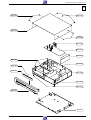
Gehäuseoberteil
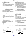
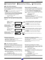
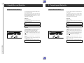
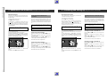
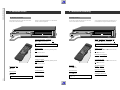
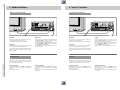
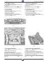
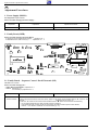
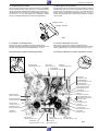
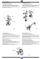
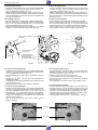
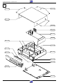
– 6 Schrauben A herausdrehen und Schraube A (Fig. 1) lösen.
Hinweis: Die Schraube A ist zur "VDE-Sicherheit" mit einer
Sicherungsscheibe an der Haube befestigt und nicht abnehmbar.
– Seitenteile des Gehäuseoberteils vorsichtig etwas auseinanderziehen und dabei Gehäuseoberteil ca. 3cm nach hinten schieben
und abnehmen.
Cabinet Upper Part
– Undo 6 screws A and loosen screw A (Fig. 1).
Note: For reasons of "VDE safety" the screw A is fastened with a
retaining washer to the upper part of the cabinet and cannot be
removed.
– Pressing the side panels carefully apart push the upper part of the
cabinet towards the rear by approx. 3cm and remove it.
Bodenblech
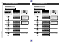
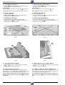
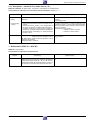
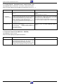
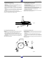
– Rastnasen B lösen (Fig. 2) und Bodenblech abnehmen.
Bottom Panel
– Release the locking lugs B (Fig. 2) and remove the bottom panel.
Frontblende
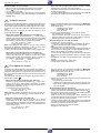
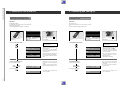
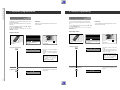
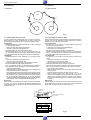
– Schraube C (Fig. 3) herausdrehen.
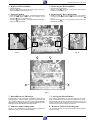
– Rasthaken D (Fig. 3) sowie Rasthaken E (Fig. 2) lösen und
Frontblende abnehmen.
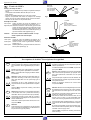
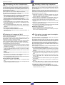
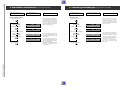
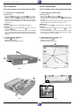
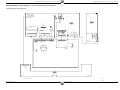
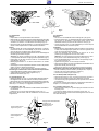
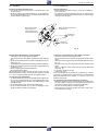
Hinweis zum Zusammenbau: Beim Aufstecken der Frontblende
von vorne auf das Gerät ist die Cassettenklappe so nach innen zu
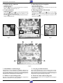
drücken, daß der Hebel in die Führung (Fig. 4) der Cassettenklappe
eintaucht.
Front Panel
– Undo the screw C
– Release the locking catches D (Fig.3) and the catch E (Fig. 2)
and remove the front panel.
Note: When attaching the front panel from the from to the video
recorder press the cassette lid inwards so that the lever engages
with the guide (Fig.4) of the cassette lid.
2. Bedieneinheit ausbauen
2. Removing the Keyboard Unit
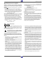
– Rastnasen F lösen (Fig. 5).
– Bedieneinheit abnehmen.
– Gegebenenfalls Steckverbindung lösen.
– Release the locking lugs F (Fig. 5).
– Withdraw the Keyboard Unit.
– Unplug the connector if necessary.
E
A
B
A
A
A
Fig. 1
Fig. 2
C
D
D
D
Fig. 3
GRUNDIG Service-Technik
Fig. 4
1 - 29