1
SERVICE MANUAL
*
Service
Manual
GV 400, GV 402
GV 410, GV 412
GV 430
MV 4005, MV 4105
GV 400 OST, GV 411 OST
Sach-Nr./Part no.
72010-514.80
GV 400
GV 402
GV 410
GV 412
(77400-010.51 / G.MD 0200) RP 10
(77400-012.51 / G.MD 0900) RP 13
(77400-110.51 / G.MD 1400) RP 10
(77400-111.51 / G.MD 1900) RP 13
GV 430
MV 4005
MV 4105
(77400-310.51 / G.MD 2600) RP 13
(77400-044.51 / M.MD 0800) RP 10
(77400-144.51 / M.MD 1700) RP 13
GV 400 OST
(77400-013.51 / G.MD 5600) RT130
GV 411 OST
(77400-112.51 / G.MD 5700) RT 230
RP 10 / RT 130
Änderungen vorbehalten
Subject to alteration
RP 13 / RT 230
PAL
Printed in Germany
VK 222 0793
SECAM OST
Service Manual Sach-Nr. 72010-514.80
Service Manual Part No. 72010-514.80
Allgemeiner Teil / General
D
GB
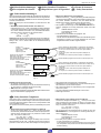
Inhaltsverzeichnis
Table of contents
Seite
Page
Allgemeiner Teil ................................. 1-1…1-38
General ............................................... 1-1…1-38
Geräteübersicht ........................................................................... 1-3
Meßgeräte / Meßmittel ................................................................. 1-4
Technische Daten ........................................................................ 1-4
Chip-Technologie ......................................................................... 1-5
Sicherheitsvorschriften ................................................................. 1-6
Sicherheitsbestimmungen ............................................................ 1-7
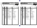
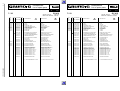
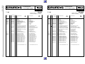
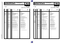
Abkürzungen .............................................................................. 1-11
Bedienelemente ......................................................................... 1-12
Servicehinweise ......................................................................... 1-29
Servicetestprogramm ................................................................. 1-35
Video Recorder Overview ............................................................ 1-3
Test Equipment / Jigs .................................................................. 1-4
Specifications ............................................................................... 1-4
Chip Technology .......................................................................... 1-5
Safety Requirements ................................................................... 1-6
Safety Standard Requirements .................................................... 1-7
Abbreviations ............................................................................. 1-11
General Notes ............................................................................ 1-12
Service instructions .................................................................... 1-29
Servicetestprogram .................................................................... 1-35
Beschreibungen .................................... 2-1…2-8
Descriptions .......................................... 2-1…2-8
Netzteil (MSM1) ...........................................................................
Chassisplatte (MFB) ....................................................................
• Ablaufsteuerung / Deckelektronik (DE) ....................................
• Empfangseinheit (FV) .............................................................
• Video / Chroma, In / Out (VSIO) .............................................
• Standardton / Audio Linear (AL) ...............................................
Bedieneinheit ...............................................................................
Power Supply (MSM1) .................................................................
Family Board (MFB) .....................................................................
• Sequence Control / Deckelectronic (DE) ..................................
• Frontend (FV) ............................................................................
• Video / Chroma, In / Out (VSIO) ...............................................
• Standard Sound / Audio Linear (AL) .........................................
Keyboard Control Unit ..................................................................
2-1
2-1
2-1
2-4
2-5
2-7
2-8
2-1
2-1
2-1
2-4
2-5
2-7
2-8
Abgleich ................................................ 3-1…3-3
Adjustment Procedures ....................... 3-4…3-6
Netzteil (MSM1) ...........................................................................
Chassisplatte (MFB) ....................................................................
• Ablaufsteuerung / Deckelektronik (DE) .....................................
• Empfangseinheit (FV) ..............................................................
• Video / Chroma (VS) ................................................................
• Standardton / Audio Linear (AL) ...............................................
Bedieneinheit ...............................................................................
Power Supply (MSM1) .................................................................
Family Board (MFB) .....................................................................
• Sequence Control / Deckelectronic (DE) ..................................
• Frontend (FV) ............................................................................
• Video / Chroma (VS) .................................................................
• Standard Sound / Audio Linear (AL) .........................................
Keyboard Control Unit ..................................................................
3-1
3-1
3-1
3-2
3-2
3-3
3-3
3-4
3-4
3-4
3-5
3-5
3-6
3-6
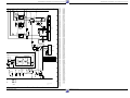
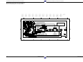
Platinenabbildungen
und Schaltpläne ................................. 4-1…4-22
Layout of the P.C.B.
and Circuit Diagrams .......................... 4-1…4-2
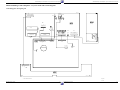
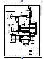
Verdrahtungsplan ......................................................................... 4-1
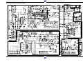
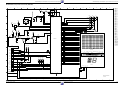
Blockschaltplan (Analog) ............................................................. 4-2
Blockschaltplan (Digital) ............................................................... 4-3
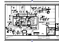
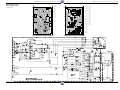
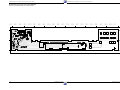
Netzteil (MSM1) ........................................................................... 4-4
Laufwerkplatte – Sensoreneinheit ................................................ 4-9
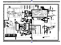
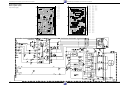
Chassisplatte (MFB) .................................................................... 4-6
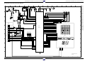
• Ablaufsteuerung / Deckelektronik (DE) .................................... 4-8
• Empfangseinheit (FV) ........................................................... 4-11
• Video / Chroma, In / Out (VS) ............................................... 4-12
• Standardton / Audio Linear (AL) ............................................. 4-14
Kopfverstärker (LHA) ............................................................... 4-15
Bedieneinheit (MDCG1) ............................................................ 4-17
Bedieneinheit (MDCB1) ............................................................ 4-19
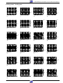
Oszillogramme ........................................................................... 4-21
Wiring Diagram ............................................................................ 4-1
Block Circuit Diagram (Analog) .................................................... 4-2
Block Circuit Diagram (Digital) ..................................................... 4-3
Power Supply (MSM1) ................................................................. 4-4
Tape Deck Sensor Panel ............................................................. 4-9
Family Board (MFB) ..................................................................... 4-6
• Sequence Control / Deckelectronic (DE) .................................. 4-8
• Frontend (FV) .......................................................................... 4-11
• Video / Chroma, In / Out (VS) ................................................. 4-12
• Standard Sound / Audio Linear (AL) ....................................... 4-14
Head Amplifier (LHA) ................................................................. 4-15
Keyboard Control Unit (MDCG1) ............................................... 4-17
Keyboard Control Unit (MDCB1) ................................................ 4-19
Oscillograms .............................................................................. 4-21
Laufwerk ............................................ 5-1…5-10
Drive Mechanism ............................... 5-1…5-10
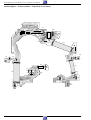
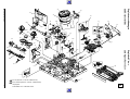
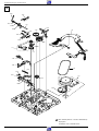
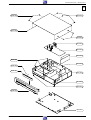
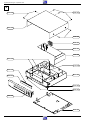
Explosionszeichnungen
und Ersatzteilliste .............................. 6-1…6-26
Exploded Views and
Spare Parts List ................................. 6-1…6-26
1-2
GRUNDIG Service-Technik
GRUNDIG Service-Technik
Kopfverstärker / Head Amplifier (2-Kopf/Head)
Kopfverstärker / Head Amplifier (3-Kopf/Head)
Kopfverstärker / Head Amplifier (4-Kopf/Head)
Bedieneinheit / Keyboard Control Unit (MDCG1)
Bedieneinheit / Keyboard Control Unit (MDCB1)
27599-001.01
27599-004.00
27599-004.01
27599-004.02
27599-002.00
27599-002.14
RT230
RP13
RT130
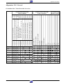
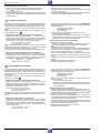
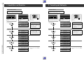
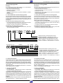
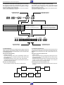
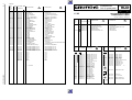
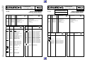
Geräte-Feature-Übersicht
Table of Features
RP10
VISS
6 Timer
VPS
4-Kopf/Head (NP/LP)
3-Kopf/Head
2-Kopf/Head
VST-Abstimmung/Tuning system
S./P 4-19
S./P 4-17
S./P 4-16
S./P 4-15
S./P 4-15
Geräte-Bausteinübersicht
Table of Moduls
CCIR, DK - PAL/SECAM
CCIR, B/G/H - PAL
27599-001.11
Chassisplatte / Family Board (MFB)
S./P 4-6
• Ablaufsteuerung / Sequence Control/Deckelectonic (DE) S./P 4-8
• Empfangseinheit / Frontend (FV)
S./P 4-11
• Video/Chroma / In/Out (VSIO)
S./P 4-12
• Standardton / Standard Sound - Audio Linear (AL)
S./P 4-14
27599-001.00
S./P 4-9
Laufwerkplatte-Sensoreneinheit / Tape Deck Sensor Print
75988-001.18
S./P 4-4
Netzteil / Power Supply (MSM1)
27599-003.00
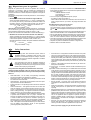
Allgemeiner Teil / General
Allgemeiner Teil / General
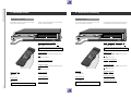
Geräteübersicht / Video Reocorder Overview
Fernbedienung
Remote Control
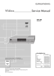
GV 400
GV 402
GV 410
GV 412
GV 430
MV 4005
MV 4105
GV 400 OST
GV 411 OST
1-3
Allgemeiner Teil / General
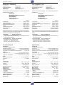
Meßgeräte / Meßmittel
Test equipment / aids
Regeltrenntrafo
Zweikanaloszilloskop
Digitalmultimeter
Millivoltmeter
Variable isolating transformer
Dual channel oscilloscope
Digital multimeter
Millivoltmeter
Farbgenerator
Tongenerator
Stabilisiertes Netzgerät
Frequenzzähler
Beachten Sie bitte das Grundig Meßtechnik-Programm, das Sie unter
folgender Adresse erhalten:
Grundig AG
Geschäftsbereich Industrieelektronik
Würzburger Str. 150
90766 Fürth/Bay.
Tel.0911/7330-0
Telefax 0911/7330-479
Colour generator
AF Generator
Stabilized power supply
Frequency counter
Please note the Grundig Catalog "Test and Measuring Equipment"
obtainable from:
Grundig AG
Geschäftsbereich Industrieelektronik
Würzburger Str. 150
90766 Fürth/Bay.
Tel.0911/7330-0
Telefax 0911/7330-479
Sach-Nr
Testcassette .............................................................. 9.27540 - 1011
Testcassette (HiFi) .................................................... 9.27540 - 1016
Bandzug-Einstellgriff und stift ................................... 75988 - 002.27
Drehmomentmesser 600gf-cm ................................. 75987 - 262.72
Adapter ..................................................................... 75987 - 262.73
Einstellschraubendreher ........................................... 75987 - 262.80
Nylonhandschuhe ....................................................... handelsüblich
Tentelometel ............................................................... handelsüblich
Part no
Test cassette ............................................................. 9.27540 - 1011
Test cassette (HiFi) ................................................... 9.27540 - 1016
Tape tension adjustment tool - handle and - pin ....... 75988 - 002.27
Torquemeter ............................................................. 75987 - 262.72
Adapter ..................................................................... 75987 - 262.73
Adjustment screw driver ............................................ 75987 - 262.80
Nylon gloves ...................................................... commonly available
Tentelometer ...................................................... commonly available
Diese Meßmittel können Sie über die Serviceorganisation beziehen.
Wir weisen jedoch darauf hin, daß es sich hierbei z.T. um Meßmittel
handelt, die am Markt bereits eingeführt sind.
You can order these test equipments from the Service organization.We
refer to you that these test equipments are already obtainable on the
market.
Testcassette
Sach-Nr. 9.27540-1011
• Farbtestbild mit Dropout-Einblendung
• 6,3kHz- Senkrecht-Vollspuraufzeichnung und Bezugspegel 333Hz
in dreiminütigem Wechsel.
Test cassette
Part no. 9.27540-1011
• Colour test pattern with dropout recording
• 6.3kHz vertical full-track recording alternating with 333Hz reference
level every 3 minutes.
Testcassette (HiFi)
Sach-Nr. 9.27540-1016
• Farbtestbild mit Dropout-Einblendung
• Längsspur - Ton: 6,3kHz und 333Hz
• FM - Ton: 1kHz Vollpegel (± 50kHz Hub)
Test cassette (HiFi) Part no. 9.27540-1016
• Colour test pattern with dropout recording
• Longitudinal track sound: 6.3kHz and 333Hz
• FM sound: 1kHz full level (± 50kHz deviation)
Technische Daten
Specification
VHS-System
1/2” Video - Cassettenrecorder
Bandgeschwindigkeit .............................. 2.339cm/s (Standard play)
Aufzeichnungsgeschwindigkeit ................... 4.84m/s (Standard play)
Umspulzeit bei Vor-/Rücklauf mit E180-Cassette: .......... typisch 95s
VHS-System
1/2” video cassette recorder
Tape speed ............................................. 2.339cm/s (Standard play)
Head to tape speed ..................................... 4.84m/s (Standard play)
Winding time or forward wind/rewind of a E180 Cassette: typically 95s
FS-Norm
CCIR, B/G/H - PAL .................................. GV 400, GV 402, GV 410,
............................................... GV 412, GV 430, MV 4005, MV 4105
CCIR, D/K - PAL/SECAM ...................... GV 400 OST, GV 411 OST
TV standard
CCIR, B/G/H - PAL .................................. GV 400, GV 402, GV 410,
............................................... GV 412, GV 430, MV 4005, MV 4105
CCIR, D/K - PAL/SECAM ...................... GV 400 OST, GV 411 OST
Video
Signal / Rauschabstand .................................. ≥ 48 ±3dB (weighted)
Video
Signal / noise ratio .......................................... ≥ 48 ±3dB (weighted)
Auflösung ........................................................................... ca. 3MHz
Video resolution .......................................................... approx. 3MHz
Ton
Frequenzgang
Standard play: .................................................... 80Hz…10kHz ≤8dB
Longplay: ............................................................. 80Hz…5kHz ≤8dB
Sound
Frequency response
Standard play: .................................................... 80Hz…10kHz ≤8dB
Longplay: ............................................................. 80Hz…5kHz ≤8dB
Störabstand .......................................................... ≥ 43dB (weighted)
Signal / noise ratio ............................................... ≥ 43dB (weighted)
Gleichlaufschwankung ....................................... ≤ 0.5% (DIN 45507)
Wow and flutter .................................................. ≤ 0.5% (DIN 45507)
Netzspannung ......................................................... 220V~…240V~
Netzfrequenz ................................................................... 45…65Hz
Leistungsaufnahme
- Aufnahme .......................................................................... ca. 14W
- EE-Betrieb ......................................................................... ca. 10W
- Stand by (Modulator aus) ................................................. ca. 9,5W
Mains voltage .......................................................... 220V~…240V~
Mains frequency .............................................................. 45…65Hz
Power consumption
- Record ........................................................................ approx. 14W
- EE mode ..................................................................... approx. 10W
- Stand by mode (Modulator off) .................................. approx. 9,5W
Umgebungstemperatur ........................................... +10°C…+35°C
Relative Luftfeuchte .............................................................. ≤ 80%
Betriebslage ..................................................................... horizontal
Ambient temperature ............................................. +10°C … +35°C
Relative humidity .................................................................. ≤ 80%
Operating position ........................................................... horizontal
1-4
GRUNDIG Service-Technik
Allgemeiner Teil / General
D
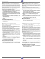
CHIP Technik
GB
CHIP Technology
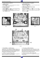
Aus- und Einlöten von CHIP-Bauteilen
- Verwenden Sie nur einen Niedervoltlötkolben mit Temperaturregelung.
- Die Löttemperatur sollte ca. 240 °C betragen (max. 300 °C).
- Halten Sie die Lötzeit so kurz wie möglich.
- Belassen Sie CHIP-Bauteile bis zur Bearbeitung in der Originalverpackung. Damit wird die Oxidation der Stirnkontakte vermieden.
- Berühren Sie CHIP- Bauteile nicht mit der bloßen Hand.
Soldering and unsoldering of CHIP components
- Use only low-voltage soldering irons with temperature control.
- Permissible soldering temperatures are approx. 240 °C up to max.
300 °C.
- Keep the soldering period as short as possible.
- Keep the CHIP components in their original packages until they are
used to avoid oxidation of the end contacts.
- Do not touch CHIP components with bare hands.
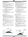
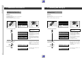
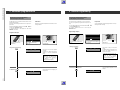
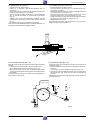
Auslöten von CHIP-Bauteilen
1. Schritt: CHIP- Lötstelle mit Sauglitze absaugen (Fig. 1).
2. Schritt: CHIP-Enden, bzw. das komplette CHIP-Bauteil erwärmen.
CHIP von der Klebung ohne Kraftaufwand abdrehen, damit
unter dem CHIP liegende Leiterbahnen nicht abgerissen
werden (Fig. 2).
Unsoldering of CHIP components
1. step: Clean the CHIP soldering point with a solder wick (Fig. 1).
2. step: Warm up the ends of the CHIP or the whole CHIP component
and remove the CHIP from the adhesive by turning it without
application of force so that the tracks beneath the CHIP do not
break (Fig. 2).
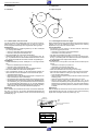
Achtung!
Attention! Do not use unsoldered CHIPS any more!
The conductive layer may be broken.
Ausgelötetes CHIP nicht wiederverwenden!
Die leitende Schicht kann ausgebrochen sein.
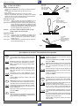
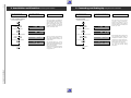
Einlöten von CHIP-Bauteilen
3. Schritt: Lötpunkt von Lötrückständen säubern.
Lötperle anbringen (Fig. 3).
4. Schritt: CHIP an der Lötstelle ansetzen, zentrieren und anlöten
(Fig. 4).
5. Schritt: Freie Seite löten. Nach dem Erkalten die erste Lötstelle
nochmals nachlöten (Fig. 5).
I
Tecnica CHIP
Soldering of CHIP components
3. step: Remove possible residues from the soldering point.
Then apply a solder bead (Fig. 3).
4. step: Put the CHIP onto the soldering point, then center and fix it
(Fig. 4).
5. step: Solder the free end of the CHIP and resolder the first soldering
point after it has cooled (Fig. 5).
F
Saldatura e dissaldatura di componenti MOS
- Impiegare un saldatore a basso voltaggio con regolazione della
temperatura.
- Temperatura del saldatore: ca. 240 °C (valore massimo 300 °C).
- Il tempo di saldatura deve essere il più breve possibile.
- Il componente CHIP deve rimanere nell´imballaggio originale fino al
momento del suo impiego per evitare che le superfici di contatto si
ossidino.
- Non toccare i componenti CHIP con mani nude.
Dissaldatura di un CHIP
1. Aspirare i punti di saldatura del CHIP con una calza dissaldante
(Fig. 1).
2. Riscaldare le superfici di contatto del CHIP risp. te tutto il CHIP e
staccarlo con cautela. Attenzione a non esercitare for za per non
danneggiare le piste sottostanti (Fig. 2).
Attenzione! Non impiegare più il CHIP dissaldato, perchè il
corpo elettrico può presentare delle rotture.
Technologie CMS
Soudure des composants CMS
- Utiliser exclusivement un fer à souder à basse tension et réglage
thermique
- La température de soudure doit être de 240 OC environ
(max. 300 OC)
- L´opération doit être très brève.
- Conserver les composants CMS dans leur emballage d´origine
jusqu´au moment de leur utilisation, ceci pour éviter l´oxydation
des contacts externes.
- Ne pas toucher les composants CMS à la main nue.
Dessoudage des composants CMS
1. Aspirer la soudure du composant CMS à l'aide de la tresse à
souder (Fig. 1).
2. Chauffer légèrement les contacts externes du composant CMS
ou le composant lui-même. Retirer ce dernier avec précaution en
le tournant afin d´évìter un arrachement des circuits imprimés
situés sous le composant (Fig. 2).
Attention!
Saldatura di un CHIP
3. Pulire il punto dai residui di saldatura. Applicare una goccia di stagno
(Fig. 3).
4. Appoggiare il CHIP sul punto di saldatura, centrarlo e quindi saldarlo
(Fig. 4).
5. Saldare la superfici di contatto libera e, dopo che questa si è
raffreddata, saldare nuovamente la superfici opposta (Fig. 5).
Lötzinn
Solder
Stagno
Soudure
Estaño
Chip
Composant CMS
Leiterplatte
P.C.B.
Piastra stampata
Circuit imprimé
Placa de circuito impreso
Fig. 1
GRUNDIG Service-Technik
Ne pas réutiliser les composants CMS, la face
conductrice pouvant être endommagée.
Soudure des composants CMS
3. Aspirer les restes de soudure sur le circuit. Poser une pointe de
soudure (Fig. 3).
4. Poser le composant CMS sur cette pointe de soudure, centrer et
souder. Maintenir le composant CMS à l´aide d´une pince (Fig. 4).
5. Effectuer la même opération pour l'autre côté. Terminer la première soudure (Fig. 5).
Lötkolbenspitze
Tip of soldering iron
Punta saldatore
Panne du fer à souder
Punto de soldator
Pinzette
Tweezers
Pinzetta
Pince brucelle
Pinzas
Lötkolbenspitze
Tip of soldering iron
Punta saldatore
Panne du fer à souder
Punto de soldator
Kleber
Adhesive
Adesivo
Adhesif
Pegamento
Fig. 2
1-5
Allgemeiner Teil / General
Técnica de CHIP´s
E
Soldaje y desoldaje de CHIP´s
- Emplear sólo un soldador de bajo voltaje con regulación de temperatura.
- La temperatura del soldador debe ser de aprox. 240 °C
(máx. 300 °C).
- El tiempo de soldadura debe de ser lo más corto posible.
- Dejar los componentes CHIP hasta su montaje en el embalaje
original. Con ello se evita la oxidación de los contactos frontales.
- No tocar con las manos los componentes CHIP.
Fixierpunkt
Fixing point
Punto di fissaggio
Point de soudure
Punto de fijación
Fig. 3
1. Lötstelle
Joint 1
Punto di saldatura 1
Point de soudure 1
Primer punto de soldadura
Desoldaje de un CHIP
Primer paso: Aspirar el estaño del punto de soldadura con un
aspirador de los tipos de pera o de resorte (Fig. 1).
Segundo paso: Calentar los extremos o todo el CHIP y girarlo con las
pinzas. No hacer fuerza para que la placa de circuito
impreso no resulte dañada. Cuidar de que las pistas
situadas debajo del CHIP no se suelten de la placa, ya
que éstas también están pegadas (Fig. 2).
Ciudado!
Lötzinn
Solder
Stagno
Soudure
Estaño
No volver a utilizar el CHIP desoldado. La capa
eléctrica puede estar interrumpida.
Soldadura de CHIP´s
Tercer paso: Limpiar el punto de soldadura de residuos de la
soldadura anterior. Poner una gota de estaño (Fig. 3).
Cuarto paso: Colocar el CHIP sobre la gota estaño, centrarlo y
soldarlo (Fig. 4).
Quinto paso: Soldar la parte libre y, después enfriarse, soldar también la parte opuesta (Fig. 5).
Fig. 4
2. Lötstelle
Joint 2
Punto di saldatura 2
Point de soudure 2
Segundo punto de
soldadura
Fig. 5
Sicherheitsvorschriften / Safety requirements / Prescrizioni de sicurezza /
Prescriptions de sécurité / Prescripciones de seguridad
Achtung: Bei Eingriffen ins Gerät sind die Sicherheitsvorschriften nach VDE 0701 (reparaturbezogen)
bzw. VDE 0860 / IEC 65 (gerätebezogen) zu beachten!
D
!
V
DE
!
!
V
DE
Attention: Please observe the applicable safety requirements according to VDE 0701 (concerning repairs) and VDE 0860 / IEC 65 (concerning type of
product)!
Attenzione: Osservarne le corrispondenti prescrizioni di sicurezza VDE 0701 (concernente servizio) e
VDE 0860 / IEC 65 (concernente il tipo di prodotto)!
I
!
V
DE
!
V
DE
Attention:
Prière d'observer les prescriptions de sécurité VDE
0701 (concernant les réparations) et VDE 0860 / IEC
65 (concernant le type de produit)!
Componentes que cumplen las normas VDE/IEC. En
caso de sustitución, emplear componentes con idénticas especificaciones!
Durante la reparacion observar las normas sobre
componentes MOS!
USA
U.S. &
Canada
!
Componenti secondo le norme VDE risp. te IEC! In
caso di sostituzione impiegare solo componenti con le
stesse caratteristiche.
Osservare le relative prescrizioni durante, lavori con
componenti MOS!
F
Atención: Recomendamos las normas de seguridad
VDE u otras normas equivalentes, por ejemplo: VDE
0701 para reparaciones, VDE 0860 / IEC 65 para
aparatos!
E
Components to IEC or VDE guidelines! Only use
components with the same specifications for replacement!
Observe MOS components handling instructions
when servicing!
Composants répondant aux normes VDE ou IEC. Les
remplacer uniquement par des composants ayant les
mêmes spécifications.
Lors de la manipulation des circuits MOS, respecter les
pescriptions MOS!
Bauteile nach IEC- bzw. VDE-Richtlinien ! Im Ersatzfall nur Teile mit gleicher Spezifikation verwenden!
MOS - Vorschriften beim Umgang mit MOS - Bauteilen beachten!
GB
V
DE
!
V
DE
Attention: Because of autovoltage facility this set can
be operated from AC mains from 180 - 240V, 50/60Hz.
Also observe the information given on the rear of the
set.
CAUTION-for continued protection against risk of fire
replace only with same type of fuses!
CAUTION: to reduce the risk of electric shock, do not
remove cover (or back), no user-serviceable parts
inside, refer servicing to qualified service personnel.
Components to safety guidelines (IEC/U.L.)! Only use
com-ponents with the same specifications for replacement!
By checking the leakage current and insulation resistance ensure that the exposed parts are acceptably
insulated from the supply circuit.
Observe MOS components handling instructions
when servicing!
1-6
GRUNDIG Service-Technik
Allgemeiner Teil / General
D
F
D
Sicherheitsbestimmungen
Prescriptions de sécurité
GB
E
Safety Standard Compliance
Disposiciones para la seguridad
I
USA
Norme di sicurezza
Safety Instructions
Sicherheitsbestimmungen
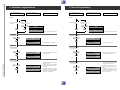
Nach Servicearbeiten ist bei Geräten der Schutzklasse II die Messung
des Isolationswiderstandes und des Ableitstromes bei eingeschaltetem Gerät nach VDE 0701 / Teil 200 bzw. der am Aufstellort geltenden
Vorschrift, durchzuführen!
Dieses Gerät entspricht der Schutzklasse II, erkennbar durch das
Symbol
.
• Messen des Isolationswiderstandes nach VDE 0701.
Isolationsmesser (UTest = 500V-) gleichzeitig an beiden Netzpolen
und zwischen allen Gehäuse- oder Funktionsteilen (Antenne, Buchsen, Tasten, Zierteilen, Schrauben, usw.) aus Metall oder Metallegierungen anlegen. Fehlerfrei ist das Gerät bei einem:
RIsol ≥ 2MΩ bei UTest = 500VMeßzeit: ≥ 1s (Fig. 1)
Anmerkung: Bei Geräten der Schutzklasse II kann durch Entladungswiderstände der Meßwert des Isolationswiderstandes konstruktionsbedingt < 2MΩ sein. In diesen Fällen ist die Ableitstrommessung
maßgebend.
Prüfling
Test item
Apparecchio in misura
Pièce d'essai
Aparato de prueba
Netzstecker des Prüflings
Mains plug of test item
Spina di rete dell´apparecchio in misura
Fiche secteur pièce d'essai
Clavija de red del aparato de prueba
Prüfling
Test item
Apparecchio in misura
Pièce d'essai
Aparato de prueba
Netzstecker des Prüflings
Mains plug of test item
Spina di rete dell´apparecchio in misura
Fiche secteur pièce d'essai
Clavija de red del aparato de prueba
• Messen des Ableitstromes nach VDE 0701.
Ableitstrommesser (UTest =220V≈) gleichzeitig an beiden Netzpolen
und zwischen allen Gehäuse- oder Funktionsteilen (Antenne, Buchsen, Tasten, Zierteilen, Schrauben, usw.) aus Metall oder Metallegierungen anlegen. Fehlerfrei ist das Gerät bei einem:
IAbleit ≤ 1mA bei UTest = 220V ≈ / Meßzeit ≥ 1s (Fig. 2)
• Wir empfehlen die Messungen mit dem METRATESTER 4 durchzuführen. (Meßgerät zur Prüfung elektrischer Geräte nach VDE
0701).
ABB METRAWATT GmbH
Thomas-Mann-Str. 16-20
90471 Nürnberg
• Ist die Sicherheit des Gerätes nicht gegeben, weil
- eine Instandsetzung unmöglich ist,
- oder der Wunsch des Benützers besteht, die Instandsetzung nicht
durchführen zu lassen, so muß dem Betreiber die vom Gerät
ausgehende Gefahr schriftlich mitgeteilt werden.
Mit der Greifklemme alle Metallteile u. metallisierten Teile abtasten.
All metal and metallised parts must be tested with the Caliper clamp.
Con cavo provvisto di morsetto toccare tutte le parti metalliche o
metallizzate.
A l´aide d´une pince vérifier toutes les parties métalliques ou
métallisées.
Con la pinza, tocar todas las piezas metálicas o metalizadas.
MΩ
MΩ
METRATESTER 4
Netzstecker/Mains plug/Spina di rete/Fiche secteur/Clavija de red
Fig. 1
Mit der Greifklemme alle Metallteile u. metallisierten Teile abtasten.
All metal and metallised parts must be tested with the Caliper clamp.
Con cavo provvisto di morsetto toccare tutte le parti metalliche o
metallizzate.
A l´aide d´une pince vérifier toutes les parties métalliques ou
métallisées.
Con la pinza, tocar todas las piezas metálicas o metalizadas.
mA
mA
METRATESTER 4
Netzstecker/Mains plug/Spina di rete/Fiche secteur/Clavija de red
Fig. 2
Empfehlungen für den Servicefall
• Nur Original - Ersatzteile verwenden.
Bei Bauteilen oder Baugruppen mit der Sicherheitskennzeichnung
! sind Original - Ersatzteile zwingend notwendig.
• Auf Sollwert der Sicherungen achten.
Zur Sicherheit beitragende Teile des Gerätes dürfen weder beschädigt noch offensichtlich ungeeignet sein.
GB
• Dies gilt besonders für Isolierungen und Isolierteile.
• Netzleitungen und Anschlußleitungen sind auf äußere Mängel vor
dem Anschluß zu prüfen. Isolation prüfen!
• Die Funktionssicherheit der Zugentlastung und von BiegeschutzTüllen ist zu prüfen.
• Thermisch belastete Lötstellen absaugen und neu löten.
• Belüftungen frei lassen.
Safety Standard Compliance
After service work on a product conforming to the Safety Class II, the
insulating resistance and the leakage current with the product switched
on must be checked according to VDE 0701 or to the specification valid
at the installation location!
This product conforms to the Safety Class II, as identified by the symbol
.
• Measurement of the Insulation Resistance to VDE 0701,
Connect an Insulation Meter (UTest = 500V-) to both mains poles
simultaneously and between all cabinet or functional parts (antenna,
sockets, buttons, decorative parts, etc.) made from metal or metal
alloy. The product is fault free if:
RIsol ≥ 2MΩ at UTest = 500VMeasuring time: ≥ 1s, (Fig. 1)
Comment: On products conforming to the Safety Class II the Insulation Resistance can be < 2MΩ, dependent constructively on discharge resistors. In this case, the check of the leakage current is significant.
GRUNDIG Service-Technik
• Measurement of the Leakage Current to VDE 0701.
Connect the Leakage Current Meter (UTest = 220V≈) to both mains
poles simultaneously and between all cabinet or functional parts
(antenna, sockets, buttons, screws, etc.) made from metal or metal
alloy. The product is fault free if:
ILeak ≤ 1mA at UTest = 220V ≈
Measuring time: ≥ 1s, (Fig. 2)
• We recommend that the measurements be carried out using the
METRATESTER 4. (Test equipment for checking electrical products to VDE 0701).
ABB METRAWATT GmbH
Thomas-Mann-Str. 16-20
90471 Nürnberg
• If the safety of the product is not proved, because
- a repair and restoration is impossible
- or the request of the user is that the restoration is not to be carried
out, the operator of the product must be warned of the danger by
a written warning.
1-7
Allgemeiner Teil / General
Recommendation for service repairs
• With components or assemblies accompanied with the Safety
Symbol ! only original spare parts are strictly to be used.
• Use only original fuse value.
• Parts contributing to the safety of the product must not be damaged
or obviously unsuitable. This is valid especially for insulators and
insulating parts.
I
Norme di sicurezza
Successivamente ai lavori di riparazione, negli apparecchi della classe
di protezione II occorre effettuare la misura della resistenza di isolamento e della corrente di dispersione quando l’apparecchio e’acceso,
secondo le norme VDE 0701 / parte 200 e rispettivamente le norme
locali!
Questo apparecchio corrisponde alla classe di protezione II ed è
riconoscibile dal simbolo
.
M
M
• Misura della resistenza di isolamento secondo VDE 0701
Applicare il misuratore di isolamento (tens. prova = 500V-) contemporaneamente ai due poli di rete e tra tutte le parti del mobile e delle
funzioni (antenna, prese, tasti, mascherine, viti ecc.) in metallo o in
lega metallica. L’apparecchio non presenta difetti quando:
Risol ≥ 2MΩ con tens.prova = 500VTempo di misura: ≥ 1s (Fig. 1).
Nota: Negli apparecchi della classe II, che per motivi costruttivi
dispongono di resistenze di dispersione, il valore di misura della
resistenza di isolamento può essere inferiore a < 2MΩ.
In questi casi è determinante la misura della corrente di dispersione.
• Misura della corrente di dispersione secondo VDE 0701
Applicare il misuratore di isolamento (tens. prova = 220V≈) contemporaneamente ai due poli di rete e tra tutte le parti del mobile e delle
funzioni ( antenna, prese, tasti, mascherine, viti ecc.) in metallo o in
lega matallica. L’apparecchio non presenta difetti quando:
Idisp. ≤ 1mA con tens. prova = 220V≈
Tempo di misura : ≥ 1s (Fig. 2)
F
• Si raccomanda di effettuare le misure con lo strumento METRATESTER 4 (strumento di misura per il controllo di apparecchi elettrici
secondo VDE 0701).
ABB METRAWATT GmbH
Thomas-Mann-Str. 16-20
90471 Nürnberg
• Se la sicurezza dell’apparecchio non è raggiunta, perchè
- una riparazione non è possibile
- oppure è desiderio del cliente che una riparaz. non avvenga in
questi casi si deve comunicare per iscritto all’utilizzat. la pericolosità dell’apparecchio riguardo il suo isolamento.
Raccomandazione per il servizio assistenza
• Impiegare solo componenti originali:
I componenti o i gruppi di componenti contraddistinti dall’ indicaz.
! devono assolutamente venir sostituiti con parti originale.
• Osservare il valore nominale dei fusibili.
I componenti che concorrono alla sicurezza dell´apparecchio non
possono essere nè danneggiati nè risultare visibilmente inadatti.
Questo vale soprattutto per isolamenti e parti isolate.
• I cavi di rete e di collegamento vanno controllati prima dell’utilizzo
affinchè non presentino imperfezioni esteriori. Controllare l’isolamento.
• E´necessario controllare la sicurezza dei fermacavi e delle guaine
flessibili.
• Saldature caricate termicam. vanno rifatte.
• Lasciare libere le fessure di areazione.
Prescriptions de sécurité
Suite aux travaux de maintenance sur les appareils de la classe II, il
convient de mesurer la résistance d’isolement et le courant de fuite sur
l’appareil en état de marche, conformément à la norme VDE 0701 §
200, ou selon les prescriptions en vigueur sur le lieu de fonctionnement
de l’appareil!
Cet appareil est conforme aux prescriptions de sécurité classe II,
signalé par le symbole
.
• Mesure de la résistance d'isolement selon VDE 0701
Brancher un appareil de mesure d’isolation (Utest = 500V-) simultanément sur les deux pôles secteur et entre toutes les parties
métalliques ou métallisées accessibles de l’appareil (antenne, embases, touches, enjoliveurs, vis, etc.).
Le fonctionnement est correct lorsque:
Risol ≥ 2MΩ pour une Utest = 500VDurée de la mesure: ≥ 1s
Observations: L’isolation des appareils de la classe II, de part leur
conception (résistances de décharge), peut être inférieure à 2MΩ,
(Fig. 1).
• Mesure du courant de fuite selon VDE 0701
Brancher un ampèremètre du courant de fuite (Utest = 220V≈)
simultanément sur les deux pôles du secteur et entre toutes les
parties métalliques ou métallisées accessibles de l’appareil (antenne, embases, touches, enjoliveurs, vis, etc.). Le fonctionnement est
correct lorsque (Fig. 2):
Ifuite ≤ 1mA pour Utest = 220V≈
Durée de la mesure: ≥ 1s.
1-8
• Mains leads and connecting leads should be checked for external
damage before connection. Check the insulation!
• The tension relief and bending protection bushes are to be checked
for their functional safety.
• Thermally loaded solder pads are to be sucked off and re-soldered.
Ensure that the ventilation slots are not obstructed.
Pour ces mesures, nous préconisons l´utilisation du METRATESTER 4 (instrument de mesure pour le contrôle d’appareils électriques conformes à la norme VDE 0701).
ABB METRAWATT GmbH
Thomas-Mann-Str. 16-20
90471 Nürnberg
• Dans le cas où la sécurité de l’appareil n´est pas assurée pour les
raisons suivantes:
- la remise en état est impossible
- l’utilisateur ne souhaîte pas la remise en état de l’appareil, l'utilisateur doit être informé par écrit du danger que représente l'utilisation de l’appareil.
Recommandations pour la maintenance
• Utiliser exclusivement des pièces de rechange d’origine. Les composants et ensembles de composants signalés par le symbole ! .
• doivent être impérativement remplacés par des pièces d’origine.
• Respecter la valeur nominale des fusibles.
• Veiller au bon état et la conformité des pièces contribuant à la
sécurité de fonctionnement de l’appareil. Ceci s’applique particulièrement aux isolements et pièces isolantes.
• Vérifier le bon état extérieur des câbles secteur et des câbles de
raccordement au point de vue isolement avant la mise sous tension.
• Vérifier le bon état des protections de gaine.
• Nettoyer les soudures avant de les renouveler.
• Dégager les voies d’aération.
GRUNDIG Service-Technik
Allgemeiner Teil / General
Disposiciones para la seguridad
E
Después de operaciones de servicio en aparatos de la clase de
proteccion II, se llevará a cabo la medida de la resistencia de
aislamiento y de la corriente derivada, con el aparato conectado, de
acuerdo con VDE 0701 o de las disposiciones vigentes en el lugar de
instalación.
Este aparato corresponde a la clase de protección II, reconocible por
.
el sìmbolo
• Medida de la resistencia de aislamiento según VDE 0701.
Aplicar el medidor de aislamiento (Uprueba = 500V-), simultáneamente, a los dos polos de red y entre todas las partes del mueble o de
funciones ( antena, conectores, teclas, tornillos, etc.) de metal o
aleaciones metálicas. El aparato estará libre de defectos con:
R aisl ≥ 2MΩ con Uprueba = 500VTiempo de medida: ≥ 1seg.
Observación: En aparatos de la clase de protecciòn II, condicionado
por la construcción y por resistencias de descarga, el valor de medida
de la resistencia de aislamiento puede ser inferior a < 2MΩ.
En este caso es decisiva la medida de la corriente derivada (Fig.1).
• Medida de la corriente derivada de acuerdo con VDE 0701.
Aplicar el medidor de corriente derivada (Uprueba = 220V≈) simultáneamente a los dos polos de red y entre todas las partes del mueble
o de funciones (antena, conectores, teclas, tornillos, etc.)
de metal o aleaciones metálicas. El aparato estará libre de defectos
con (Fig. 2):
Ideriv ≤ 1mA con Uprueba = 220V≈.
Tiempo de medida: ≥ 1seg.
USA
• Aconsejamos llevar a cabo las medidas con el METRATESTER 4
(Instrumento de medida para la comprobación de aparatos eléctricos según VDE 0701).
ABB METRAWATT GmbH
Thomas-Mann-Str. 16-20
90471 Nürnberg
• Si no se cumple la seguridad del aparato, porque
- la puesta en orden es imposible, o
- esiste el desco del usuario de no realizarla, se ha de comunicar a
quien lo haga funcionar, por escrito, del peligro dimanante del
aparato.
Recomendaciones para caso de servicio
• Emplear sólo componentes originales.
Con componentes o grupos constructivos con el indicativo de seguridad ! son de obligada necesidad piezas de repuesto originales.
• Las partes del aparato que contribuyan a la seguridad del mismo no
deben estar deterioradas ni ser manifiestamente inadecuadas.
• Esto es especialmente válido para aislamientos o piezas aislantes.
• Los cables de red y de conexión se comprobarán, antes de conectarlos, en cuanto a defectos externos. Comprobar el aislamiento.
• Se ha de comprobar la función de seguridad de la compensación de
tiro o de los manguitos de protección contra doblamientos.
• Repasar los puntos de soldadura sometidos a carga térmica.
• Mantener libres los canales aireación.
Safety Instructions
U.S. & Canada
The lightning flash with arrowhead symbol, within an
equilateral triangle, is intended to alert the user to the
presence of uninsulated "dangerous voltage", within the
product´s enclosure that may be of sufficient magnitude to constitute
a risk of electric shock to persons.
!
The exclamation point within an equilateral triangles is
intended to alert the user to the presence of important
operating and maintenance (servicing) instructions in the
literature accompanying the appliance.
This product was designed and manufactured to meet strict
quality and safety standards. There are, however, some installation and operation precautions which you should be particularly
aware of.
•
•
•
•
•
•
•
•
Read Instructions - All the safety and operating instructions
should be read before the appliance is operated.
Retain Instructions - The safety and operating instructions should
be retained for future reference.
Heed Warnings - All warnings on the appliance and in the operating instructions should be adhered to.
Follow Instructions - All operating and use instructions should be
followed.
Water and Moisture - The appliance should not be used near
water-for example, near a bathtub, washbowl, kitchen sink, laundry tub, in a wet basement, or near a swimming pool, and the like.
Wall or Ceiling Mounting - The appliance should be mounted to
wall or ceiling only as recommended by the manufacturer.
Ventilation - The appliance should be situated so that its location
or position does not interfere with its proper ventilation. For
example, the appliance should not be situated on a bed, sofa, rug,
or similar surface that may block the ventilation openings; or,
placed in a built - in installation, such as a bookcase or cabinet that
may impede the flow of air through the ventilation openings.
Heat - The appliance should be situated away from heat sources
such as radiators, heat registers, stoves, or other appliances
(including amplifiers) that produce heat.
GRUNDIG Service-Technik
•
Power Sources - The appliance should be connected to a power
supply only of the type given above or as marked on the appliance.
• Power-Cord Protection - Power-supply cords should be routed so
that they are not likely to be walked on or pinched by items placed
upon or against them, paying particular attention to cords at plugs,
convenience receptacles, and the point where they exit from the
appliance.
• Cleaning - The appliance should be cleaned only as recommended by the manufacturer.
(x1) Power Lines - An outdoor antenna should be located away from
power lines.
(x2) Outdoor Antenna Grounding - If an outside antenna is connected
to the receiver, be sure the antenna system is grounded so as to
provide some protection against voltage surges and built up static
charges. Section 810 of the National Electrical Code, ANSI / NFPA
No. 70-1984, provides information with respect to proper grounding of the mast and supporting structure, grounding of the leadin wire to an antenna discharge unit, size of grounding conductors,
location of antenna discharge unit, connection to grounding electrodes, and requirements for the grounding electrode.
• Nonuse Periods - The power cord of the appliance should be
unplugged from the outlet when left unused for a long period of
time.
• Object and Liquid Entry - Care should be taken so that objects do
not fall and liquids are not spilled into the enclosure through
openings.
• Damage Requiring Service - The appliance should be serviced by
qualified service personnel when: The power-supply cord or the
plug has been damaged; or objects have fallen,or liquid has been
spilled into the appliance; or the appliance has been exposed to
rain; or the appliance does not appear to operate normally or
exhibits a marked change in performance; or the appliance has
been dropped, or the enclosure damaged; or the batteries have
been damaged.
• Servicing - the user should not attempt to service the appliance
beyond that described in the operating instructions. All other
servicing should be referred to qualified service personnel .
Items (x1) and (x2 ) apply only to receivers or tuners.
1-9
Allgemeiner Teil / General
D
Behandlung von MOS - Bauelementen
Schaltungen in MOS-Technik bedürfen besonderer Vorsichtsmaßnahmen gegenüber statischer Aufladung. Statische Aufladungen können an allen hochisolierenden Kunststoffen auftreten und auf den
Menschen übertragen werden, wenn Kleidung und Schuhe aus synthetischem Material bestehen.
Schutzstrukturen an den Ein- und Ausgängen der MOS-Schaltungen
geben wegen ihrer Ansprechzeit nur begrenzte Sicherheit.
Bitte beachten Sie folgende Regeln, um Bauelemente vor Beschädigung durch statische Aufladungen zu schützen:
1. MOS-Schaltungen sollen bis zur Verarbeitung in elektrisch leitenden Verpackungen verbleiben. Keinesfalls MOS-Bauteile in Styropor oder Plastikschienen lagern oder transportieren.
2. Personen müssen sich durch Berühren eines geerdeten Gegenstandes entladen, bevor sie MOS-Bauteile anfassen.
3. MOS-Bauelemente nur am Gehäuse anfassen, ohne die Anschlüsse zu berühren.
4. Prüfung und Bearbeitung nur an geerdeten Geräten vornehmen.
5. Lösen oder kontaktieren Sie MOS-ICs in Steckfassungen nicht
unter Betriebsspannung.
6. Bei p-Kanal-MOS-Bauelementen dürfen keine positiven Spannungen (bezogen auf den Substratanschluß VSS) an die Schaltung
gelangen.
Lötvorschriften für MOS-Schaltungen:
• Nur netzgetrennte Niedervoltlötkolben verwenden.
• Maximale Lötzeit 5 Sekunden bei einer Lötkolbentemperatur von
300 °C bis 400 °C.
I
Impiego dei componenti MOS
I circuiti in tecnica MOS necessitano di una particolare attenzione per
evitare le scariche elettrostatiche.
Tutti i materiali sintetici ad alto potere isolante possono caricar si
staticamente e queste cariche possono trasmettersi all´uomo, par
ticolarmente se scarpe o vestiti sono sintetici.
Le strutture di sicurezza sull´ingresso e sull´uscita dei circuiti MOS
hanno un´efficacia limitata a causa del loro periodo di intervento.
Per proteggere i componenti MOS dalle scariche elettrostatiche si
consigla di adottare le seguenti precauzioni:
1. Fino al momento del loro impiego, i MOS devono restare in materiale
elettricamente conduttivo. Non trasportarli o depositarli mai in listelli
di plastica o in polistirolo.
2. Le persone che maneggiano i componenti MOS devona prima
scaricar si elettrostaticamente toccando un oggetto con collegamento a massa.
3. Maneggiare i componenti MOS toccandone solo l´involucro e mai i
piedini.
4. Controlli e lavorazioni devono avvenire soltanto su apparecchi con
messa a terra.
5. Non inserire e non staccare mai gli integrati MOS dagli zoccoli
quando la tensione di alimentazione è collegata.
6. Ai componenti MOS canale P non devono giungere tensioni positive
(rif. a collegamento del substrato VSS).
Norme di taratura per gli integrati MOS:
• Impiegare solo saldatori a bassa tensione con separazione dalla
rete.
• Il tempo massimo di saldatura è di 5 sec. con una temperatura del
saldatore compresa fra 300 °C e 400 °C.
GB
Handling of MOS Chip Components
MOS circuits require special attention with regard to static charges.
Static charges may occur with any highly insulating plastics and can
be transferred to persons wearing clothes and shoes made of
synthetic materials.
Protective circuits on the inputs and outputs of MOS circuits give
protection to a limited extent only due to the time of reaction.
Please observe the following instructions to protect the components
against damages from static charges:
1. Keep MOS components in conductive packages until they are
used. MOS components must never be stored or transported in
Styropor materials or plastic magazines.
2. Persons have to rid themselves of electrostatic charges by
touching a grounded object before handling MOS components.
3. Take the chip by the body without touching the terminals.
4. Use only grounded instruments for testing and processing
purposes.
5. Remove or connect MOS ICs with in mounting sockets only if the
operating voltage is disconnected.
6. The circuits of p-channel MOS components must not be connected
to positive voltages (with reference to bulk VSS).
MOS Soldering Instructions
• Use only mains isolated low-voltage soldering irons.
• Maximum soldering period 5 seconds at a soldering iron temperature of 300 to 400 degrees Celsius.
F
Précautions à prendre pour la manipulation des circuits MOS
Les circuits équipés en technique MOS exigent des précautions
particulières contre les charges statiques.
Des charges statiques peuvent se creér sur toutes les matières
synthétiques à fort pouvoir isolant, elles peuvent se transmettre au
corps humain et le risque est d´autant plus important si la personne
porte des vêtements ou des chaussures en matière synthétique.
Les systèmes de protection dont sont équipées les entrées et sorties
des circuits MOS n´apportent qu´une sécurité limitée du fait de leur
temps de fonctionnement.
Afin de protéger les composants contre les charges statiques, il est
recommandé d´observer règles suivantes:
1. Les circuits MOS doivent rester placés dans un matériau conducteur
jusqu´au moment de leur utilisation. Il ne doivent en aucun cas être
stockés ou transportés dans du styropore ou sur des bandes de
plastique.
2. Les personnes travaillant sur des circuits MOS doivent au préalable
se décharger de leur charge statique en touchant un object mis à
terre.
3. Les ensembles équipés de circuits MOS doivent être saisis uniquement par leur boîtier, on ne doit pas toucher les broches de
raccordement.
4. On ne doit effectuer de contrôles et travaux que sur des appareils
mis à la terre.
5. Ne jamais retirer ou raccorder un circuit MOS sur un appareil sous
tension.
6. Les circuits MOS canal p ne doivent en aucun cas recevoir de
tensions positives (en VSS par rapport à la liaison vers le substrat).
Prescription de soudure sur les circuits MOS
• N´utiliser que des fers à souder basse tension isolés du secteur
• Temps de soudre maximum : 5 secondes pour une température
comprise entre 300 °C et 400 °C.
1 - 10
GRUNDIG Service-Technik
Allgemeiner Teil / General
E
Tratamiento de componentes en técnica
MOS
Los circuitos contruídos en técnica MOS precisan un cuidado especial
contra las cargas estáticas.
En todos los materiales plásticos de elevado aislamiento pueden
aparecer cargas estáticas y también ser transmitidas a la personas,
especialmente cuando las ropas y zapatos son de materia sintética.
Las estructuras de protección en las entradas y salidas de los
integrados MOS, debido a su tiempo de conexión, proporcionan sólo
una limitada seguridad.
Para proteger los módulos de las descargas estáticas es aconsejable
prestar atención a las siguientes reglas:
1. Los circuitos integrados MOS deben permanecer envueltos en un
material conductor hasts el momento de su empleo. En ningún caso
se les colocará ni transportará en recepientes de styropor o guías
de plástico.
2. Las personas que trabajan con elementos MOS deben descargarse
previamente tocando un objecto puesto a tierra.
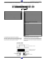
D
Abkürzungen /
+12A
+14/9V
+14A
+14M1
+14M2
+33V
+5A
+8M2
-28V
5V2D
AEH1/2
AFC
AFV
AGC
AL
AMLP
AMLR
APH
ARH
AUDINL
AUDINR
AUDOUTL
AUDOUTR
BGP
CAP
CLCKD1
CREV
CROT
CSI
CSYNC
CTL1/2
DATD1
DE
ENVC
ESPBH
FFP
FG
FMPV
FMR
FMRV
FTA
FV
GAER
GNDA
GNDD
GNDM1
GNDM2
HEHI
HELO
HP1
HSC
I/R
GB
Prescipciones para la soldadura de los circuitos
integrados MOS:
• Utilizar únicamente soldadores de baja tensión con transformadorseparador de la red.
• Tiempo máximo de soldadura: 5 segundos con una temperatura
entre 300 y 400 °C.
Abbreviation
+12V analog
+12V analog
14V oder 9V Versorgung
14V or 9V supply
für Capstan
capstan
+14V analog
+14V analog
+14V motor
+14V motor
+14V motor
+14V motor
+33V
+33V
+5,2V analog
+5.2V analog
+8V motor
+8V motor
-28V
-28V
+5,2V digital
+5.2V digital
Audio Löschkopf
audio erase head
Automatische
automatic frequency
Frequenzkontrolle
control
Audio von Empfangseinheit
audio from Frontend
Automatische Verstärkungsautomatic gain control
regelung
Standardton (Audio Linear)
Standard Sound (Audio Linear)
Audio Mono Linear Wiedergabe audio mono linearplayback
Audio Mono Linear Aufnahme audio mono linear record
Wiedergabekopf Audio
audio playback head
Aufnahmekopf Audio
audio record head
Audio Eingang links
audio in left
Audio Eingang rechts
audio in right
Audio Ausgang links
audio out left
Audio Ausgang rechts
audio out right
Burstauftastung
burst gate pulse
Capstan Geschwindigkeit
capstan speed
Clock IVC
clock IVC
Capstan "Reverse"
capstan reverse
Farbrotation
chroma rotation
Farb-Normkennung
colour standard inform.
Synchimpuls
composite sync
Kontrollimpulse
control pulse sig/ref
Daten IVC
data IVC
Ablaufsteuerung/DeckSequence Control/Deckelecelektronik
tronic
Hüllkurven Komperator
envelope comparator
Externe Wahl/Wiedergabe
ext. select/playback
V-Impuls / Testbild
feature frame pulse
Capstantacho
capstan tacho
FM Video-Wiedergabe
fm playback video
FM Aufnahmestrom
fm rec current
FM Videoaufnahme
fm record video signal
Fädeltacho
threading tacho
Empfangseinheit
Frontend
Löschoszillator Masse analog ground analog erease oscillator
Masse analog
ground analog
Masse digital
ground digital
Masse Motor 1
ground motor 1
Masse Motor 2
ground motor 2
Display-Heizung (HIGH)
display heater (HIGH)
Display-Heizung (LOW)
display heater (LOW)
Kopfimpuls 1 Video
head pulse 1 video
Kopfauswahl
head select control
Init und Aufnahmesperre
init/record protect
GRUNDIG Service-Technik
3. Los elementos MOS sólo deben cogerse por la cápsula, sin rozar
siquiera los terminales.
4. Pruebas y trabajos con los circuitos MOS sólo deben realizarse en
aparatos que estén puestos a tierra.
5. No extraer ni establecer contacto bajo tensión de funcionamiento de
los IC´s MOS enchufables.
6. En los componentes MOS canal-p no deben llegar tensiones
positivas (con respecto a la tensión de substrato VSS) a los
circuitos.
INIT
VBS
VFV
VMCO
VSB
VS
IO
W/R
WTL
Initialisierungsschalter
für das Laufwerk
Interrupt
Schaltspannung bei
Wiedergabe-Standardton
invertiert
invertierte Schalterspannung für EURO-AV-Buchse
Kontakt 8
Schaltspannung bei
Wiedergabe Video invertiert
Schaltspannung bei
Aufnahme invertiert
LED für Bandende/anfang
Kopfverstärker
Longplay
Netzanschluss
Hauptlöschkopf
Bedieneinheit
Chassisplatte
Modulator ein
Netzteil
Pal/Secam Schalter
"Mute" Audio
Spannung für Modulator
Spannung fixiert Modulator
Kopfscheibentacho
Reset bei Inbetriebnahme
Pulsbreiten modulierte
Abstimmspannung
Aufnahmeschutz
Kopfmotor ein
Aufnahme Video
Secam Band 1
I2C Bus - Takt
I2C Bus - Daten
CTL Sync zum Ablaufrechner
Bandende Erkennung
Bandanfang Erkennung
einfädeln / ausfädeln
Einfädelmotor
Einfädelmotor
Trackinginfo Video
Bild oder Zeilenimpuls
vom Csync
Video von IO zum VS
Video von Empfangseinheit
Video zum Modulator
Video von VS zum IO
Video/Chroma
In/Out
schreiben/lesen CTL-sync
Tacho Wickelteller links
inverse switching voltage for
playback video
inverse switching voltage for
record
LED tape start/(end
Head Amplifier
longplay
mains connection
main-erase-head
Keyboard Control Unit
Family Board
modulator on
Power Supply
pal/secam switch
mute audio
power analog modulator
power fixed modulator
head reel tacho
power on reset
pulse width mod.
tuning voltage
record protection
head-disk motor on
record video
secam band 1
I2C bus clock
I2C bus data
ctl-sync to sequence control
tape end detector
tape start detector
threading in/out
threading motor
threading motor
tracking information video
frame or line-pulse
from csync
video from IO to VS
video from Frontend
video modulator combiunit
video from VS to IO
Video/Chroma
In/Out
write/read CTL-sync
tacho generator, left spindle
WTR
Tacho Wickelteller rechts
tacho generator, right spindle
INT
IPAL
I8SC112
IPBV
IREC
LED
LHA
LP
MAINS1/2
MEH1/2
MDC…
MFB
MODON
MSM1
MSMS
MTA
PACO
PFCO
PG/FG
POR
PWM
RECP
REEL
REV
SB1
SCL
SDA
SYNC
TAE
TAS
THIO
TMO
TMO1/2
TRIV
V/H-SYNC
initialisation switch
for Deck Mechanism
interrupt
inverse switching voltage for
playback standard sound
inverse switching voltage for
EURO-AV-socket, contact 8
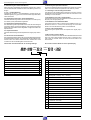
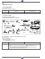
1 - 11
1. Operating Elements
Note:
This chapter contains excerpts from the
operating instructions. For further particulars
please refer to the corresponding operating
instructions (part number indicated in the
spare parts list).
Hinweis:
Dieses Kapitel enthält Auszüge aus der Bedienungsanleitung. Nähere Informationen entnehmen Sie bitte aus der entsprechenden
Bedienungsanleitung (Sachnummer siehe
Ersatzteilliste).
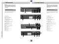
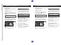
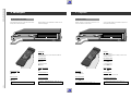
Die Videorecorder auf einen Blick
The Video Recorders at a Glance
Auf dieser Seite sind die Tasten und Anschlüsse der Videorecorder kurz erklärt. Die Bedienung entnehmen Sie bitte dem
jeweiligen Kapitel dieser Bedienungsanleitung.
1
2
3
4
5
1
On this page, the buttons and connections on the video
recorders are briefly explained. Please refer to the corresponding chapters of these operating instructions for a detailed
description.
2 3 4 56 7 89 ! " #
1
2
3
4
5
Cassettenfach
Cassettenauswurf
Beendet alle Funktionen (Stop)
Schaltet den Recorder ab (stand by)
Pause bei Aufnahme
Standbild bei Wiedergabe
6
Bildsuchlauf rückwärts (bei Wiedergabe)
Rücklauf (bei Stop)
7
8
Startet die Wiedergabe
9
!
"
#
$
%
&
(
)
~
+
,
Zur Programmplatzwahl (bei Stop)
(
Bildsuchlauf vorwärts (bei Wiedergabe)
Vorlauf (bei Stop)
)
1
~
+
2 6 9" 74
Aufnahme-Taste
Zur Programmplatzwahl (bei Stop)
Display
35
Zum Einstellen der Uhr und des Datums
Sendersuchlauf-Taste
Speicher-Taste
Netzanschluß
EURO-AV-Buchse (In / Out)
#
Antennenbuchsen
!8$ %&
Kanaleinsteller
Normumschalter
GRUNDIG Service-Technik
,
(
)
~
+
Cassette compartment
Cassette eject
Stops all functions (stop)
Switches the recorder to stand by
Pause on Record
freeze-frame on playback
6
Reverse picture search during playback
rewind (on stop)
7
8
Starts playback
9
!
"
#
$
%
&
(
)
~
+
,
For selecting programme positions (on stop)
Forward picture search (on playback)
fast forward (on stop)
Record button
For selecting programme positions (on stop)
Display
For setting the clock and date
Station finder
Memory button
Mains socket
EURO-AV socket (In / Out)
Aerial sockets
Channel selection
For changing the TV system
Allgemeiner Teil / General
1 - 12
1. Bedienelemente
GRUNDIG Service-Technik
1. Bedienelemente
1. Operating Elements
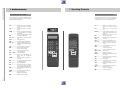
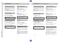
Die Fernbedienungen auf einen Blick
The Remote Control Handsets at a Glance
Auf dieser Seite sind die Tasten der Fernbedienung kurz
erklärt. Die Bedienung entnehmen Sie bitte dem jeweiligen
Kapitel dieser Bedienungsanleitung.
On this page, the buttons on the remote control handsets are
briefly explained. Please refer to the corresponding chapters
of these operating instructions for a detailed description.
8 ––––––––––––– Schaltet den Recorder ab (stand by);
“
8
“
–––––––––––– Switches the recorder to stand by;
activates and deactivates the child
lock.
aktiviert und deaktiviert die Kindersicherung.
“ –––––––––––– Aktiviert die Eingabe der CassettenCASS
Spielzeit.
“ –––––––––––– Activates
VCR 12
TIMER
:
START
DATE
DW
VPS
CASS
:
PROG
entry of cassette playing
time.
END
“ –––––––––– Eröffnet
“
T –––––––––––– Eröffnet die TIMER-Programmierung
und bestätigt TIMER-Daten.
“ ... “ ––––––– Ziffern-Tasten für verschiedene Eingaben.
“ ––––––––––– Taste ohne Funktion.
“ –––––––––––– Löscht einen belegten TIMER-Platz.
% ––––––– Wählt den Programmplatz (bei Stop);
& “
“
T –––––––––––– Starts the timer programming mode
and confirms timer data.
“ ... “ –––––– Numbered buttons for different entries.
“ ––––––––––– No function.
“ –––––––––––– Erases an occupied TIMER position.
& ––––––– Selects the station position (on stop);
% “
“
die TIMER-Programmierung
in die Fernbedienung und bestätigt
TIMER-Daten.
TIMER LCD
1
TIMER LCD
0
SELECT
CLEAR
Wählt Daten (bei der TIMER-Programmierung).
“ –––––––––––– Aktiviert die ATS euro plus-Funktion.
“ ––––––––––– Speichert Fernseh-Programme
(beim Programmeinstellen).
% –––––––––––– Zum Kontrollieren eines TIMER“
1
8
8
CASS
1
2
3
4
5
6
7
8
Platzes am Recorder.
M ; ––– Startet die Aufnahme.
“ –––––––––––– Schaltet auf Langspiel-Betrieb
RECORD
SP/LP
wieder zurück
Betrieb.
auf
und
Standardspiel-
“ ––––––––– Sucht den Beginn der aktuellen Aufzeichnung.
F –––––––––––– Bildsuchlauf rückwärts (bei Wiedergabe), Rücklauf (bei Stop).
J –––––––––––– Startet die Wiedergabe.
G –––––––––––– Bildsuchlauf vorwärts (bei Wiederga-
SELECT
0
ATS
STORE
J
RECORD
II
ii
TRACK.
PREV.
&
9
%
CLEAR
%
K
e
NEXT
TRACKING
3
4
5
6
7
8
9
SELECT
0
CLEAR
J RECORD K
%
II
e
ii
&
uu
ATS
“ –––––––––––– Activates the ATS euro plus function.
“ ––––––––––– Stores TV stations
(on station programming).
% –––––––––––– To check a TIMER on the recorder.
“
M ; ––– Starts recording.
“ ––––––––––– Standard play/Long play.
“ ––––––––– Searches for the beginning of the present recording.
F –––––––––––– Reverse picture search (on playback),
reverse wind (on stop).
J ––––––––––– Starts playback.
G –––––––––––– Forward picture search (on playback),
ATS
STORE
RECORD
NEXT
uu
STORE
selects data (on timer programming
mode).
TRACKING SP/LP
NEXT
RP 10
SP/LP
PREVIOUS
forward wind (on stop).
“ ––––––––––– Searches for the beginning of the next
recording.
“ ––––––––– Activates the Auto Tracking function.
K –––––––––––– Pause (on recording),
Freeze-frame (on playback).
` –––––––––––– Terminates all functions.
NEXT
TRACKING
1 - 13
Allgemeiner Teil / General
“ –––––––––––– Sucht den Beginn der nächsten Aufzeichnung.
“ ––––––––– Aktiviert die Auto Tracking-Funktion.
K –––––––––––– Pause (bei Aufnahme),
Standbild (bei Wiedergabe).
` –––––––––––– Beendet alle Funktionen (Stop).
2
PREVIOUS
RP 13
0
SELECT
CLEAR
1
SP/LP
PREVIOUS
be), Vorlauf (bei Stop); schaltet auf
Zeitlupe (während Wiedergabe-Pause).
TIMER
TIMER LCD
ATS
STORE
CASS
––––––––– Enables TIMER programming on the
remote control handset and confirms
TIMER data
Allgemeiner Teil / General
1 - 14
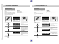
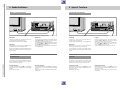
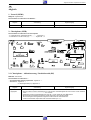
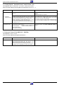
2. Anschließen und Einstellen
2. Connecting and Setting Up
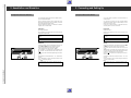
Fernsehgerät auf den Recorder abstimmen
Tuning the TV Receiver to the Recorder
Ihr Fernsehgerät empfängt auf bestimmten Kanälen die Programme verschiedener Sender.
Your TV set receives programmes from different stations on
certain channels.
Auch Ihr Recorder sendet auf einem solchen Kanal (UHFBereich, zwischen Kanal 30 und 40 ± 2 Kanäle), auf den Sie
jetzt Ihr Fernsehgerät einstellen müssen.
Damit Sie diesen Kanal finden ist im Recorder ein "Sender"
eingebaut, der ein Testbild sendet.
Your recorder also transmits on such a channel (between
channels 30 and 40 ± 2 channels in the UHF band), to which
the TV set must now be tuned.
So that you can find this channel, a "transmitter" that transmits a test pattern is built into the recorder.
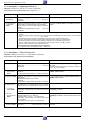
Vorbereiten
Preparation
Fernsehgerät einschalten.
Switch the TV set on.
Am Fernsehgerät den Programmplatz für den Videorecorder
wählen (AV-Programmplatz).
Select the AV programme position for the recorder on the
television set.
Antennenkabel aus der Buchse -II- des Recorders
ziehen.
Remove the aerial cable from the socket -II- of the
recorder.
Im Recorder darf sich keine Cassette befinden.
There should be no cassette in the recorder.
Abstimmen
>
Switch to the test pattern by simultaneously pressing the
and
buttons on the recorder while it is turned off.
Der Recorder "sendet" nach kurzer Zeit das Testbild.
In der Anzeige des Recorders erscheint: »T E S T«
Am Fernsehgerät – im UHF-Bereich, zwischen Kanal 30 und
40 + 2 Kanäle – das Testbild des Recorders suchen und speichern.
Wie das geht, steht in der Bedienungsanleitung des Fernsehgerätes.
The recorder "transmits" the test pattern after a short period
of time.
"TEST" appears in the display of the recorder. Search for the
recorder´s test pattern in the UHF band between the channels
30 and 40 + 2 channels and store it in the memory.
How this is done is explained in the operating instructions for
the TV receiver.
>
8
Tuning
Testbild einschalten, dazu bei abgeschaltetem Recorder die
Tasten
und
am Recorder gleichzeitig drücken.
J
J
8
Antennenkabel in die Antennenbuchse -II- des Recorders
stecken.
Insert the aerial cable plug into the aerial socket -II- of the
recorder.
Ist die Bildqualität in Ordnung, Einstellung beenden, dazu
Taste 8 am Recorder drücken.
If the picture quality is good, complete tuning by pressing the
8 button on the recorder.
Ist die Bildqualität nicht in Ordnung, gehen Sie nach dem
Kapitel auf der nächsten Seite vor.
If the picture quality is poor, proceed as described in the
chapter on the next page.
“
“
GRUNDIG Service-Technik
GRUNDIG Service-Technik
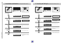
2. Anschließen und Einstellen Fernsehgerät auf den Recorder abstimmen
2. Connecting and Setting Up Tuning the TV Receiver to the Recorder
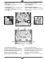
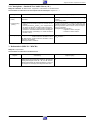
Bildqualität verbessern
Improving the picture quality
Wenn sich auf dem Bildschirm des Fernsehgerätes Schlangenlinien zeigen, ist der eingestellte Kanal mit einem FernsehProgramm belegt.
In diesem Fall gehen Sie wie folgt vor:
Taste 8 am Recorder drücken.
“
Am Fernsehgerät – im UHF-Bereich, zwischen Kanal 30 und
40 + 2 Kanäle – einen Kanal suchen, der nicht mit einem
Fernsehprogramm belegt ist (nur Rauschen am Bildschirm).
Kanal am Fernsehgerät speichern (siehe Bedienungsanleitung
des Fernsehgerätes).
Antennenkabel aus der Buchse -II- des Recorders ziehen.
>
Testbild einschalten, dazu die Tasten
und
Recorder gleichzeitig drücken.
Der Recorder sendet nach kurzer Zeit das Testbild.
Sender des Recorders abschalten und
einschalten
q
Switching the Recorder´s Transmitter Off and
On
In this case, carry out the following:
Wenn Ihnen viele Fernsehsender angeboten werden, die Ihr
Recorder im UHF-Bereich, zwischen Kanal 30 und 40 empfängt, kann es zu Bildstörungen im Recorder-Betrieb kommen. Deshalb können Sie den Sender des Recorders abschalten.
Damit das Bild-/Tonsignal des Recorders trotzdem zu
Ihrem Fernsehgerät gelangt, müssen die Geräte mit einem
EURO-AV-Kabel verbunden sein.
Press the 8 button on the recorder.
“
On the television, search for a channel in the UHF band between the channels 30 and 40 + 2 channels which is not
occupied by a station (only snow on the picture screen).
Store the channel found in the memory of the TV set (see
operating instructions for the TV set).
Remove the aerial cable from the socket -II- of the
recorder.
Im Recorder darf sich keine Cassette befinden.
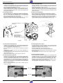
Sender des Recorders abschalten
>
`
Drücken Sie gleichzeitig die Tasten
und
am Recorder.
In der Anzeige des Recorders erscheint der aktuelle Zustand,
zum Beispiel: »O N «.
Drücken Sie gleichzeitig die Tasten
und
solange, bis
in der Anzeige am Recorder »O F F « erscheint.
> `
If your recorder receives many TV stations between the channels 30 and 40 in the UHF band, you may experience picture
interference when using your recorder. To avoid this, the
recorder´s transmitter can be switched off.
So that the picture/sound signal of the recorder can be
passed to the TV set, the two units must be connected by
means of a EURO-AV cable.
There should be no cassette in the recorder.
> J
Switch on the test pattern by pressing the
and
buttons on the recorder simultaneously.
The recorder transmits the test pattern after a short period of
time.
J am
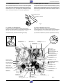
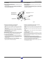
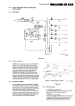
Drehen Sie den Kanaleinsteller (MOD./FREQ.) in der Rückseite des Recorders (siehe Abbildung) mit dem beigepacktem
Einstellstift etwas nach links oder rechts, bis das Testbild am
Bildschirm des Fernsehgerätes erscheint.
If wavy lines are visible on the TV picture, the channel tuned
to is already occupied by a TV station.
q
(MOD./FREQ.) on the back of
Turn the channel selector
the recorder (see illustration) with the alignment pin supplied
slightly to the right or left until the test pattern appears on the
screen.
Switching the recorder´s transmitter off
>
`
Press the
and
buttons on the recorder simultaneously.
The present mode appears in the recorder´s display, e.g.:
» ON «.
Press the
and
buttons simultaneously until » OFF «
appears in the recorder´s display.
>
`
The transmitter of the recorder is now switched off.
Der Sender des Recorders ist abgeschaltet.
Switching the recorder´s transmitter on
Sender des Recorders einschalten
x
MOD.
FREQ.
Antennenkabel wieder in die Buchse -II- des Recorders
stecken.
Einstellung mit Taste 8 am Recorder beenden.
“
>
`
>
`
Drücken Sie gleichzeitig die Tasten
und
am Recorder.
In der Anzeige des Recorders erscheint der aktuelle Zustand,
zum Beispiel: »O F F «.
Drücken Sie gleichzeitig die Tasten
und
am Recorder solange, bis in der Anzeige am Recorder »O N « erscheint.
Der Sender des Recorders ist eingeschaltet.
x
>
`
>
`
Press the
and
buttons on the recorder simultaneously.
The present mode appears in the recorder´s display, e.g.:
» OFF «.
Press the
and
buttons on the recorder simultaneously until »O N « appears in the recorder´s display.
MOD.
FREQ.
Reinsert the aerial cable into the socket -II- of the recorder.
The transmitter of the recorders is now switched on.
Complete the adjustment by pressing the 8 button on the
recorder.
“
Allgemeiner Teil / General
1 - 15
Allgemeiner Teil / General
1 - 16
2. Anschließen und Einstellen
2. Connecting and Setting Up
Uhrzeit und Datum einstellen
Setting Time and Date
Die Daten für Uhrzeit und Datum gehen verloren, wenn
der Recorder ca. 7 Stunden vom Stromnetz getrennt ist.
Time and date data are lost when the recorder is disconnected from the mains for approx. 7 hours.
8
8
8
Drücken Sie diese Tasten am
Recorder
1. Funktion anwählen
> J
J
und
2. Uhrzeit einstellen
W Q
J
oder
3. Jahr einstellen
W Q
J
oder
4. Monat einstellen
W Q
J
oder
GRUNDIG Service-Technik
5. Tag einstellen
W Q
J
oder
8
In der Anzeige am Recorder
sehen Sie
Erläuterungen
TE:ST
PROG
DATE
88
START
STOP,
88:88
T I:ME
PROG
DATE
88
START
STOP,
I5:00
T I:ME
PROG
DATE
88
START
STOP,
20:00
YE:AR
PROG
DATE
88
START
STOP,
I9:93
YE:AR
PROG
DATE
88
START
STOP,
I9:93
MO:N8
PROG
DATE
START
STOP,
I9:0 I
MO:N8
PROG
DATE
START
STOP,
I9:03
DA: TE
PROG
DATE
START
STOP,
I9:0 I
DA: TE
PROG
DATE
START
STOP,
I9: I7
OK:AR
PROG
DATE
88
START
STOP,
20:I5
Press these buttons on the recorder
1. Selecting function
Tasten gleichzeitig drücken.
Werden Daten vom Recorder nicht
angenommen (zum Beispiel 35. =
falsches Datum), erscheint in der
Anzeige des Recorders »– –«, wiederholen Sie die Eingabe
Uhrzeit und Datum können Sie auch
mit den Ziffern-Tasten 1 ... 0
der Fernbedienung eingeben.
Uhrzeit und Jahr geben Sie vierstellig ein, Monat und Tag zweistellig.
“ “
> J
J
and
2. Entering time
W Q
J
or
3. Entering year
W Q
J
or
4. Entering month
W Q
J
or
Nach dem Drücken der Taste
tet die Uhr.
J star-
5. Entering day
W Q
J
or
You will see this on the display of
the recorder
Explanations
TE:ST
PROG
DATE
88
START
STOP,
88:88
T I:ME
PROG
DATE
88
START
STOP,
I5:00
If data items are not accepted by the
recorder (e.g. 35. = incorrect date),
» – –« appears in the recorder´s display; re-enter input.
T I:ME
PROG
DATE
88
START
STOP,
20:00
YE:AR
PROG
DATE
88
START
STOP,
I9:93
You can enter time and date with
the numbered buttons 1 ... 0
on the remote control.
Enter time and year as a 4 digit
number, month and day as 2 digits.
YE:AR
PROG
DATE
88
START
STOP,
I9:93
MO:N8
PROG
DATE
START
STOP,
I9:0 I
MO:N8
PROG
DATE
START
STOP,
I9:03
DA: TE
PROG
DATE
START
STOP,
I9:0 I
DA: TE
PROG
DATE
START
STOP,
I9: I7
OK:AR
PROG
DATE
88
START
STOP,
20:I5
Press buttons simultaneously.
“ “
The clock starts after pressing the
button.
J
GRUNDIG Service-Technik
2. Anschließen und Einstellen
2. Connecting and Setting Up
Fernseh-Programme einstellen, mit dem
Suchlauf-Speicher-System (ATS euro plus)
Tuning to TV Stations with the Automatic Tuning
System (ATS euro plus)
Vorbereiten
Preparation
Fernsehgerät einschalten.
Switch the TV set on.
Am Fernsehgerät den Programmplatz für den Videorecorder
wählen (AV-Programmplatz).
Sie können das Einstellen am Bildschirm kontrollieren.
Select the AV programme position for the recorder on the TV
set.
You can now check the settings on the TV screen.
8
8
1
CAS
2
4
3
5
7
6
8
SELE
CT
J
9
0
CLEA
REC
ORD
ii
K
R
e
PREV
IOUS
S
1
TIME
R
ATS
SP/L
RP
0
CLEA
R
K
e
PREV
IOUS
TIME
R
&
%
II
uu
STO
RE
ATS
T
S
6
9
CT
REC
ORD
II
NEX
TRAC
KING
CAS
3
5
8
SELE
J
ii
uu
STO
RE
2
4
7
&
%
NEX
T
TRAC
KING
SP/L
P
P
RP
10
10
8
Drücken Sie diese Tasten der
Fernbedienung
8
In der Anzeige am Recorder
sehen Sie
1. ATS euro plus-Funktion anwählen
`
“
ATS ,
Alle vorher gespeicherten Kanalzahlen werden gelöscht.
AT:S +
PROG
DATE
88
START
STOP,
88:88
Der ATS euro plus Suchlauf wird
gestartet, das rollierende Symbol » 0 «
zeigt die Suche an.
OK:88
PROG
DATE
88
START
STOP,
88:88
Der Recorder sucht alle Kanalzahlen
nach Fernseh-Programmen ab, sortiert
und speichert sie.
PROG
0I
,
88:88
CA:SS
2. Fernseh-Programme überprüfen
a) Programmplätze anwählen
% “
&
“
oder
,
Erläuterungen
PROG
88:88 02
,
CA:SS
`
“
ATS ,
All previously stored channel numbers will be erased.
AT:S +
PROG
DATE
88
START
STOP,
88:88
The ATS euro plus tuning function
starts; the scrolling symbol » 0 « indicates that the recorder is searching.
OK:88
PROG
DATE
88
START
STOP,
88:88
The recorder searches for all channels
on which TV stations are broadcasting,
sorts, and stores them.
PROG
0I
,
CA:SS
After a short period of time, the recorder has completed the ATS euro
plus tuning function.
88:88
In der Anzeige am Recorder erscheint
»O K «.
Explanations
» O K « appears in the display.
Überprüfen Sie jetzt, ob Ihnen die
Zuordnung der Fernseh-Programme
zusagt.
2. Checking the TV stations
Möchten Sie die Zuordnung ändern,
setzen Sie die Bedienung bei Pkt. 3 fort.
% “
&
“
Now check to see if you are satisfied
with the order in which the TV stations
are allocated.
a) Select a programme position
or
,
PROG
88:88 02
,
CA:SS
If you wish to change the allocation,
proceed to point 3.
b) Terminate the adjustment
I5:00
Die aktuelle Uhrzeit, im Beispiel 15:00
Uhr, wird angezeigt.
8
“
,
I5:00
The current time is displayed, 15:00
hours in the example.
1 - 17
Allgemeiner Teil / General
,
You will see this on the display of
the recorder
1. Selecting ATS euro plus function
Nach einiger Zeit hat der Recorder den
ATS euro plus Suchlauf durchgeführt.
b) Einstellung beenden
8
“
Press these buttons on the remote
control
Drücken Sie diese Tasten der
Fernbedienung
In der Anzeige am Recorder
sehen Sie
Erläuterungen
3. Fernseh-Programme umsortieren
oder
,
PROG
05
,
CA:SS
Taste so oft drücken, bis am Bildschirm
Ihres Fernsehgerätes das Fernseh-Programm erscheint, das Sie auf einen
anderen Programmplatz "legen" möchten. In der Anzeige am Recorder
erscheint die Nummer des Programmplatzes, zum Beispiel: »05 «.
b) Programmplatz markieren
“
STORE ,
PROG
STORE ,
e) Einstellung beenden
“
8
,
a) Select a programme position
`
% “
&
“
or
,
“
8P:05
05
CA:SS
PROG
05
PROG
05
8P:05
05
8P:
,
STORE ,
c) select a new programme position
PROG
8P:
05
I2
d) Fernseh-Programm speichern
“
You will see this on the display of the
recorder
Explanations
Press the button until the TV station
you wish to "move" to another programme position appears on your TV
screen. The number of the programme
position will appear in the display of the
recorder, e.g.: » 05 «.
b) mark the programme position
c) Neuen Programmplatz anwählen
% oder “
&,
“
Press these buttons on the
remote control
3. Resorting TV stations
a) Programmplatz anwählen
`
% “
&
“
2. Connecting and Setting Up Tuning the Recorder to TV Stations
PROG
I2
,
CA:SS
Taste so oft drücken, bis die Nummer
des "neuen" Programmplatzes in der
Anzeige des Recorders erscheint, zum
Beispiel: »P I 2 «.
Das Fernseh-Programm ist auf dem
neuen Programmplatz gespeichert, die
anderen Fernseh-Programme verschieben sich um eine Position.
Wollen Sie weitere Fernseh-Programme
umsortieren, so wiederholen Sie den
Vorgang ab Pkt. 3 a.
% “
&
“
or
,
PROG
I2
d) store the TV station
“
STORE ,
e) terminate the adjustments
8
“
,
PROG
I2
,
CA:SS
Press the button until the number of the
"new" programme position appears in
the display of the recorders, e.g.: »P I2 «.
The TV station is stored in the new programme position, and the other TV stations are shifted over one position.
If you wish to re-sort further TV stations, repeat the procedure starting
with point 3 a.
Allgemeiner Teil / General
1 - 18
2. Anschließen und Einstellen Fernseh-Programme einstellen
GRUNDIG Service-Technik
GRUNDIG Service-Technik
2. Anschließen und Einstellen
2. Connecting and Setting Up
Fernseh-Programme einstellen,
von Hand
Tuning to TV Stations,
manually
Vorbereiten
Zusätzlich zum Suchlauf-Speicher-System bietet der Recorder zwei weitere Möglichkeiten zum Einstellen der FernsehProgramme.
Am Fernsehgerät den Programmplatz für den Videorecorder
wählen (AV-Programmplatz).
Sie können das Einstellen am Bildschirm kontrollieren.
Die Variante 1 können Sie benützen, wenn an Ihrem Empfangsort ein neues Fernseh-Programm hinzu kommt.
Preparation
In addition to the ATS function, your recorder offers you two
additional methods of tuning to TV stations.
Fernsehgerät einschalten.
Die Variante 2 verwenden Sie, wenn das Suchlauf-SpeicherSystem ein Fernseh-Programm nicht speichern konnte, weil
zum Beispiel die Empfangsqualität zu schwach ist.
Switch the TV set on.
Variant 1 can be used when a new TV station can be received
in your area.
Select the AV programme position for the recorder on the TV
set.
You can now check the settings on the TV screen.
Use variant 2 when the ATS function cannot store a TV station if, for example, the reception quality is too poor.
Variant 1
Variante 1
8
8
1
CAS
2
4
3
5
7
6
8
SELE
CT
J
9
0
CLEA
REC
ORD
ii
K
e
PREV
IOUS
R
S
1
TIME
R
NEX
TRAC
KING
SP/L
RP
0
ii
CLEA
R
K
e
PREV
IOUS
uu
ATS
6
9
CT
REC
ORD
TIME
R
&
%
II
uu
STO
RE
ATS
T
S
3
5
8
SELE
J
II
STO
RE
CAS
2
4
7
&
%
NEX
T
TRAC
KING
SP/L
P
P
RP
10
10
8
Drücken Sie diese Tasten der
Fernbedienung
8
In der Anzeige am Recorder
sehen Sie
Erläuterungen
1. Freien Programmplatz wählen
`
“ ... “
1
0
PROG
,
2. Fernseh-Programm suchen
“
STORE ,
SK: IP
PROG
8I
2I
CA:SS
CA:SS
Die Anzeige »S K I P « zeigt den freien Programmplatz an.
Programmplatz ein- oder zweistellig
anwählen, im Beispiel Programmplatz 21.
You will see this on the display of
the recorder
`
“ ... “
0
,
SK: IP
PROG
8I
CA:SS
PROG
2I
CA:SS
“
STORE ,
“
STORE ,
8
“
,
2I
CA:SS
Zum Suchen eines weiteren "neuen" Fernseh-Programmes wiederholen Sie die
Einstellung ab Pkt.1.
Findet der Recorder kein neues FernsehProgramm, beendet er automatisch die
Einstellung.
TU:NE
3. Storing the TV station
“
STORE ,
4. Terminating the adjustments
8
“
,
Select a one or two digit programme
position, 21 in the example.
PROG
2I
CA:SS
To search for additional "new" TV stations,
repeat the procedure starting with point 1.
If the recorder cannot find a new TV station, it automatically terminates the
adjustment.
1 - 19
Allgemeiner Teil / General
4. Einstellung beenden
PROG
The » SKIP « display indicates the free
programme position.
If the "new" TV station is found, it appears
on the screen; the number of the programme position blinks in the display on
the recorder.
If this is not the desired TV station, restart
the search function by pressing the ATS
button.
2. Searching for a TV station
“
3. Fernseh-Programm speichern
Explanations
1. Selecting a free programme
position
1
Wurde das "neue" Fernseh-Programm
gefunden, erscheint das Bild des FernsehProgrammes am Bildschirm, in der
Anzeige am Recorder blinkt die Nummer
des Programmplatzes.
Ist es nicht das gewünschte Fernseh-Programm, starten Sie den Suchlauf erneut,
dazu Taste ATS drücken.
TU:NE
Press these buttons on the remote
control
2. Connecting and Setting Up Tuning the Recorder to TV Stations, Variant 2
Variante 2
Variant 2
8
8
1
CAS
2
4
3
5
7
6
8
SELE
CT
J
9
0
CLEA
REC
ORD
ii
K
e
PREV
IOUS
R
S
1
TIME
R
ATS
SP/L
RP
0
CLEA
R
K
e
PREV
IOUS
TIME
R
&
%
II
uu
STO
RE
ATS
T
S
6
9
CT
REC
ORD
II
NEX
TRAC
KING
CAS
3
5
8
SELE
J
ii
uu
STO
RE
2
4
7
&
%
NEX
T
TRAC
KING
SP/L
P
P
RP
10
10
8
Drücken Sie diese Tasten der
Fernbedienung
8
In der Anzeige am Recorder
sehen Sie
Erläuterungen
1. Funktion anwählen
Press these buttons on the remote
control
You will see this on the display of
the recorder
Explanations
1. Selecting function
8
“
“
,
8
“
“
,
MA:N8
STORE ,
0
Taste
“ länger als 5 Sekunden
STORE
2. Fernseh-Programm suchen
% oder “
&,
“
MA:N8
STORE ,
0
Press the
“ button for more than
STORE
2. Searching for a TV station
MA:N8
% “
&
“
0
or
,
Das rollierende Symbol »0 « zeigt die
Suche an.
MA:N8
0
The scrolling symbol » 0 « indicates that
the recorder is searching.
3. Storing a TV station
“
STORE ,
3. Fernseh-Programm speichern
“
ME:MO
STORE ,
8P:0 I
ME:MO
8P:0 I
ME:MO
8P:20
Select a free programme position.
Wählen Sie einen freien Programmplatz.
4. Selecting a programme position
% “
&
“
or
,
4. Programmplatz wählen
% “
&
“
oder
,
ME:MO
8P:20
Programme position » P 20 « is selected in the example.
Im Beispiel Programmplatz »P 20 «.
5. Storing the programme position
GRUNDIG Service-Technik
“
STORE ,
5. Programmplatz speichern
“
STORE ,
I9: 30
Zum Suchen weiterer Fernseh-Programme wiederholen Sie die Einstellung ab Pkt. 1.
I9: 30
To search for additional TV stations,
repeat the procedure starting with point
1.
Allgemeiner Teil / General
1 - 20
2. Anschließen und Einstellen Fernseh-Programme einstellen, Variante 2
GRUNDIG Service-Technik
3. Wiedergabe
3. Playback
Die Wiedergabe auf einen Blick
Playback at a Glance
Diese Funktionen können Sie mit den Tasten an der Fernbedienung oder am Recorder ausführen.
Bespielte Cassette in das Cassettenfach schieben. Sie wird
automatisch eingezogen.
Playback operation is possible with the buttons on the remote control handset or on the recorder.
Insert a recorded cassette into the cassette compartment. It
will be pulled in automatically.
8
8
8
8
1
SELE
J
REC
ORD
ii
PREV
6
8
CT
9
0
CLE
AR
K
e
IOUS
TIM
ER
3
5
7
1
CA
SS
2
4
&
%
II
uu
STO
RE
ATS
TRA
Wiedergabe
J drücken.
J
ORD
Ist das Bandende erreicht, spult der Recorder das Band an
den Anfang zurück.
ii
ING
RP
SP/L
P
10
6
8
9
0
CLE
AR
K
e
PREV
IOUS
%
II
uu
STO
RE
ATS
NEX
T
CK
REC
SS
NEX
TRA
CK
ING
RP
1
0
in Funktion Stop
drücken.
G
Weitere Umspulfunktionen finden Sie auf Seite 1 - 22.
Pause/freeze-frame
To stop playback,
Press the
button.
Wiedergabe fortsetzen,
drücken.
J
To continue playback,
Press the
button.
Wiedergabe beenden
Ending playback
K
J
Press the
` button.
Fast rewind
With stop selected,
press the
button.
Cassette entnehmen
F
> am Recorder drücken.
Fast forward wind
Recorder abschalten
With stop selected,
press the
button.
8 drücken.
“
Ausführliche
Seite 1 - 22.
G
Wiedergabefunktionen
finden
Sie
auf
For further tape wind functions, see page 1 - 22.
Cassette ejection
Press the
> button on the recorder.
Switching the recorder off
Press 8 .
“
For detailed playback functions, refer to page 1 - 22.
1 - 21
Allgemeiner Teil / General
Band vorspulen
J
Press the
button.
If the recorder reaches the end of the tape, it rewinds to the
beginning of the tape.
K
Band zurückspulen
F
Playback
Wiedergabe anhalten,
drücken.
` drücken.
in Funktion Stop
drücken.
ER
&
T
SP/L
P
Pause/Standbild
TIM
3
5
7
SELE
CT
CA
2
4
Bildqualität optimieren (Auto Tracking)
Nach dem Einschieben der Cassette und dem Starten der
Wiedergabe stimmt der Recorder automatisch auf beste Bildqualität ab (Auto Tracking).
Die Auto Tracking-Funktion kann wieder aktiviert werden,
dazu Taste TRACKING während der Wiedergabe drücken.
Während der Abstimmung erscheint am Recorder die Anzeige:
»A U T O « und die Bild-/Tonqualität kann sich verändern.
“
Vorwärts
(9-/3-fache Wiedergabegeschwindigkeit)
Während der Wiedergabe Taste
ein-, oder zweimal
drücken – Bildsuchlauf vorwärts.
Am Recorder erscheint die Anzeige: »S C A N uu « oder
»F A S T uu «.
G
Auf Wiedergabe schalten, dazu Taste
J drücken.
Optimizing the Picture Quality (Auto Tracking)
After having inserted a cassette and started playback, the
recorder adjusts automatically for the best possible picture
quality (Auto Tracking).
The Auto Tracking function can be reactivated by pressing the
TRACKING button during playback.
During this adjustment, the indication » AUTO « appears on
the recorder´s display and the picture/sound quality may
change.
“
Am Recorder erscheint die Anzeige: »P S E « und »II«.
J drücken.
Picture Serach, Forward/Reverse*
Forward
(9-/3-times the normal playback speed)
During playback, press the
button once or twice – this
activates forward picture search.
The display »S C A N uu « or »F A S T uu « appears on the
recorder.
G
Press the
J button to return to playback.
Reverse
(9-fache Wiedergabegeschwindigkeit)
Während der Wiedergabe Taste
einmal drücken
– Bildsuchlauf rückwärts.
Am Recorder erscheint die Anzeige: »S C A N ii «.
Playback-Pause/Freeze-Frame
F
K drücken.
Auf Wiedergabe schalten, dazu Taste
Bildsuchlauf, vorwärts/rückwärts*
Rückwärts
Wiedergabe-Pause/Standbild
Während der Wiedergabe Taste
3. Playback General, Fast Tape Wind and Search Functions
Auf Wiedergabe schalten, dazu Taste
J drücken.
F
Press the
Die Dauer des Bildsuchlaufes ist zeitlich begrenzt. Danach
schaltet der Recorder auf Wiedergabe.
Standbilder schrittweise vorwärts fortschalten*
Band umspulen
K
button during playback.
The recorder displays: »P S E « and »II«.
Press the
Die Standbilddauer ist zeitlich begrenzt. Danach schaltet
der Recorder auf Wiedergabe.
(9 times the normal playback speed).
During playback, press the
button once – this activates
reverse picture search.
The display »S C A N ii « appears on the recorder.
Press the
J button to return to playback.
J button to return to normal playback.
The freeze-frame function is limited to a certain time. After
this time, the recorder will switch to playback.
The picture search function is limited to a certain time.
After this time, the recorder will switch to playback.
Fast Tape Wind
Freeze-Frame Stepping*
Während der Wiedergabe Taste
Taste
K drücken.
Am Recorder erscheint die Anzeige: »P S E « und »II«.
Auf das nächste Standbild schalten, dazu Taste
K drücken.
Mehrfaches Drücken schaltet das Standbild schrittweise weiter.
Auf Wiedergabe schalten, dazu Taste
` drücken.
Press the
G drücken.
Schnell zurückspulen, dazu Taste F drücken.
During playback, press the
Am Bandanfang bzw. -ende schaltet der Recorder auf Stop.
Press the
Schnell vorspulen, dazu Taste
Umspulen mit Taste
` beenden.
J drücken.
The recorder displays »P S E « and »II«.
“
Denn Beginn der nächsten oder der aktuellen
Aufzeichnung finden
K button to step to the next freeze-frame.
Repeatedly pressing the button selects the freeze-frames step
by step.
Press the
Wenn bei der Wiedergabefunktion Standbild das Bild zittert oder unruhig wirkt, kann es optimiert werden. Dazu
Taste TRACKING so oft drücken, bis das Bild ruhig wirkt.
K button.
If the picture trembles or appears unsteady during the
playback function of freeze-frame, you can optimize the
picture quality by pressing the TRACKING button until the picture appears steady.
G button.
F button.
At the beginning or the end of the tape, the recorder switches
to stop.
Terminate tape winding with the
` button.
Locating the Beginning of the Next or Present
Recording
This function allows you to locate the beginning of any of
your own recordings quickly and accurately.
For this, electronic "marks" (VISS marks = Video Index
Search System) are automatically placed at the beginning of
each of your own recordings.
“
GRUNDIG Service-Technik
Taste NEXT drücken, am Recorder erscheint die Anzeige:
»N E XT «. Das Band wird automatisch an den Anfang der
nächsten Aufzeichnung gespult, dort beginnt die Wiedergabe.
“
Press the NEXT button; on the recorder, the indication
»NEXT « appears. The tape is automatically wound to the
beginning of the next recording and playback is started there.
“
Taste PREVIOUS drücken, am Recorder erscheint die Anzeige:
»P R E V. «. Das Band wird automatisch an den Anfang der
aktuellen Aufzeichnung gespult, dort beginnt die Wiedergabe.
*mit Störstreifen
For fast rewind: press the
J button to return to normal to playback.
“
Damit finden Sie präzise und schnell den Beginn jeder Eigenaufnahme.
Dazu werden auf das Band – bei Beginn jeder Eigenaufnahme
– automatisch "Marken" (VISS-Marken = Video Index Search
System) gesetzt.
` button.
For fast forward wind: press the
“
Press the PREVIOUS button; on the recorder, the indication
»PREV. « appears. The tape is automatically wound to the
beginning of the present recording and playback is started
there.
*With interference bars
Allgemeiner Teil / General
1 - 22
3. Wiedergabe allgemein, Umspul- und Suchfunktionen
GRUNDIG Service-Technik
4. Aufnahme sofort
4. Immediate Recording
Die Aufnahme auf einen Blick
Recording at a Glance
Diese Funktionen können Sie mit den Tasten an der Fernbedienung oder am Recorder ausführen.
Cassette mit ausreichender Spieldauer in das Cassettenfach
schieben, Löschsicherung beachten.
You can make recordings either with the help of the remote
control or with the buttons on the recorder.
Insert a cassette with sufficient playing time and which is not
protected against recording into the cassette compartment.
8
8
Programmplatz wählen – schrittweise
Selecting a programme position - step by step
% oder “
& an der Fernbedienung drücken, oder
“
S oder A am Recorder drücken.
Nicht belegte Programmplätze können nicht angewählt
werden.
8
1
SELE
J
CT
REC
ORD
ii
PREV
6
9
0
CLE
AR
K
e
IOUS
1
TIM
ER
3
5
8
&
%
II
uu
STO
RE
ATS
TRA
NEX
T
CK
ING
RP
Aufnahme starten
J
M ; an der Fernbedienung gleichzeitig drücken,
oder
X am Recorder drücken.
ii
6
9
0
CLE
AR
K
e
PREV
IOUS
TIM
ER
&
%
II
uu
STO
RE
ATS
NEX
TRA
CK
SP/L
P
10
REC
ORD
RECORD
SS
3
5
8
SELE
CT
CA
2
4
7
ING
T
Starting recording
M
RECORD
Simultaneously press
or
press
on the recorder.
X
SP/L
Aufnahme unterbrechen/Pause
0
Interrupting recording/pause
Press the
drücken.
K button.
To continue recording
Aufnahme fortsetzen
M
RECORD
Simultaneously press
or
press
on the recorder.
M ; an der Fernbedienung gleichzeitig drücken
oder
X am Recorder drücken.
RECORD
Terminating recording
` drücken.
With stop selected
press the
button.
Press the
Cassette entnehmen
Fast forward wind
> am Recorder drücken.
With stop selected,
press the
button.
in Funktion Stop
drücken.
F
` button.
Removing the cassette
G
in Funktion Stop
drücken.
G
Recorder abschalten
Ausführliche Aufnahmefunktionen finden Sie auf Seite 1 - 24.
8 drücken.
“
For a detailed description of the recording functions, refer
to page 1 - 24.
Press
> on the recorder.
Switching the recorder off
Press the 8
“ button.
1 - 23
Allgemeiner Teil / General
Aufnahme beenden
; on the remote control,
X
Fast rewind
Band zurückspulen
Band vorspulen
; on the remote control,
P
RP
1
K
F
% or “
& button on the remote control, or
“
S or A button on the recorder.
Programme positions which are not occupied by a station
cannot be selected.
8
CA
SS
2
4
7
Press the
press the
5. Immediate Recording
Vorbereiten
Stoppzeit ändern
Preparation
Changing the Stop Time
Fernsehgerät einschalten.
Wollen Sie die Stoppzeit während der Aufnahme ändern,
drücken Sie die Taste CLEAR und danach beide Tasten
RECORD
der Fernbedienung oder Taste
am
Recorder so oft, bis die gewünschte Stoppzeit erreicht ist.
Switch the TV set on.
If you wish to change the stop time while recording, press the
CLEAR button and then both of the
RECORD
buttons on
the remote control, or repeatedly press the
button on
the recorder until the desired stop time is displayed.
Am Fernsehgerät den Programmplatz für den Videorecorder
wählen (AV-Programmplatz), dient als Kontrollmonitor.
“
M
;
X
Cassette mit ausreichender Spieldauer einschieben, Löschsicherung beachten.
Select the AV programme position for the recorder on the TV
set. This serves as a monitor for checking.
Aufnahme unterbrechen (Pause)
Während der Aufnahme Taste
“ “
Wurde ein Programmplatz gewählt, auf dem kein FernsehProgramm gespeichert ist, erscheint in der Anzeige am
Recorder: »5 K I P «.
Aufnahme starten
Interrupting Recording (Pause)
Press the
M
;
RECORD
Aufnahme mit den Tasten
der Fernbedienung
oder Taste
am Recorder fortsetzen.
Die Funktion Aufnahme-Pause ist zeitlich begrenzt, danach
schaltet der Recorder auf Stop.
X
0I
START
S TOP
80 .0 I
Select the desired TV programme on the programme positions 1 to 9 with the numbered buttons 1 ... 9 ,
or
for TV stations in the programme positions 10 to 42, first
enter the tens position and then, within 2 seconds, the units
position.
“ “
If you have selected a programme position which is not occupied by a station, »5KIP « appears in the display of the recorder.
Aufnahme sofort beenden
Starting Recording
` beenden.
;
X
PROG 0 I
0.0I
REC und e
K drücken.
Am Recorder erscheint zusätzlich die Anzeige: »PSE « und
»II«.
Aufnahme mit Taste
RECORD
Beide Tasten
der Fernbedienung drücken,
oder
Taste
am Recorder drücken. Die Aufnahme beginnt, in
der Anzeige am Recorder erscheint zum Beispiel:
PROG
DATE
Aufzeichnungen nahtlos aneinander reihen
(Assemble-Schnitt)
M
X
e
= Programmplatz 1 gewählt
= abgelaufene Spielzeit
= Aufnahme-Anzeige
Suchen Sie während der Wiedergabe die Bandstelle, an der
die neue Aufnahme angesetzt werden soll, danach drücken
Sie Taste
.
K
Recorder auf Aufnahme-Pause schalten, dazu beide Tasten
M ; der Fernbedienung drücken,
oder Taste X am Recorder drücken, gewünschtes Programm mit den Ziffern-Tasten “ ... “ ein- oder zweistellig eingeben.
“Neue” Aufnahme starten, dazu Taste M
; der
Fernbedienung oder Taste X am Recorder drücken.
RECORD
1
ME:MO
PROG 0 I
0.0I
REC and e
PROG
DATE
0I
START
S TOP
80 .0 I
REC
e
= programme position 1 selected.
= elapsed playing time.
= indicates recording.
0
RECORD
If the cassette is protected against accidental erasure,
»PROT « (protected) appears in the display of the recorder
and the cassette is ejected.
Stoppzeit in 30 Minuten-Schritten eingeben
GRUNDIG Service-Technik
X
RECORD
Tasten
der Fernbedienung oder Taste
am
Recorder während der Aufnahme drücken, in der Anzeige am
Recorder erscheint: »STOP « und die aktuelle Uhrzeit plus
30 Minuten.
Gewünschte Stoppzeit durch wiederholtes Drücken der
RECORD
der Fernbedienung oder Taste
am
Tasten
Recorder in 30-Minuten-Schritten eingeben.
;
;
X
Terminating Recording Immediately
` button to terminate recording.
;
RECORD
Press the two
buttons on the remote control,
or
press the
button on the recorder. Recording is started
and an indication appears in the display of the recorder, for
example:
Entering a Stop Time
M
M
RECORD
Continue recording by pressing the two
buttons on the remote control or the
button on the recorder.
The recording-pause function is limited to a certain time.
After this time, the recorder will switch to stop.
Press the
Bei der Wiedergabe sehen Sie nahtlose Übergänge ohne
Störzonen. Man nennt dies Assemble-Schnitt (assemble =
anfügen).
Stoppzeit eingeben
;
K button during recording.
The indications »II« and »PSE « also appear in the display of
the recorder.
Assembling Recordings with Clean Joints
(Assembly Editing)
REC
Ist die Cassette gegen Neubespielen geschützt, erscheint
in der Anzeige am Recorder: »P R OT « (Protected =
geschützt) und die Cassette wird ausgeschoben.
M
;
X
Selecting a Programme Position - Directly
Gewünschtes Fernseh-Programm der Programmplätze 1 bis
9 mit den Ziffern-Tasten 1 ... 9 anwählen,
oder
für Fernseh-Programme der Programmplätze 10 bis 42 die
10er-Stelle eingeben und innerhalb 2 Sekunden die 1er-Stelle
eingeben.
ME:MO
M
Insert a cassette with sufficient playing time which is not protected against recording.
Programmplatz wählen – direkt
M
“
X
Entering the stop time in 30-minute steps
M
;
RECORD
Press the
buttons on the remote control or
button on the recorder while recording; »STOP «
the
appears in the display of the recorder as well as the current
time plus 30 minutes.
X
Enter the desired stop time in 30-minute steps by repeatedly
RECORD
pressing the
buttons on the remote control or
the
button on the recorder.
M
X
;
During playback, locate the tape position where you wish to
join the new recording, then press the
button.
K
Switch the recorder to recording-pause by pressing the two
RECORD
buttons together on the remote control,
or by pressing the
button on the recorder, and enter the
desired programme as one or two figures with the numbered
buttons 1 ... 0 .
RECORD
Start the “new” recording by pressing the two
buttons together on the remote control or the
button on
the recorder.
When you play the assembled recordings back, you will see
smooth joints without any flaws. This is called assembly editing.
M
;
X
“ “
M
X
;
Allgemeiner Teil / General
1 - 24
5. Aufnahme sofort
GRUNDIG Service-Technik
5. Aufnahme programmieren
5. Record Programming
Programmieren mit der Fernbedienung
und der Anzeige des Recorders
Programming with the Remote Control
and the Display on the Recorder
Vorbereiten
Der Recorder kann so programmiert werden, daß er zu einer
späteren Zeit aufzeichnet.
Sie können sechs Sendungen innerhalb von 31 Tagen vorprogrammieren.
Die Daten können Sie mit den Ziffern-Tasten
mit den Tasten
/
eingeben.
& “
%
“
Cassette mit ausreichender Spieldauer einschieben, Löschsicherung beachten.
You can enter the data with the numbered buttons
or with the
/
buttons.
& “
%
“
“ ... “ oder
1
0
Preparation
The recorder can be programmed to record at a later date.
You can pre-programme 6 programmes within a period of 31
days.
Insert a cassette with sufficient playing time which is not protected against new recording.
“ ... “
1
0
The following example shows how to enter using the
/
buttons.
& “
%
“
Im folgenden Beispiel ist die Eingabe mit den Tasten
/
beschrieben.
& “
%
“
Programming example
Programmierbeispiel
8
1
CAS
J
3
6
8
9
0
CLEA
REC
ORD
ii
K
e
PREV
IOUS
6
9
CT
5
7
SELE
CT
3
5
8
SELE
CAS
2
R
J
S
0
ii
R
K
e
PREV
&
CLEA
REC
ORD
TIME
R
IOUS
TIME
R
&
%
II
uu
STO
RE
ATS
%
S
2
4
7
8
1
4
NEX
T
TRAC
KING
SP/L
P
RP
II
10
uu
STO
RE
ATS
NEX
TRAC
KING
SP/L
RP
T
8
P
10
8
Drücken Sie diese Tasten der
Fernbedienung
In der Anzeige am Recorder
sehen Sie
Press these buttons on the remote
control
You will see this on the display of
the recorder
Explanations
Erläuterungen
1. Starting programming
1. Beginn der Programmierung
T
D–:––
PROG
––
START
––:––
Der Recorder ist bereit zum Eingeben
der Daten.
Erscheint in der Anzeige am Recorder:
»F U LL «, so sind alle TIMER-Plätze
belegt.
T
D–: ––
PROG
––
2. Confirming the TIMER position
DATE
I9
The recorder is ready to accept data
entries.
If »FULL « appears in the display on the
recorder, all TIMER positions of the
recorder are occupied.
T
The current date is displayed, 19 in the
example.
DATE
I9
1 - 25
Allgemeiner Teil / General
T
Das aktuelle Datum wird angezeigt, im
Beispiel der 19.
––:––
If data items are not accepted by the
recorder, e.g. 25:00 = incorrect
time, »--- -« or »--« will appear in
the display. Re-enter the data.
Werden Daten vom Recorder nicht
angenommen, zum Beispiel 25:00
Uhr = falsche Uhrzeit, erscheint in
der Anzeige: »––––« oder »––«,
wiederholen Sie die Eingabe.
2. TIMER-Platz bestätigen
START
Drücken Sie diese Tasten der
Fernbedienung
5. Record Programming
In der Anzeige am Recorder
sehen Sie
Erläuterungen
3. Datum ...
Press these buttons on the
remote control
You will see this on the display of the
recorder
Explanations
3. Date ...
oder
a) aktuelles Datum (Tag)
bestätigen
or
b) gewünschtes Datum
eingeben (Tag von 0 bis 31)
% “
&
“
T
a) confirm the current
date (day)
oder
T
DATE
PROG
20
or
T
0I
PROG
% “
&
“
T
or
START
,
I9:00
,
0I
A programme position is displayed.
PROG
,
05
START
,
I9:00
The current time is displayed.
5. Entering the start time
(from 0:00 to 23:59)
START
,
,
STOP
20:00
Startzeit ist der Beginn der Sendung, im
Beispiel 20:00 Uhr.
20: 30
6. Stoppzeit eingeben
(von 0:00 bis 23:59)
GRUNDIG Service-Technik
,
20
Die aktuelle Uhrzeit wird angezeigt.
5. Startzeit eingeben
(von 0:00 bis 23:59)
oder
PROG
Ein Programmplatz wird angezeigt.
05
T
% “
&
“
T
DATE
4. Selecting a programme
% oder “
&,
“
oder
% “
&
“
T
,
4. Programm wählen
% “
&
“
T
b) enter the desired
date (day from 0 to 31)
STOP
D -:
I9
PROG
DATE
05
2 I: 30
TIMER
START
,
20:00
or
START
,
,
Stoppzeit ist das Ende der Sendung, im
Beispiel 21:30 Uhr.
,
% “
&
“
T
Alle Daten sind im Recorder enthalten,
für kurze Zeit erscheinen die Daten in
der Anzeige.
Nach diesem Beispiel können die Aufnahmedaten für weitere Sendungen
eingegeben werden, beginnen Sie wieder bei Pkt. 1 dieses Kapitels.
STOP
20:00
20: 30
The stop time is the end of the broadcast, in the example 21:30 hours.
6. Entering the stop time
(from 0:00 to 23:59)
% “
&
“
T
or
,
Start time is the beginning of the broadcast, in the example 20:00 hours.
,
D -: I9
PROG
DATE
05
STOP
2 I: 30
START
,
20:00
All data items of the recorder are retained. This data appears briefly in the
display.
Following this example, you can programme the recording data for further
broadcasts. For this, start again with
point 1 of this chapter.
Allgemeiner Teil / General
1 - 26
5. Aufnahme programmieren
GRUNDIG Service-Technik
5. Aufnahme programmieren
5. Record Programming
Mögliche Anzeigen am Recorder
Possible indications on the recorder
Erscheint in der Anzeige des Recorders ...
If the display of the recorder shows ...
... F U L L
... FULL
all TIMER positions of the recorder are occupied.
... C A S S befindet sich keine Cassette im Recorder.
... CASS
no cassette is loaded.
... P R OT haben Sie eine Cassette verwendet, die gegen
Neubespielen geschützt ist, nach der Anzeige
»P R OT« schiebt der Recorder diese Cassette aus.
... PROT
if you have inserted a cassette that is protected
against accidental erasure, »PROT« appears in the
display and the recorder ejects the cassette.
Kontrolle der belegten TIMER-Plätze des
Recorders
Checking the occupied TIMER positions of the
recorder
sind alle TIMER-Plätze des Recorders belegt.
T
%
“
&
“
T
Taste
drücken und mit den Tasten
oder
den
betreffenden TIMER-Platz anwählen. In der Anzeige des
Recorders steht der gewünschte TIMER-Platz.
Press the
button and select the respective TIMER position by pressing the
or
button. The display of the
recorder shows the desired TIMER position.
T wiederholt
You can call up individual data items by repeatedly pressing
button.
the
Zum Aufrufen der einzelnen Daten Taste
drücken.
TIMER-Daten des Recorders korrigieren
T
%
“
% “
&
“
T
&
“
Taste
drücken und mit den Tasten
oder
den
betreffenden TIMER-Platz anwählen. In der Anzeige des
Recorders steht der gewünschte TIMER-Platz.
T die zu korrigierenden Daten anwählen.
%
&
“
“
T
Mit Taste
oder
neue Daten eingeben und mit
Mit den Tasten
Taste
die restlichen Daten schrittweise bestätigen.
Correcting TIMER data of the recorder
T&
% “
“
Press the T button to select the data you wish to correct.
% or “
& button to enter the new data, and
Press the “
press the T button to confirm the remaining data step by
Press the
and select the respective TIMER position with
the
or
button. The display of the recorder shows
the desired TIMER position.
step.
Einen belegten TIMER-Platz des Recorders
löschen
drücken und den betreffenden TIMER mit den
T
% oder “
& anwählen.
“
Mit Taste “ die Daten des TIMER-Platzes löschen.
Taste
Tasten
CLEAR
Erasing an occupied TIMER position of the recorder
T%button&and select the respective TIMER posi“ or “ button.
Erase the data of the TIMER position with the “ button.
Press the
tion with the
CLEAR
Für kurze Zeit erscheint in der Anzeige des Recorders:
»D––– PROG –– START –– : –– «.
The following appears briefly in the display of the recorder:
> D––– PROG –– START –– : –– <
Allgemeiner Teil / General
1 - 27
Allgemeiner Teil / General
1 - 28
6. Sonderfunktionen
6. Special Functions
Betrieb mit einem zweiten Recorder
Operation with a Second Recorder
AUDIO
AUDIO
EURO-AV
EURO-AV
AV 1
AV 1
EURO-AV
x
EURO-AV
MOD.
FREQ.
x
MOD.
FREQ.
Anschließen
Überspielen
Connecting
Copying
Verbinden Sie die Buchse AV 1 Ihres Recorders mit der entsprechenden Buchse des anderen Recorders.
Anschlußkabel erhalten Sie bei Ihrem Fachhändler.
Programmplatz für den zweiten Recorder anwählen, dazu die
Tasten
oder
so oft drücken, bis »E I « (für extern) in
der Anzeige am Aufnahme-Recorder erscheint.
Connect the AV 1 socket of your recorder with the corresponding socket of the other recorder.
Connecting cables are available from your specialized dealer.
Select the programme position for the second recorder by
pressing the
or
button until »E I « (for external)
appears in the display of the recording recorder.
Preparation
Start playback on the playback recorder; simultaneously
RECORD
press the two
buttons on the remote control,
or press the
button on the recorder.
Copying is started, and the TV screen serves as a monitor.
%
“
&
“
Am Wiedergabe-Recorder die Wiedergabe starten, gleichzeiRECORD
tig beide Tasten
der Fernbedienung drücken,
oder Taste
am Recorder drücken.
Die Überspielung läuft, der Bildschirm kann als Kontrollmonitor verwendet werden.
M
Vorbereiten
;
X
Fernsehgerät (dient als Kontrollmonitor) einschalten und den
Programmplatz für die Video-Wiedergabe wählen.
Die zu kopierende Cassette in den Wiedergabe-Recorder, eine
Cassette mit ausreichender Spieldauer in Ihren AufnahmeRecorder schieben.
%
“
M
X
Switch the TV set on (serves as a monitor for checking) and
select the programme position for video playback.
&
“
;
Insert the cassette to be copied into the playback recorder
and a cassette with sufficient playing time into the recording
recorder.
Die Kindersicherung
Child Lock
Damit lassen sich alle Funktionen verriegeln. Selbst eine Cassette, die nachträglich eingeschoben wird, muß im Recorder
bleiben, bis Sie ihn wieder entriegeln.
GRUNDIG Service-Technik
Recorder verriegeln
This allows you to lock all functions of the recorder. Even a
cassette which is inserted after the lock has been activated
cannot be removed until you have unlocked the recorder.
Locking the recorder
Recorder entriegeln
Im ausgeschalteten Zustand Taste 8 der Fernbedienung
solange drücken, bis in der Anzeige am Recorder »LO C K «
erscheint.
Der Recorder ist verriegelt.
“
Im ausgeschalteten Zustand Taste 8 der Fernbedienung
solange drücken, bis in der Anzeige am Recorder »U N LO «
erscheint.
Der Recorder ist entriegelt, jede Funktion kann wieder angewählt werden.
“
Unlocking the recorder
While the recorder is turned off, press the 8 button on the
remote control until the indication »LOCK« appears in the
display of the recorder.
The recorder is now locked.
“
While the recorder is turned off, press the 8 button on the
remote control until the indication »UNLO « appears in the
display of the recorder.
The recorder is unlocked and you can select any desired
function again.
“
Servicehinweise / Service Instructions
Servicehinweise
Service Instructions
für Geräte mit dem Cassettenschacht links
for VCRs with the cassette compartment on the left
1. Entfernen der Gehäuseteile
1. Removing the Cabinet Parts
Gehäuseoberteil
– 6 Schrauben A herausdrehen und Schraube A (Fig. 1) lösen.
Hinweis: Die Schraube A ist zur "VDE-Sicherheit" mit einer
Sicherungsscheibe an der Haube befestigt und nicht abnehmbar.
– Seitenteile des Gehäuseoberteils vorsichtig etwas auseinanderziehen und dabei Gehäuseoberteil ca. 3cm nach hinten schieben
und abnehmen.
Cabinet Upper Part
– Undo 6 screws A and loosen screw A (Fig. 1).
Note: For reasons of "VDE safety" the screw A is fastened with a
retaining washer to the upper part of the cabinet and cannot be
removed.
– Pressing the side panels carefully apart push the upper part of the
cabinet towards the rear by approx. 3cm and remove it.
Bodenblech
– Rastnasen B lösen (Fig. 2) und Bodenblech abnehmen.
Bottom Panel
– Release the locking lugs B (Fig. 2) and remove the bottom panel.
Frontblende
– Schraube C (Fig. 3) herausdrehen.
– Rasthaken D (Fig. 3) sowie Rasthaken E (Fig. 2) lösen und
Frontblende abnehmen.
Hinweis zum Zusammenbau: Beim Aufstecken der Frontblende
von vorne auf das Gerät ist die Cassettenklappe so nach innen zu
drücken, daß der Hebel in die Führung (Fig. 4) der Cassettenklappe
eintaucht.
Front Panel
– Undo the screw C
– Release the locking catches D (Fig.3) and the catch E (Fig. 2)
and remove the front panel.
Note: When attaching the front panel from the from to the video
recorder press the cassette lid inwards so that the lever engages
with the guide (Fig.4) of the cassette lid.
2. Bedieneinheit ausbauen
2. Removing the Keyboard Unit
– Rastnasen F lösen (Fig. 5).
– Bedieneinheit abnehmen.
– Gegebenenfalls Steckverbindung lösen.
– Release the locking lugs F (Fig. 5).
– Withdraw the Keyboard Unit.
– Unplug the connector if necessary.
E
A
B
A
A
A
Fig. 1
Fig. 2
C
D
D
D
Fig. 3
GRUNDIG Service-Technik
Fig. 4
1 - 29
Servicehinweise / Service Instructions
3. Chassisplatte ausbauen
3. Removing the Family Board
– Rastnasen N öffnen und Chassisplatte herausnehmen (Fig. 6).
– Gegebenenfalls Steckverbindungen lösen.
– Open the locking lugs N and remove the Family Board (Fig. 6).
– Unplug the connectors if necessary.
Servicestellung:
Chassisplatte in die vorgesehenen Aussparungen O stecken (Fig. 7).
Service Position:
Insert Family Board into the cut-outs provided O (Fig. 7).
Nach Austausch: Abgleichschritte gemäß Kapitel 3 durchführen.
After replacement: Alignments according to chapter 3.
3.1 Tuner ausbauen
3.1 Removing the Tuner
– Chassisplatte ausbauen.
– Befestigungslaschen G lösen und Tuner auslöten (Fig. 6).
– Gegebenenfalls Steckverbindung lösen.
– Remove the Family Board.
– Loosen the mounting hooks G and unsolder the Tuner (Fig. 6).
– Unplug the connector if necessary.
3.2 Modulator ausbauen
3.2 Removing the Modulator
– Chassisplatte ausbauen und Buchsenhalter abziehen.
– Befestigungslaschen H lösen und Modulator auslöten (Fig. 6).
– Gegebenenfalls Steckverbindung lösen.
– Remove the Family Board and pull off the socket holder.
– Loosen the mounting hooks H and unsolder the Modulator (Fig. 6).
– Unplug the connector if necessary.
H
N
G
F
Fig. 5
Fig. 6
Q
O
P
Fig. 7
Fig. 8
4. Netzteilbaustein ausbauen
4. Removing the Power Supply Board
– Rastnasen P ausrasten und Netzteilbaustein herausnehmen
(Fig. 8).
– Gegebenenfalls Steckverbindungen lösen.
– Release the locking lugs P and take out the Power Supply Board
(Fig. 8).
– Unplug the connectors if necessary.
4.1 Reparaturen im Netzteil
4.1 Repairs within the Power Supply Unit
Bei Reparaturen des Netzteilbausteins – Trenntrafo benutzen!
Sollen Bauteile im nicht netzgetrennten Teil des Netzteils ausgetauscht werden, müssen Sie den Abschirmdeckel abnehmen.
Use an isolating transformer when repairing the Power Supply Unit!
For replacement of components in the non-isolated circuits of the
Power Supply Unit remove the shielding cover.
Nach der Reparatur darauf achten, daß der Abschirmdeckel des
Netzteilbausteins sowie der Isolationsstreifen Q (Fig. 8) angebracht sind!
On completion of the repairs take care that the shielding cover
and the isolating strip Q (Fig. 8) are refitted to the Power Supply
Unit!
1 - 30
GRUNDIG Service-Technik
Servicehinweise / Service Instructions
5. Kopfverstärker ausbauen
5. Removing the Head Amplifier
– Laufwerk ausbauen.
– Schrauben T entfernen, Steckverbindungen lösen und Kopfverstärker nach oben herausziehen (Fig. 11).
– Remove the Drive Mechanism.
– Undo the screws T , unplug the connectors and raise the Head
Amplifier to remove it (Fig. 11).
6. Laufwerkausbau
6. Removing the Drive Mechanism
– Arretierungen R (Fig. 9) und S (Fig. 10) des Cassettenschachtes
lösen und diesen dabei so weit nach innen schieben, bis die
Schrauben U (Fig. 11) zugänglich sind.
– Schrauben U entfernen (Fig. 11) und gegebenenfalls Steckverbindungen zur Elektronik lösen.
– Release the locks R (Fig. 9) and S (Fig. 10) of the cassette
compartment and move it inwards to gain access to the screws U
(Fig. 11).
– Undo the screws U (Fig. 11) and unplug the connectors to the
electronics if necessary.
R
S
Fig. 10
Fig. 9
T
U
U
U
Fig. 11
7. Durchführen von Messungen
7. Carrying out Measurements
Bei Messungen mit dem Oszilloskop an Halbleitern sollten Sie nur
Tastköpfe mit 10:1 - Teiler verwenden. Außerdem ist zu beachten, daß
nach vorheriger Messung mit AC-Kopplung, der Koppelkondensator
des Oszilloskops aufgeladen sein kann. Durch die Entladung über das
Meßobjekt können diese Bauteile beschädigt werden.
When making measurements on semi-conductors with an oscilloscope, ensure that the test probe is set to 10:1 dividing factor. Further,
please note that if the previous measurement is made on AC input, the
coupling capacitor in the oscilloscope will be charged. Discharge via
the item being checked can damage components.
8. Meßwerte und Oszillogramme
8. Measured Values and Oscillograms
Bei den in den Schaltplänen und Oszillogrammen angegebenen
Meßwerten handelt es sich um Näherungswerte!
The measured values given in the circuit diagrams and oscillograms
are approximates!
GRUNDIG Service-Technik
1 - 31
Servicehinweise / Service Instructions
Servicehinweise
Service Instructions
für Geräte mit dem Cassettenschacht in der Mitte
for VCRs with the cassette compartment in the middle
1. Entfernen der Gehäuseteile
1. Removing the Cabinet Parts
Gehäuseoberteil
– 6 Schrauben A herausdrehen und Schraube A (Fig. 1) lösen.
Hinweis: Die Schraube A ist zur "VDE-Sicherheit" mit einer
Sicherungsscheibe an der Haube befestigt und nicht abnehmbar.
– Seitenteile des Gehäuseoberteils vorsichtig etwas auseinanderziehen und dabei Gehäuseoberteil ca. 3cm nach hinten schieben
und abnehmen.
Cabinet Upper Part
– Undo 6 screws A and loosen screw A (Fig. 1).
Note: For reasons of "VDE safety" the screw A is fastened with a
retaining washer to the upper part of the cabinet and cannot be
removed.
– Pressing the side panels carefully apart push the upper part of the
cabinet towards the rear by approx. 3cm and remove it.
Bodenblech
– Rastnasen B lösen (Fig. 2) und Bodenblech abnehmen.
Bottom Panel
– Release the locking lugs B (Fig. 2) and remove the bottom panel.
Frontblende
– Rasthaken D (Fig. 3) sowie Rasthaken E (Fig. 2) lösen und
Frontblende abnehmen.
Hinweis zum Zusammenbau: Beim Aufstecken der Frontblende
von vorne auf das Gerät ist die Cassettenklappe so nach innen zu
drücken, daß der Hebel in die Führung (Fig. 4) der Cassettenklappe
eintaucht.
Front Panel
– Release the locking catches D (Fig. 3) and catch E (Fig. 2) and
remove the front panel.
Note: When attaching the front panel from the front to the video
recorder press the cassette lid inwards so that the lever engages
with the guide (Fig. 4) of the cassette lid.
2. Bedieneinheit ausbauen
2. Removing the Keyboard Unit
– Rastnasen F lösen (Fig. 5).
– Bedieneinheit abnehmen.
– Gegebenenfalls Steckverbindung lösen.
– Release the locking lugs F (Fig. 5).
– Withdraw the Keyboard Unit.
– Unplug the connector if necessary.
E
A
B
A
A
A
Fig. 1
Fig. 2
D
D
Fig. 3
1 - 32
Fig. 4
GRUNDIG Service-Technik
Servicehinweise / Service Instructions
3. Chassisplatte ausbauen
3. Removing the Family Board
– Rastnasen N öffnen und Chassisplatte herausnehmen (Fig. 6).
– Gegebenenfalls Steckverbindungen lösen.
– Open the locking lugs N and remove the Family Board (Fig. 6).
– Unplug the connectors if necessary.
Servicestellung:
Chassisplatte in die vorgesehenen Aussparungen O stecken (Fig. 7).
Service Position:
Insert Family Board into the cut-outs provided O (Fig. 7).
Nach Austausch: Abgleichschritte gemäß Kapitel 3 durchführen.
After replacement: Alignments according to chapter 3.
3.1 Tuner ausbauen
3.1 Removing the Tuner
– Chassisplatte ausbauen.
– Befestigungslaschen G lösen und Tuner auslöten (Fig. 6).
– Gegebenenfalls Steckverbindung lösen.
– Remove the Family Board.
– Loosen the mounting hooks G and unsolder the Tuner (Fig. 6).
– Unplug the connector if necessary.
3.2 Modulator ausbauen
3.2 Removing the Modulator
– Chassisplatte ausbauen und Buchsenhalter abziehen.
– Befestigungslaschen H lösen und Modulator auslöten (Fig. 6).
– Gegebenenfalls Steckverbindung lösen.
– Remove the Family Board and pull off the socket holder.
– Loosen the mounting hooks H and unsolder the Modulator (Fig. 6).
– Unplug the connector if necessary.
F
F
Fig. 5
H
P
N
Q
G
O
Fig. 6
Fig. 7
4. Netzteilbaustein ausbauen
4. Removing the Power Supply Board
– Rastnasen P ausrasten und Netzteilbaustein herausnehmen
(Fig. 6).
– Gegebenenfalls Steckverbindungen lösen.
– Release the locking lugs P and take out the Power Supply Board
(Fig. 6).
– Unplug the connectors if necessary.
4.1 Reparaturen im Netzteil
4.1 Repairs within the Power Supply Unit
Bei Reparaturen des Netzteilbausteins – Trenntrafo benutzen!
Sollen Bauteile im nicht netzgetrennten Teil des Netzteils ausgetauscht werden, müssen Sie den Abschirmdeckel abnehmen.
Use an isolating transformer when repairing the Power Supply Unit!
For replacement of components in the non-isolated circuits of the
Power Supply Unit remove the shielding cover.
Nach der Reparatur darauf achten, daß der Abschirmdeckel des
Netzteilbausteins sowie der Isolationsstreifen Q (Fig. 6) angebracht sind!
On completion of the repairs take care that the shielding cover
and the isolating strip Q (Fig. 6) are refitted to the Power Supply
Unit!
GRUNDIG Service-Technik
1 - 33
Servicehinweise / Service Instructions
5. Kopfverstärker ausbauen
5. Removing the Head Amplifier
– Chassisplatte ausbauen.
– Laufwerk ausbauen.
– Schrauben T entfernen, Steckverbindungen lösen und Kopfverstärker nach oben herausziehen (Fig. 10).
– Remove the Family Board.
– Remove the Drive Mechanism.
– Undo the screws T , unplug the connectors and raise the Head
Amplifier to remove it (Fig. 10).
6. Laufwerkausbau
6. Removing the Drive Mechanism
– Chassisplatte ausbauen.
– Arretierungen R (Fig. 8) und S (Fig. 9) des Cassettenschachtes
lösen und diesen dabei so weit nach innen schieben, bis die
Schrauben U (Fig. 10) zugänglich sind.
– Schrauben U entfernen (Fig. 10) und gegebenenfalls Steckverbindungen zur Elektronik lösen.
– Remove the Family Board.
– Release the locks R (Fig. 8) and S (Fig. 9) of the cassette
compartment and move it inwards to gain access to the screws U
(Fig. 10).
– Undo the screws U (Fig. 10) and unplug the connectors to the
electronics if necessary.
R
S
Fig. 9
Fig. 8
T
U
U
U
Fig. 10
7. Durchführen von Messungen
7. Carrying out Measurements
Bei Messungen mit dem Oszilloskop an Halbleitern sollten Sie nur
Tastköpfe mit 10:1 - Teiler verwenden. Außerdem ist zu beachten, daß
nach vorheriger Messung mit AC-Kopplung, der Koppelkondensator
des Oszilloskops aufgeladen sein kann. Durch die Entladung über das
Meßobjekt können diese Bauteile beschädigt werden.
When making measurements on semi-conductors with an oscilloscope, ensure that the test probe is set to 10:1 dividing factor. Further,
please note that if the previous measurement is made on AC input, the
coupling capacitor in the oscilloscope will be charged. Discharge via
the item being checked can damage components.
8. Meßwerte und Oszillogramme
8. Measured Values and Oscillograms
Bei den in den Schaltplänen und Oszillogrammen angegebenen
Meßwerten handelt es sich um Näherungswerte!
The measured values given in the circuit diagrams and oscillograms
are approximates!
1 - 34
GRUNDIG Service-Technik
Servicetestprogramm / Service Test Programme
Servicetestprogramm
Service Test Programme
Einleitung
Im maskenprogrammierten Mikrocomputer ist ein Servicetestprogramm, das folgende Funktionen beinhaltet:
– Kontrolle der Laufwerksfunktionen
– Kontrolle der Sensoren im Laufwerk
– Betriebsstundenzähler
– Anzeige der Maskennummern und Version der Bedien-, Laufwerksoftware
– Dauerlaufprüfung
Introduction
The service test programme stored in the mask-programmed microcomputer carries out the following functions:
– Checking the tape drive functions
– Checking the sensors in the drive mechanism
– Operating hours meter
– Indication of the mask numbers and the version of the keyboard
control and tape drive software
– Continuous operation test
1.1 Aufruf und Beenden des Servicetestprogrammes
Der Aufruf des Servicetestprogrammes darf ausgenommen im Modus
Sendersuchlauf, Install, Uhr einstellen und Cassettenlängen wählen,
in jedem beliebigen Betriebszustand des Gerätes erfolgen. Während
des Servicemodes bleibt das Gerät bei allen Laufwerksfunktionen voll
einsatzbereit.
1.1 Calling and Terminating the Service Test Programme
The service test programme can be called from any operating mode of
the VCR other than the station search, install, set clock and cassette
select. While it is operating in the service mode, the VCR remains fully
operational for all tape drive functions.
Der Aufruf des Servicetestprogrammes erfolgt:
– Durch gleichzeitiges Drücken der Taste " STOP " auf der Fernbedienung und der Taste J am Gerät für mindestens 5s.
– Im Display erscheinen anschließend z.B. folgende Werte.
Calling up the Service Test Programme:
– Pressing the "STOP" button on the remote control and the J button
on the video recorder simultaneously for at least 5 seconds calls up
the service test programme.
– The display will then show the information below for example.
Das Beenden des Prüfprogrammes erfolgt:
– Durch Drücken der Bereitschaftstaste ("STAND-BY") oder durch
Trennen des Gerätes vom Netz.
Terminating the Service Test Programme:
– Pressing the "STAND-BY" button or disconnecting the recorder
from the mains switches the test programme off.
PROG
DATE
START
STOP
Laufwerk Sensoren / Drive Mechanism sensors
(Betriebsstundenzähler / Operating hours meter)
Laufwerk Fehlerstatus / Drive Mechanism error status
Laufwerk Fehlercode / Drive Mechanism error code
Bedien µC Maskennr. / Keyboard Control µC mask no
Laufwerk µC Maskennr. / Drive Mechanism µC mask no
DECODER PDC VPS
TODAY
LP
START
END
Betriebsstundenzähler / Operating hours meter
Laufwerk Fehlerstatus / Drive Mechanism error status
Laufwerk Fehlercode / Drive Mechanism error code
Laufwerk Sensoren / Drive Mechanism sensors
Bedien µC Maskennr. / Keyboard Control µC mask no
Bedien µC Version / Keyboard Control µC version
Laufwerk µC Maskennr. / Drive Mechanism µC mask no
1.2 Betriebsstundenzähler
Der Betriebsstundenzähler gibt an, wieviele Stunden die Kopfscheibe
rotierte. Bei Geräten mit 10-stelliger Anzeige wird der Betriebsstundenzähler nicht dauernd angezeigt. Dafür ist die Anzeige der LaufwerkSensoren doppelt belegt und bei Bedarf umschaltbar auf den Betriebsstundenzähler. Diese Umschaltung erfolgt solange, wie die Taste
"Stop" gedrückt ist.
Anmerkung: Der Aufruf des Betriebsstundenzählers ist ab Bedienrechner-Maskennummer 2 möglich.
1.2 Operating Hours Meter
The operating hours meter indicates the number of hours the headwheel has been rotating. Video recorders with a 10-position display do
not indicate the operating hours continuously but the display of the tape
deck sensors has a double function instead and can be switched over
to the operating hours indication. The hours are indicated as long as
the "Stop" button is pressed.
Advice: The operating hours indication can be called up from mask
number 2 of the keyboard control computer.
2. Löschen des EEPROM
– Netzstecker ziehen.
– Die Tasten G, F und W gemeinsam drücken, und gleichzeitig
das Gerät am Netz wieder anschließen.
Anschließend werden alle Daten im EEPROM gelöscht und initialisiert
(ausgenommen Laufwerkparameter und Optionen), sowie die vom
Kunden programmierten Fernsehsender! Es wird auch das interne
Prozessor-RAM gelöscht. Wenn im Zuge einer Reparatur ein neues
EEPROM eingebaut wird, so wird dieses automatisch gelöscht und
initialisiert.
Achtung: Nach dem Löschen bzw. dem Tausch des EEPROMs muß
das Gerät gemäß Kap. 3 - Abgleich abgeglichen werden.
2. Erasing the EEPROM
– Disconnect the mains plug.
– Press the G , F and W buttons simultaneously and while the
buttons are held down reconnect the mains supply.
This erases and initializes all data in the EEPROM (with the exception
of tape deck parameters and options), including the TV stations
programmed by the customer! The internal processor RAM is also
erased. Should a new EEPROM be installed in the course of repairs,
this will automatically be erased and initialized when connecting the
recorder to the mains.
Attention: When erasing or replacing the EEPROM the video recorder
must be realigned as described in the alignment instructions, chap 3.
GRUNDIG Service-Technik
1 - 35
Servicetestprogramm / Service Test Programme
3. Überwachung der Laufwerksfunktionen
Wenn eines der nachfolgend beschriebenen Signale nicht vorliegt,
versucht das Gerät den Cassettenschacht in die Stellung "EJECT" zu
bringen.
3.1 Ein - und Ausfädeldauer
Als Referenz für die Ein - und Ausfädeldauer wird das Signal vom
Fädeltachogeber (FTA) genommen, der die Umdrehungen des Fädelmotors überwacht.
3.2 Stillstand des linken bzw. rechten Wickeltellers
Für diese Überwachung werden die Tachoimpulse vom linken (WTL)
und rechten (WTR) Wickelteller ausgewertet.
3.3 Stillstand des Kopfscheibenmotors
Zur Überwachung des Kopfscheibenmotors wird das PG/FG-Signal
verwendet. Dieses wird aus der EMK der nicht stromdurchflossenen
Spulen des Kopfscheibenmotors abgeleitet und gibt die Position der
Kopfscheibe an.
3.4 Capstanmotorfehler
Für diese Überwachung wird das Capstantacho-Signal (FG) verwendet.
3.5 Fehlercodes und Fehlerstatus
Der zuletzt aufgetretene Fehlercode wird im EEPROM abgespeichert
und bleibt auch dann erhalten, wenn das Gerät vom Netz getrennt wird.
Löschen kann man diesen Fehlercode durch Drücken der Taste
"CLEAR" auf dem Fernbediengeber im Servicemode.
Fehlercodes und Fehlerstatus für die 10-stellige Anzeige
3. Monitoring the Tape Deck Functions
If one of the signals described in the following is missing, the recorder
tries to move the cassette compartment to the "EJECT" position.
3.1 Threading-in and Threading-out Duration
The signal from the threading tacho generator (FTA) which monitors
the revolutions of the threading motor is taken as a reference for the
threading in and out duration.
3.2 No Rotation of the Left or the Right Reel
The signals sensed to check the rotation are the tacho pulses from the
left (WTL) and the right (WTR) reel.
3.3 No Rotation of the Headwheel Motor
The PG/FG signal is used for monitoring the headwheel motor. It is
derived from the e.m.f. of the non-current-carrying coil of the headwheel motor and indicates the position of the headwheel.
3.4 Error of the Capstan Motor
For monitoring the capstan motor the capstan tacho signal (FG) is
used.
3.5 Error Codes and Error Status
The last error code that occurred is stored in the EEPROM and is saved
even if the VCR is disconnected from the mains. To erase this error
code, press the "CLEAR" button on the remote control while in the
service mode.
Error Codes and Error Status for the 10-place Display
PROG
DATE
START
STOP
Laufwerk Fehlercode / Drive Mechanism Error Code
Kein Fehler / No error
Fädelfehler / Threading error
Kein Capstantacho / No capstan tacho
Band gerissen / Tape torn
fehlender Wickeltacho links / Missing left reel tacho
fehlender Wickeltacho rechts / Missing right reel tacho
Kopfscheibenmotorfehler / Headwheel motor error
1 - 36
Laufwerk Fehlerstatus / Drive Mechanism Error Status
0
1
2
3
4
5
6
00
01
02
03
04
05
06
07
08
09
10
11
12
13
14
15
16
17
18
19
20
21
22
Bereitschaft / Standby
Ausfädel - Fehler / Threading-out error
Stop
Standbild / Still
Wiedergabe / Play
Tuner
Aufnahme / Record
Wiedergabe +Tracking / Play + Tracking
Bildsuchlauf vorwärts / Picture search forward
Bildsuchlauf rückwärts / Picture search reverse
Vorlauf / Wind
Rücklauf / Rewind
Aufnahme - Pause / Record - Pause
Wiedergabe Rückwärts / Play reverse
Schneller Vorlauf / Fast forward
Schneller Rücklauf / Fast reverse
Zeitlupe (1/6) / Slow (1/6)
Zeitlupe (1/12) / Slow (1/12)
Zeitlupe (1/24) / Slow (1/24)
E-E-Betrieb / E-E-Mode
Bereitschaft-Schacht oben / Standby eject
Index next
Index previous
GRUNDIG Service-Technik
Servicetestprogramm / Service Test Programme
Fehlercodes und Fehlerstatus für die 17-stellige Anzeige
DECODER PDC VPS
Error Codes and Error Status for the 17-place Display
TODAY
LP
Fädelfehler / Threading error
Kein Capstantacho / No capstan tacho
Band gerissen / Tape torn
fehlender Wickeltacho links / Missing left reel tacho
fehlender Wickeltacho rechts / Missing right reel tacho
Kopfscheibenmotorfehler / Headwheel motor error
END
Laufwerk Fehlerstatus / Drive Mechanism Error Status
Laufwerk Fehlercode / Drive Mechanism Error Code
Kein Fehler / No error
START
A
B
C
D
E
F
G
H
I
J
K
L
M
N
O
P
Q
R
S
T
U
V
W
0
1
2
3
4
5
6
4. Laufwerkstellung und Funktion des Init Schalters:
Das Diagramm zeigt die Funktion des Init-Schalters abhängig von der
Stellung des Laufwerks. Dafür ist die Anzahl der Fädeltacho - Impulse
(FTA) wichtig. Diese Impulse erzeugt der Fädeltachogeber (Flügelrad), der mechanisch mit dem Fädelmotor verbunden.
Bereitschaft / Standby
Ausfädelfehler / Unthreading error
Stop
Standbild / Still
Wiedergabe / Play
Tuner
Aufnahme / Record
Wiedergabe +Tracking / Play + Tracking
Bildsuchlauf vorwärts / Picture search forward
Bildsuchlauf rückwärts / Picture search reverse
Vorlauf / Wind
Rücklauf / Rewind
Aufnahme - Pause / Record - Pause
Wiedergabe Rückwärts / Play reverse
Schneller Vorlauf / Fast forward
Schneller Rücklauf / Fast reverse
Zeitlupe (1/16) / Slow (1/16)
Zeitlupe (1/10) / Slow (1/10)
Zeitlupe (1/6) / Slow (1/6)
E-E-Betrieb / E-E-Mode
Bereitschaft-Schacht oben / Standby eject
Index next
Index previous
4. Tape Deck Position and Function of the Init Switch:
The diagram shows the function of the Init switch dependent on the
tape deck position. For this, the number of the threading tacho pulses
(FTA) is important. These signals are generated by the threading tacho
generator (butterfly sensor) which is mechanically connected with the
threading motor.
A: AC, 2V/Div, 0,5s/Div
B: AC, 2V/Div, 0,5s/Div
Init Schalter / Init switch
A
B
Cassette eingeschoben
Cassette in
Cassette unten
Cassette down
GRUNDIG Service-Technik
Fädeltacho-Impuls (FTA)
Threading pulse (FTA)
Wiedergabe / Play
Einfädeln / Thread in
Halber Ladezustand
Half loaded
1 - 37
Servicetestprogramm / Service Test Programme
5. Kontrolle der Laufwerk Sensoren (Überprüfen ohne Cassette)
Die Anzeige zur Kontrolle der Laufwerksensoren erfolgt 4-stellig. In
einer Digitalstelle werden mehrere Sensoren angezeigt. Pro betätigtem Sensor ändert sich der Anzeigewert.
Mit den Laufwerkstellungen wird angezeigt, wo sich der Cassettenschacht und die Fädelschlitten befinden.
5. Checking the Sensors (without a cassette loaded)
The indication of the deck sensor control is four-figured. Several
sensors are indicated in a digital place. The indicated value changes
with each operation of a sensor.
The tape drive indication shows the position of the cassette compartment and the threading roller units.
Laufwerksstellung
Tape drive state
Laufwerkssensoren
Tape deck sensors
PROG
DATE
START
STOP
Auswurf / Eject
0
5…9
Ausgefädelt-Stop / Stop threaded out
6
1…4
Wiedergabeposition / Play position
P
4…8
Wiedergabe rückwärts / Play reverse
E
D/E/F
Wickeltacho links / Left reel tacho
Init Schalter / Init switch
Fädeltacho / Threading tacho (FTA)
DECODER PDC VPS
TODAY
LP
START
Laufwerksstellung
Tape drive state
Bandende / End of tape (TAE)
Bandanfang / Beginning of tape (TAS)
Aufnahmesperre / Record protection
Wickeltacho rechts / Right reel tacho
END
Laufwerkssensoren
Tape deck sensors
6. Dauerlaufprüfung
Die Dauerlaufprüfung ist im Servicetestprogramm integriert. Diese hilft
Fehler zu finden, die sporadisch auftreten. Ein erkannter Fehler wird
im EEPROM gespeichert und bleibt erhalten, auch wenn das Gerät
vom Netz getrennt wird.
6. Continuous Operation Test
The continuous operation test is part of the service test programme and
is used to find out occasionally occuring faults. The fault is stored in the
EEPROM and is saved even if the VCR is disconnected from the
mains.
Aufruf der Dauerlaufprüfung
– Cassette einschieben.
– Servicetestprogramm starten durch gleichzeitiges Drücken der
Taste " STOP " auf der Fernbedienung und der Taste J am Gerät
für mindestens 5s.
– Dauerlaufprüfung starten mit den Tasten "REC", J oder F.
Anschließend durchläuft das Gerät die Dauerlaufprüfung entsprechend dem folgendem Schema.
Calling the Continuous Operation Test
– Insert a cassette.
– Enter the test programme by simultaneously pressing the "STOP"
button on the remote control and the J button on the video recorder
for at least 5 seconds.
– Start the continuous operation test by pressing the button "REC", J
or F. The video recorder is then subjected to the continuous
operation test as shown in the diagram below.
Beenden der Dauerlaufprüfung
– Taste "STAND-BY" drücken oder Gerät vom Netz trennen.
Terminating the Continuous Operation Test
– Press the "STAND-BY" button or disconnect the video recorder from
the mains.
Wiedergabe
Play
Einfädeln
Thread in
1 - 38
Bandanfang
Beginning of
tape
Bandende
End of Tape
Rückspulen
Rewind
Aufnahme
Record
Ausfädeln
Thread out
GRUNDIG Service-Technik
Beschreibungen / Descriptions
Beschreibungen
Descriptions
1. Netzteil (MSM1)
1. Power Supply (MSM1)
Das Netzteil ist für zwei IC-Konzepte ausgelegt: Bei einem ist der
Leistungstransistor im Ansteuer-IC integriert (SPH4690 - IC7105) und
beim anderen (TDA4605 - IC7110) ist dieser extern (T7135).
Diese Beschreibung ist beschränkt für die Variante mit dem externen
Leistungstransistor.
ln dem freischwingenden Sperrwandlernetzteil übernimmt der IC7110
die Ansteuerung und Überwachung des MOS-Leistungstransistors
T7135 sowie alle notwendigen Regelungs- und Überwachungsfunktionen. Über Pin 1 erhält IC7110 vom Optokoppler OK7210 (Netztrennung!) die Information über die Größe der sekundärseitigen 5,4VSpannung. Die Stromversorgung des IC7110 erfolgt an Pin 6 bis zum
Erreichen der Einschaltschwelle über die Widerstände R3112 und
R3119. Nach dem Anlauf wird die Versorgungsspannung über die
Diode D6115 aus der Wicklung 4, 3 des Wandlertrafos gewonnen.
Die Serienschaltung von Leistungstransistor T7135 und Primärwicklung 6…9 des Sperrwandlers liegt an der gleichgerichteten Netzspannung (C2112). Während der Leitphase des Transistors wird
Energie im Übertrager gespeichert und in der Sperrphase über die
Sekundärwicklungen abgegeben. Der IC7110 regelt über die Einschaltdauer des T7135 die übertragene Energie so nach, daß die
Sekundärspannungen weitgehend unabhängig von Netzspannung
und Last stabil bleiben. Die dazu nötige Regelinformation wird über
den Optokoppler gewonnen (s.o.). Außerdem erfolgt an IC7110-(8)
eine Nulldurchgangsdetektion aus der Wicklung 3, 4 über R3126.
The power supply unit is designed for two IC-versions: One version has
the power transistor integrated in the driving IC (SPH4690 - IC7105),
the other version (TDA4605 - IC7110) has not; the transistor is an
external component (T7135) in this case.
The following description is confined to the version with the external
power transistor.
In this free-running blocking-oscillator type mains stage, the IC7110
carries out the drive and monitoring of the MOS power transistor T7135
and also all necessary control and monitoring functions. The IC7110
receives on pin 1 information from the optocoupler OK7210 (mains
isolation!) concerning the amplitude of the 5.4V supply on the secondary side. The current supply for the IC7110 takes place on pin 6 via
the resistors R3112 and R3119 until the switch-on level is reached.
After start up the supply voltage is obtained via the diode D6115 from
the winding 4, 3 of the transformer.
The series circuit consisting of the power transistor T7135 and the
primary winding 6…9 of the blocking oscillator transformer is connected to the rectified mains voltage (C2112). During the conducting
phase of the transistor, energy is stored in the transformer which is fed
to the secondary windings in the cut-off phase. The IC7110 controls the
transferred energy by the switch-on period of T7135 so that the
secondary voltages are held constant largely independent of mains
voltage and load variations. The required control information is produced via the optocoupler (see above). In addition, zero transition
detection is carried out on IC7110-(8) by the information from winding
3, 4 via R3126.
Überspannungs- und Überlastschutz
Sollten im Störfall Überspannungen auftreten, spricht die Speisespannungsüberwachung im IC7110-(6) an und unterbricht die Ansteuerung
des MOS-Transistors T7135. Ist nach Wiederanlauf weiterhin Überspannung vorhanden, wiederholt sich der ganze Vorgang ("Abfragevorgang").
Bei einem Kurzschluß der Sekundärspannungen regelt der IC7110
mittels der Drainstromnachbildung (Pin 2) auf einen sich wiederholenden Abfragezustand und begrenzt somit die Leistung.
Netzunterspannung
Im IC7110 arbeitet über Pin 3 eine Schutzschaltung gegen Netzunterspannung. Den Ansprechwert bestimmen R3123 und R3121.
Overvoltage and Overload Protection
If an overvoltage condition occurs, the supply voltage monitoring circuit
responds via IC7110-(6) and interrupts the drive to the MOS transistor
T7135. If the overvoltage condition is still present after restart, the
complete process is repeated (“sensing process”).
With short circuit secondary voltages, the IC7110, in combination with
the drain current simulation (pin 2), takes up a repeated scanning state
and limits the power.
Mains Undervoltage
In IC7110 a protection circuit for mains undervoltage conditions
operates via pin 3. The threshold value is determined by R3123 and
R3121.
2. Chassisplatte (MFB)
2.1 Chassisplatte – Ablaufsteuerung /
Deckelektronik (DE)
2. Family Board (MFB)
2.1 Family Board – Sequence Control /
Deck Electronic (DE)
Funktionsübersicht
Die Steuerung des Gerätes übernimmt der Ablaufrechner IC7410, IVC
(Intel Video Controller) und der Mikrocomputer IC7101 auf der Bedieneinheit. Der Datenaustausch zwischen den beiden Mikrocomputern
erfolgt über die bidirektionale serielle Schnittstelle DATD1 / CLKD1.
Der Ablaufrechner ist ein speziell für Videorecorder entwickelter
Mikrocomputer. Das Betriebssystem ist im integrierten maskenprogrammierten ROM und wird durch externe Beschaltung definiert:
Pin 23 LP-(4-Kopf)
Die Festlegung erfolgt mit Bestükkung des Widerstandes R3463.
Pin 14 2-/3-Kopf-Umschaltung Die Festlegung erfolgt über den
eingesetzten Kopfverstärker.
Pin 26 Normumschaltung
Bei LOW-Pegel über R3464 ist nur
die Anwahl von UHF-Sendern der
Norm PAL I (GB) möglich.
Die interne Rechnergeschwindigkeit beträgt 1MHz. Der Quarz Q1401
legt die Zeitreferenz fest.
Der Ablaufrechner übernimmt die Steuerung und die Kontrolle des
Laufwerks inklusive der Servosysteme für den Bandvorschub und der
Kopfradsteuerung. Des weiteren steuert dieser die Aufnahme-/
Wiedergabeumschaltung, sowie die Freigabe der Aufsprechströme.
Ein interner Schwarz/Weiß-Bildgenerator erleichtert den Modulatorabgleich.
Function Overview
The video recorder is controlled by the sequence control computer
IC7410, IVC (Intel Video Controller), and the microcomputer IC7101
on the keyboard control unit. Data communication between the two
microcomputers is effected via the bidirectional serial interface DATD1/
CLKD1.
The sequence control computer is a microcomputer especially developed for video recorders. The operating system is stored in the
integrated mask-programmed ROM and is defined by externally connected circuits:
Pin 23 LP-(4-head)
Defined by fitting the resistor
R3463.
Pin 14 2-/3-head switchover
Defined by the head amplifier used.
Pin 26 Norm switchover
With a LOW level present via
R3464 only UHF stations in PAL I
(GB) standard can be selected.
The internal computing speed is 1MHz. The quartz Q1401 determines
the time reference.
The sequence control computer is responsible for driving and checking
the drive mechanism and also the servo systems for the tape transport
and headwheel control. It controls the record/playback switching
process and the release of the recording currents.
An internal black/white video generator facilitates adjustment of the
modulator.
GRUNDIG Service-Technik
2-1
Beschreibungen / Descriptions
Die Ablaufsteuerung ist in folgende Funktionsgruppen unterteilt:
2.1.1 Reset
2.1.2 Steuerung des Fädelmotors (Cassettenschacht / Fädelmechanik)
2.1.3 Wickeltachoimpulsverarbeitung
2.1.4 Bandanfang-/ Bandende-Erkennung
2.1.5 Kopfservoregelung
2.1.6 Bandservoregelung
2.1.7 Trackingregelung / Autotracking
2.1.8 EEPROM
2.1.1 Reset
Den Einschaltreset, nach dem Anstecken des Gerätes ans Netz,
erzeugt IC7411 mit dem Resetkondensator C2414 an Pin 4. Der
daraus generierte "POR" (Power On Reset) an IC7411-(17) steht als
HIGH-Impuls (ca. 30ms) einmalig am Ablaufrechner IC7410-(15) an.
Des weiteren gelangt dieser Impuls über die phasendrehende Verzögerungsstufe T7030 / T7031 auf der Bedieneinheit als negierter
Impuls zum Bedienrechner IC7101-(12).
2.1.2 Steuerung des Fädelmotors (Cassettenschacht / Fädelmechanik)
Der Antrieb der Cassettenschacht - und Fädelmechanik erfolgt über
den Fädelmotor. Zur Ansteuerung des Fädelmotors gibt der Ablaufrechner IC7410 die Steuersignale TMO (Pin 27) und THIO (Pin 32)
aus. Mit diesen steuert man über den Fädelmotor-Treiber IC7402-(5),
-(6) / -(7), -(8) und Steckerkontakt F2-1, -3 den Fädelmotor.
Die Laufwerksposition erkennt der µC durch das Zählen der Fädeltachoimpulse (FTA) in Verbindung mit dem Schalter INIT sowie der
Kennung des "TAS" Bandanfangs sowie "TAE" Bandendes. Die
Fädeltachoimpulse (FTA) werden dem µC über Steckerkontakt F3-11
und IC7411-(5), -(15) zugeführt. Das Laufwerk enthält je einen Schalter zur Initialisierung des Fädeltachos (INIT) und zur Löschsicherung
(RECP). Die Spannungen entsprechend der Schaltzustände verkoppelt man über die Steckerkontakte 1502-14, -10, R3444 (INIT) sowie
R3445 (RECP) und führt diese dem IC7410-(57) zu.
Der Cassettenschacht ist mechanisch mit dem Fädeltachogeber (Flügelrad) verbunden. Beim Einschieben einer Cassette in den Cassettenschacht muß diese soweit eingeschoben werden, bis drei Fädeltachoimpulse erzeugt wurden. Danach aktiviert der Ablaufrechner den
Fädelmotor und übernimmt somit das Laden der Cassette.
Beim Auswurf (Eject) der Cassette werden kurz vor Erreichen der
Endposition des Cassettenschachtes die Empfänger für Bandanfangund Bandende-Kennung gleichzeitig freigegeben. Kurze Zeit später
schaltet der Ablaufrechner automatisch den Fädelmotor ab.
2.1.3 Wickeltachoimpulsverarbeitung
Die Optokoppler am linken und rechten Wickelteller (WTL / WTR)
geben pro Umdrehung des Wickels 8 Impulse ab. Diese werden im
IC7411 (Pins 7/6 –> Pins 13/14) in Rechteckimpulse umgeformt und
über die Pins 37 und 38 dem IC7410 zugeführt. Dieser errechnet aus
dem Verhältnis der beiden Frequenzen den augenblicklichen Bandstand und die Gesamtlänge der Cassette.
2.1.4 Bandanfang-/ Bandende-Erkennung
Zur Erkennung von Bandanfang und Bandende hat die VHS-Cassette
an den beiden Bandenden eine Klarsichtfolie von 13 bis 19cm Länge.
Über 2 Optokoppler wird Bandanfang und Bandende erkannt. Die über
T7404 getaktete Sendediode taucht dabei in der Cassettenmitte in ein
Loch ein. Die Empfänger sind links und rechts außerhalb der Cassette
angeordnet.
Die Phototransistoren "TAS" (Bandanfang) oder "TAE" (Bandende)
liefern Impulse, wenn sie Bandanfang oder -ende erkennen. Die
Ausgangsspannungen der Phototransistoren werden direkt den Analogeingängen des µCs IC7410-(58), -(55) zugeführt.
2.1.5 Kopfservoregelung
Die Kopfservoregelung sorgt für die richtige Drehzahl und Phase des
Kopfradantriebs. Die gesamte Regelung erfolgt dabei im µC (IC7410).
Die Istwerte werden im Kopfradmotor-Treiber (IC7301) im Kopfverstärker von den Informationen des Hallgenerators bzw. der Positionsspule im Kopfradmotor (Dreiphasenmotor) in Verbindung mit den
Phasenspannungen abgeleitet. Am Ausgang IC7301-(6) stehen sowohl die PG-Impulse (Phasengenerator) von 25Hz für die Phasenregelung als auch die FG-Impulse (Frequenzgenerator) von 450Hz für
die Drehzahlregelung. Über die Steckverbindung F4-1 gelangen die
FG-/PG-Impulse zum Ablaufrechner IC7410-(4).
2-2
The sequence control consists of the following function groups:
2.1.1 Reset
2.1.2 Threading motor control (cassette compartment / threading
mechanism)
2.1.3 Winding tachopulse processing
2.1.4 Beginning of tape / end of tape detection
2.1.5 Head servo control
2.1.6 Tape servo control
2.1.7 Tracking / autotracking
2.1.8 EEPROM
2.1.1 Reset
When connecting the video recorder to the mains, the IC7411 generates the switch-on reset pulse with the reset capacitor C2414 on Pin
4. The resulting "POR" (Power On Reset) on IC7411-(17) is applied
once as a HIGH pulse (approx. 30ms) to the sequence control
computer IC7410-(15). On another path, this pulse is also fed via the
phase-shifting delay circuit T7030 / T7031 on the keyboard control
board to the control computer IC7101-(12) as a negated pulse.
2.1.2 Threading Motor Control (cassette compartment / threading mechanism)
The cassette compartment and threading mechanism is driven by the
threading motor. For driving the threading motor, the sequence control
computer IC7410 feeds out the control signals TMO (Pin 27) and THIO
(Pin 32). This signal drives the threading motor via the threading motor
driver IC7402-(5), -(6) / -(7), -(8) and plug contact F2-1, -3.
The µC detects the position of the tape deck by counting the threading
tachopulses (FTA) in connection with the INIT switch and the identification "TAS" for the beginning of the tape, and "TAE" for the end of the
tape. The threading tachopulses (FTA) are supplied to the µC via plug
contact F3-11 and IC7411-(5), -(15). The tape deck is fitted with a
switch for initialisation of the threading tacho (INIT) and another for
erase protection (RECP). The voltages resulting from the switch
settings are coupled via the plug contacts 1502-14, -19, R3444 (INIT)
and R3445 (RECP) and fed to the IC7410-(57).
The cassette compartment is mechanically connected with the threading tacho generator (vane wheel). When loading a cassette into the
cassette compartment the cassette must be inserted as far as is
necessary to generate three threading tachopulses. Afterwards, the
sequence control computer activates the threading motor which then
takes over the loading of the cassette.
When ejecting the cassette, the phototransistors detecting the beginning and the end of the tape are enabled simultaneously a short time
before the lift reaches the end position. A short time later, the threading
motor is automatically switched off by the sequence control computer.
2.1.3 Winding Tachopulse Processing
The optocouplers on the left (WTL) and right (WTR) reels produce 8
pulses per revolution. These pulses are formed into rectangular
signals by IC7411 (pins 7/6 –> pins 13/14) and applied to pins 37 and
38 of IC7410. This IC calculates the instantaneous tape position and
the total length of the cassette from the ratio of these two frequencies.
2.1.4 Beginning of Tape / End of Tape Detection
To identify the beginning of tape and end of tape, the VHS cassette has
a clear foil, 13 -19cm long, on each end of the tape. The beginning and
end of tape is identified by two optocouplers. For this purpose, the
transmitting diode which is triggered by T7404 is inserted into a hole
in the middle of the cassette. The phototransistors are located at the
outside, left and right, of the cassette.
The phototransistors "TAS" (beginning of tape) or "TAE" (end of tape)
supply pulses as soon as they detect the beginning or end of tape. The
output voltages of the phototransistors are directly taken to the analog
inputs of the µC IC7410-(58), -(55).
2.1.5 Head Servo Control
The head servo control ensures that the rotational speed and the
phase of the headwheel drive are correct. The complete control is
carried out in the µC (IC7410). The actual values are derived in the
headwheel motor driver (IC7301) in the head amplifier from the
information given by the Hall generator or the position coil located in the
headwheel motor (threephase motor) in connection with the phase
voltages. At the output IC7301-(15) there are the PG (phase generator)
pulses of 25Hz for the phase control and also the FG (frequency
generator) pulses of 450Hz for the speed control. From the connector
F4-1 the FG/PG pulses are fed to the sequence control computer
IC7410-(4).
GRUNDIG Service-Technik
Beschreibungen / Descriptions
An IC7410-(31) gibt der µC ein impulsbreitenmoduliertes Rechtecksignal (REEL) aus, das sowohl Drehzahl- als auch Phaseninformationen
enthält. Dieses wird über Steckerkontakt F4-6 dem Kopfradmotortreiber IC7301 im Kopfverstärker als Regelspannung zugeführt.
2.1.6 Bandservoregelung
Der Capstanmotor ist ein Dreiphasenmotor, der mit Hallgeneratoren
bestückt ist. Diese erzeugen Signale, die dem Capstanmotor-TreiberIC (CXA-8005AS) auf der Capstanmotor-Einheit über die Pins 1…6
zugeführt werden. Abhängig von diesen Signalen erfolgt in diesem die
Kommutierung der einzelnen Phasen des Capstanmotors.
Die Drehrichtungsumschaltung (CREV) erfolgt über den Pin 15 des
CXA-8005AS. Dazu gibt der µC (IC7410) an Pin 19 für die Drehrichtung vorwärts LOW-Pegel bzw. rückwärts HIGH-Pegel aus. Dieses Steuersignal wird über D6402 und den Steckerkontakt F3-4 dem
Capstanmotor-Treiber zugeführt. Für die Drehzahlregelung gibt das
FG-Hallelement (Magneto Recitive Element) des Capstanmotors Impulse mit einer Frequenz von 1514Hz bei Nenndrehzahl ab. Diese
werden im Capstanmotor-Treiber verstärkt, über Steckerkontakt F3-2
und Pin 8 des IC7411 dem internen Komparator zugeführt. Die
Tachoimpulse (Istwert) werden im IC7410 mit einem intern erzeugten
Sollwert verglichen. Über IC7410-(30) gibt der µC eine impulsbreitenmodulierte Rechteckspannung (CAP) aus. Diese wird mit R3448 /
C2419 integriert und über Steckerkontakt F3-3 als Regelspannung
dem Capstanmotor-Treiber-IC (CXA-8005AS) zugeführt.
Bei den Funktionen "Spulen" und "Bildsuchlauf" (≥3) wird die
Versorgungsspannung des Capstanmotor-Treibers von +8,8V (+8M2)
auf +14,6V(+14M1) umgeschaltet. Dies erfolgt über das Steuersignal
(WIND) vom Ablaufrechner IC7410-(9) und die Transistorstufe
T7406…T7408.
2.1.7 Trackingregelung / Autotracking
Während der Aufnahme werden über den Synchronkopf codierte
25Hz-CTL-Impulse auf das Band aufgezeichnet, die bei Wiedergabe
zur Spurnachführung und für den Indexsuchlauf benötigt werden.
Diese 25Hz-Impulse gelangen bei Aufnahme von IC7410-(6) zum
IC7411-(16) und von hier über IC7411-(2) und die Steckverbindung
F8-1 / -2 an den Synchronkopf.
Bei Wiedergabe werden die aufgesprochenen CTL-Impulse vom
Synchronkopf abgetastet, im IC7411 in Rechteckimpulse umgeformt
und über IC7411-(16) dem IC7410-(6) zugeführt.
Nach dem Einlegen einer Cassette wird bei Wiedergabe mit Hilfe der
Autotracking-Funktion die optimale Spurlage ermittelt. Zu diesem
Zweck führt man dem Hauptrechner IC7410 über den Analogeingang
(Pin 54) eine von der Hüllkurve der FM-Pakete abgeleitete Spannung
"TRIV" (Trackinginformation Video) zu. Diese wird im Kopfverstärker
erzeugt.
Ausgehend von der Tracking-Mittellage wird der Tracking-Sollwert
vergrößert und verkleinert. Für jede der beiden Richtungen wird nun
der zugehörige Sollwert ermittelt, bei dem die von der FM-Hüllkurve
"TRIV" abgeleitete Spannung gegenüber dem maximal ermittelten
Spannungswert abzunehmen beginnt. Als optimaler Trackingwert
wird der Mittelwert zwischen den beiden Eckwerten eingestellt. Nach
Abschluß dieser Messung wird die Autotracking-Funktion abgeschaltet und die ermittelte Phasenlage über die CTL-Impulse geregelt.
Fehlen mehr als zwei aufeinanderfolgende CTL-Impulse, wird das
Autotracking erneut gestartet. Es wird in diesem Fall davon ausgegangen, daß eine neue Aufnahme mit anderer Trackinglage vorliegt.
Beim Abbruch des Autotracking, mit der Taste " 2 ", wird der aktuelle
Tracking-Wert vom µC festgesetzt. Die Phasenregelung hat die Aufgabe, die eingestellte Tracking-Soll-Lage festzuhalten.
2.1.8 EEPROM
Im 8kBit-EEPROM (IC7412) speichert der Bedienrechner (IC7101)
kunden- und gerätespezifische Daten (z.B. Sendereinstellungen-Kanäle, Software-Abgleichwerte). Die Datenübertragung erfolgt über
den I2C-Bus (SDA / SCL).
GRUNDIG Service-Technik
On IC7410-(31) the µC feeds out a pulse-width-modulated squarewave signal (REEL) containing information on the speed and the
phase. This signal is fed via the plug contact F4-6 to the headwheel
motor driver IC7301 located in the head amplifier and is used as a
control voltage.
2.1.6 Tape Servo Control
The capstan motor is a three-phase motor which is fitted with Hall
generators. These generate signals which are fed to the capstan motor
driver IC (CXA-8005AS) on the capstan motor assembly via the pins
1…6. Depending upon these signals the IC commutates the individual
phases of the capstan motor.
Switching over of the sense of rotation (CREV) is carried out via pin 15
of the CXA-8005AS. For this the µC (IC7410) feeds out from pin 19 a
LOW level for the forward sense of rotation or a HIGH level for the
reverse direction. This control signal is passed through D6402 and
plug contact F3-4 to the capstan motor driver. For speed control, the
FG Hall element (Magneto Recitive Element) in the capstan motor
generates pulses at a frequency of 1514Hz at the rated speed. The
pulses are amplified in the capstan motor driver and fed to the internal
comparator via plug contact F3-2 and pin 8 of the IC7411. The
tachopulses (actual value) are compared in the IC7410 with an
internally generated reference value. From IC7410-(30) the µC feeds
out a pulse-width-modulated square wave voltage (CAP). This is
integrated by R3448 / C2419 and fed via plug contact F3-3 as a control
voltage to the capstan motor driver IC (CXA-8005AS).
For the functions "Wind/Rewind" and "Picture Search Forward/Backward" (≥3) the supply for the capstan motor driver is switched over from
+8.8V (+8M2) to +14.6V (+14M1). This is done by the control signal
(WIND) from the sequence control computer IC7410-(9) and the
transistor stage T7406…T7408.
2.1.7 Tracking / Autotracking
During recording, encoded 25Hz-CTL-pulses are recorded onto the
tape via the sync head. These pulses are required on playback for
tracking control and for index search.
On recording, the 25Hz pulses are taken from IC7410-(6) to IC7411-(16)
and are then passed through IC7411-(2) and the connector F8-1 / -2
to the sync head.
On playback, the recorded CTL pulses are scanned by the sync head
to be subsequently converted to square wave pulses in IC7411 and
passed on via IC7411-(16) to IC7410-(6).
When a cassette is loaded, the Autotracking function determines the
optimum track position on playing back. For this, a voltage "TRIV"
(TRacking Information Video) is derived from the envelope of the FM
packages and fed in to the main computer IC7410 on the analog input
(pin 54). This voltage is generated in the head amplifier.
On the basis of the tracking centre position, the nominal tracking value
is increased or reduced. For each of the two directions, an appropriate
nominal value is determined at which the voltage derived from the FM
envelope "TRIV" starts to decrease as against the maximum determined voltage level. The mid-value between the two limit values is then
used as the optimum tracking value. On completion of this measurement, the autotracking function is switched off and the determined
phase is controlled by the CTL pulses.
If more than two successive CTL pulses are missing, the autotracking
function is reactivated assuming, in this case, that a new recording with
a different tracking position is played back.
When stopping the autotracking function with the " 2 " button the
nominal tracking value is fixed by the µC. The phase control has the
task of maintaining the nominal tracking position once it has been set.
2.1.8 EEPROM
In the 8kBit-EEPROM (IC7412) the control computer (IC7101) stores
special data of the customer and the machine (eg. station tuning data/
channels, software/adjustment values). The data is transferred via the
I2C-bus (SDA / SCL).
2-3
Beschreibungen / Descriptions
2.2 Chassisplatte – Empfangseinheit (FV)
2.2 Family Board – Frontend (FV)
Signalverarbeitung
Die Empfangseinheit hat die Aufgabe, das vom Tuner kommende ZFSignal zu verstärken und zu demodulieren. Es entstehen dabei das
FBAS-Signal und das Audio-Signal.
Vom Kontakt 17 des Tuners kommend durchläuft das ZF-Signal das
Oberflächenwellenfilter F1721, das die ZF-Durchlaßkurve bestimmt.
Über IC7702-(1), -(2) führt man es einem regelbaren Breitbandverstärker mit Synchrondemodulator und danach einem Videoverstärker zu. Des weiteren erzeugt man in diesem IC die Regelspannung für den Breitbandverstärker und den Tuner. Diese Regelspannung
gelangt über IC7702-(12) und den Transistor T7712 zum Tuner
(Kontakt 5). Ihr Regeleinsatz ist mit R3724 (AGC) einstellbar. Das
demodulierte ZF-Signal durchläuft zwischen Pin 13 und Pin 14 des
IC7702 einen Ton-Trap F1722, wo man den Tonanteil im FBAS-Signal
absenkt. Anschließend wird es verstärkt und über IC7702-(7) sowie
der Verstärkerstufe T7705 dem "IN/OUT / Video/Chroma"-Schaltungsteil zugeführt.
Das demodulierte ZF-Signal für die Tonverarbeitung wird über
IC7702-(13) ausgekoppelt. Über das ZF-Filter F1723 bzw. F1724 und
IC7702-(11) führt man es der FM-Demodulation zu. An IC7702-(9)
steht das NF-Signal, das über den "IN/OUT / Video/Chroma"-Schaltungsteil zum Ton-Schaltungsteil weitergeleitet wird. Das Deemphasisglied R3305/ C2500 ist im "IN/OUT / Video/Chroma"-Schaltungsteil.
Signal Processing
The Frontend has the function of amplifying and demodulating the IF
signal fed in from the tuner. The resulting signals are the CCVS signal
and the audio signal.
From the tuner contact 17, the IF signal passes through the surface
acoustic wave filter F1721, which determines the IF band pass. Via
IC7702-(1), -(2), the signal is fed to a gain controlled wideband
amplifier with synchronous demodulator, and subsequently, to a video
amplifier. Another stage in the IC is used to generate the control
voltage for the wideband amplifier and the tuner. This control voltage
is fed from IC7702-(12) and the transistor T7712 to the tuner (contact
5). The control threshold level is adjustable with R3724 (AGC).
Between pin 13 and pin 14 of the IC7702, the demodulated IF signal
passes through a sound trap F1722, in which the audio component of
the CCVS signal is attenuated. Subsequently, the signal is amplified
and passed on to the "IN/OUT / Video/Chroma" circuit stage via
IC7702-(7) and the amplifier T7705.
The demodulated IF signal for sound processing is fed out from
IC7702-(13). Via the IF filter F1723 or F1724 and IC7702-(11), the
signal is fed in for FM demodulation. On IC7702-(9) the AF signal is
present which is passed on via the "IN/OUT / Video/Chroma" circuit
stage to the Sound stage. The de-emphasis network R3305/C2500 is
located in the "IN/OUT / Video/Chroma" circuit stage.
Tunerabstimmspannung und Bandwahl
Der Bedienrechner IC7101 auf der Bedieneinheit gibt in digitaler Form
die Höhe der Abstimmspannung vor. Das pulsbreitenmodulierte Signal (PWM) des 8-Bit-Rechners ermöglicht 256 verschiedene Möglichkeiten. Für die genaue Abstimmung ist diese Rasterung jedoch
nicht ausreichend. Die serielle Schnittstelle (SDA / SCL / STROBE)
mit 8 Bit gibt die Feinabstimmung mit weiteren 6 Bit vor. Die verbleibenden 2 Bit werden für die Bandwahl benötigt.
Von der Bedieneinheit gelangen die digitalen Abstimmwerte (TTLPegel) zum MOS-Pegelwandler IC7704 (Pin 11 - PWM, Pin 4 - SDA /
Pin 12 - SCL / Pin 5 - STROBE). Mit diesem setzt man die Signale von
5V (TTL-Pegel) auf 12V um. An den Pegelwandlerausgängen des
IC7704 (Pin 10 - PWM, Pin 2 - SDA / Pin 3 - SCL / Pin 6 - STROBE)
stehen die digitalen Abstimmwerte zur weiteren Verarbeitung an.
Das umgesetzte pulsbreitenmodulierte Signal PWM für die GrobAbstimmung wird von IC7704-(10) zum Integrator IC7700-(2), -(3)
weitergeleitet. Dieser setzt das PWM-Signal in eine Gleichspannung
(0...12V / 256 Stufen) um. In der folgenden Addierstufe (R3707 /
R3708 / R3701) wird es mit der Spannung zur Feinabstimmung
addiert.
Mit den umgesetzten Daten zur Feinabstimmung von der seriellen
Schnittstelle (SDA / SCL / STROBE) lädet man das 8-Bit Schieberegister (IC7701) mit integriertem Speicher. Dieses wird mit den seriellen
Daten SDA an Pin 2 und der zugehörigen Taktfrequenz SCL an Pin 13
geladen. Der anschließend übertragene Befehl STROBE an Pin 1
übernimmt die parallelen Daten des Schieberegisters in den Speicher.
An den Pins 4...7, 11 und 12 gibt dieses die Daten für die Tuner-Feinabstimmung aus. Anschließend bildet man über den passiven D/AWandler, R1701 (R-2R-Netzwerk) eine Spannung (0...12V / 64 Stufen). Diese steht am Pin 8 des Widerstandsnetzwerkes und wird über
R3708 zur groben Abstimmspannung addiert. Das Summenprodukt
mit 14-Bit-Auflösung ist auf 12V begrenzt. Die generierte Tunerabstimmspannung wird mit dem Pegelwandler, IC7700 (Pin 5...7) und T7713,
T7714, auf einen Regelbereich von 0...33V umgesetzt und dem Tuner
über Kontakt 11 zugeführt.
Von den verbleibenden 2 Bit des seriellen 8-Bit-Datenwortes, das in
das Schieberegister eingelesen wurde, generiert man die Schaltspannungen zur Bandwahl. An den Ausgangspins 13 und 14 des
IC7701 stehen die 2 Bit zur Verfügung und schalten über die Transistoren T7708, T7709, T7710 und T7711 das vorgewählte Band ein.
Band 1 Pin 13 = LOW, Pin 14 = LOW
Band 3 Pin 13 = LOW, Pin 14 = HIGH
UHF
Pin 13 = HIGH, Pin 14 = LOW
Tuning Voltage and Band Selection
The control computer IC7101 on the keyboard control module generates and digitises the tuning voltage level. The pulse-width-modulated
signal (PWM) from the 8-Bit computer offers 256 different possibilities.
However, for exact tuning this resolution is not sufficient. The serial
interface (SDA / SCL / STROBE) of 8 bits determines the fine tuning
value by means of additional 6 bits. The remaining two bits are used
for band selection.
From the keyboard control unit the digital tuning values (TTL level) are
supplied to the MOS level transformer IC7704 (Pin 11 - PWM, Pin 4 SDA / Pin 12 - SCL / Pin 5 - STROBE) which converts the signals from
5V (TTL level) to 12V. The digital tuning values are present at the level
transformer outputs of the IC7704 (Pin 10 - PWM, Pin 2 - SDA / Pin 3
- SCL / Pin 6 - STROBE) for further processing.
The converted pulse-width-modulated signal PWM for coarse tuning is
passed on from IC7704-(10) to the integrator IC7700-(2), -(3). This IC
transforms the PWM signal to a direct voltage (0...12V / 256 steps). In
the adding stage which follows (R3707 / R3708 / R3701) this voltage
is added to the fine tuning voltage.
The converted data for fine tuning from the serial interface (SDA /
SCL / STROBE) are loaded into the 8-bit shift register (IC7701) with
integrated memory. This register is loaded with the data SDA at Pin 2
and the respective clock frequency SCL at Pin 13. The following
STROBE command fed out from Pin 1 loads the parallel data from the
shift register into the memory. From the Pins 4...7, 11 and 12 the shift
register supplies the data for fine tuning of the tuner. Subsequently, a
voltage (0...12V / 64 steps) is generated via the passive D/A converter
R1701 (R-2R network). This voltage is applied to Pin 8 of the resistor
network and is added to the coarse tuning voltage via R3708. The sum
signal with 14-bit-resolution is limited to12V. The generated tuner
control voltage is converted to a control range of 0...33V with the level
transformer IC7700 (Pin 5...7) and T7713, T7714 and supplied to the
tuner via contact 11.
From the remaining 2 bits of the serial 8-bit data word read into the shift
register the band switching voltages are produced. The 2 bits are
available from the output pins 13 and 14 of the IC7701 for switching
over to the preselected band via the transistors T7708, T7709, T7710
and T7711.
Band 1 Pin 13 = LOW, Pin 14 = LOW
Band 3 Pin 13 = LOW, Pin 14 = HIGH
UHF
Pin 13 = HIGH, Pin 14 = LOW
2-4
GRUNDIG Service-Technik
Beschreibungen / Descriptions
2.3 Chassisplatte – Video/Chroma (VSIO)
2.3 Family Board – Video/Chroma (VSIO)
Eingangswahlschalter (IC7551)
Das FBAS-Eingangssignal von der Empfangseinheit (VFV) bzw. von
der EURO-AV-Buchse (SCART1) wird freigegeben über die Gleichspannung "+12A" sowie den Schalt-IC7551-(14)...-(12). Anschließend gelangt es über Pin 5 bzw. Pin 3 zum IC7551. Entsprechend der
Betriebsart wird das Eingangssignal über das Steuersignal "ESPBH"
an Pin 9 und Pin 11 ausgewählt und steht an Pin 4 zur weiteren
Verarbeitung zur Verfügung (VBS).
Bei Wiedergabe erfolgt die Deaktivierung des Eingangs-Schalt-IC7551
mit der Spannung "5VPB" an Pin 6.
Input Selector (IC7551)
The CCVS input signal from the frontend (VFV) or EURO-AV-socket
(SCART1) is released by the direct voltage "+12A" and the switching
IC7551-(14)...-(12). Subsequently it is fed through Pin 5 or Pin 3 to
IC7551. Dependent on the operating mode, the input signal is selected
by the control signal "ESPBH" on Pin 9 or Pin 11 and is available on Pin
4 for further processing (VBS).
On playback, the input switching IC7551 is disactivated by the voltage
"5VPB" on Pin 6.
Durchschleif-Signalweg (EE)
Das ausgewählte FBAS-Signal (VBS) gelangt zum Pin 37 des IC7051.
In diesem durchläuft es die VIDEO-AGC-Stufe, einen A/W-Schalter
und verläßt nach dem Video-Verstärker (VIDEO AMP) den IC7051 an
Pin 34. Danach leitet man das FBAS-Signal (VSB) der Verstärkerstufe
T7502 zu. Von dort gelangt es zum einen direkt zur EURO-AV-Buchse
und zum anderen über den RF-Equalizer F1501 sowie die Verstärkerstufe T7506 zum Modulator.
Der EE-Pegel wird mit dem Einsteller R3010 festgelegt.
Loop-through Signal Path (EE)
The selected CCVS signal (VBS) is fed to pin 37 of IC7051. In this
circuit, the signal passes through the VIDEO-AGC-stage, an A/Wswitch and, after the video amplifier (VIDEO AMP), it is fed out from
IC7051 on Pin 34. Subsequently, the CCVS signal (VBS) is taken to the
amplifier stage T7502 where it is passed on directly to the EURO-AVsocket and on another path, via the RF equalizer F1501 and the
amplifier stage T7506 to the modulator.
The EE-level is adjusted with the control R3010.
2.3.1 Chassisplatte – Video
2.3.1 Family Board – Video
Funktionsübersicht
Bei Aufnahme bereitet das Videoschaltungsteil das FBAS-Signal auf
und setzt das Luminanz-Signal in ein frequenzmoduliertes Signal um.
Bei Wiedergabe durchläuft das vom Band abgetastete, frequenzmodulierte Signal den Demodulator, einen Dropout-Kompensator, eine
Entzerrerstufe und die Bildschärfestufe. Anschließend wird das BASSignal mit dem Farbsignal addiert und dem Modulator bzw. der EUROAV-Buchse zugeführt.
Function Overview
On record, the CCVS signal is processed and the luminance signal is
converted to a frequency-modulated signal in the video circuit stage.
On playback, the frequency-modulated signal obtained from the tape
passes through a demodulator, a dropout compensator, an equalizer
stage and the crispening stage. Thereafter, the CVS signal is added to
the chroma signal and fed to the modulator or the EURO-AV-socket.
Aufnahme-Signalweg
Das im Eingangswahlschalter ausgewählte FBAS-Signal (VBS) gelangt im IC7051 vom Pin 37 zur Video-AGC-Stufe, durchläuft anschließend einen -6dB-Abschwächer, einen A/W-Schalter, ein 3,5MHzTiefpaßfilter, eine Klemmstufe (CLAMP), einige Stufen, die bei Aufnahme unwirksam sind und verläßt nach dem A/W-Schalter den
IC7051 an Pin 3. Über die Verstärkerstufe (T7006) gelangt es zum
4,43-MHz-Sperrkreis (L5025 / C2095 / C2096). Diese unterdrückt den
Chromaanteil im FBAS-Signal. Das herausgefilterte BAS-Signal leitet
man über einen Emitterfolger (T7007) und C2012 zum IC7051-(4). In
diesem durchläuft es eine Klemmstufe, einen DETAIL ENHANCER
und die NLE-Stufe (nichtlineare Anhebung).
Bei der Betriebsart SP ist der DETAIL ENHANCER und bei LP
zusätzlich die NLE-Stufe wirksam. Die Aktivierung (LOW-aktiv) der
NLE-Stufe erfolgt über IC7050-(1). In der folgenden linearen Preemphasis (MAIN EMPH) hebt man die hochfrequenten Anteile des BASSignals linear an. Diese Anhebung wird bei Wiedergabe rückgängig
gemacht. Man erreicht dadurch einen besseren Signal-/Rauschabstand. Die äußere Beschaltung für den Detail Enhancer besteht aus
C2039, die für das nichtlineare Netzwerk aus R3023 und C2014, die
für das lineare Netzwerk aus C2097, R3021, C2013 und R3022.
Zwischen IC7051-(5) und IC7051-(42) stellt man sowohl den Synchronwert (R3018) als auch den Weißwert (R3020) des Luminanz-Signals
ein und führt es im IC7051 dem FM-Modulator zu.
Das frequenzmodulierte Signal verläßt an Pin 40 den IC7051, gelangt
über das FM-Filter (Y REC LPF) und den Einsteller für den YAufsprechstrom, R3099 (LUMINANZ WRITING CURRENT), zum
Knotenpunkt R3100 / R3096. An diesem wird es mit dem ChromaSignal addiert. Das Summenprodukt (FMRV) führt man über die
Verstärkerstufe T7029 / T7030 und Steckerkontakt F5-2 dem Kopfverstärker zu.
Wiedergabe
Bei Wiedergabe gelangt das Signal vom Band (FMPV) über Steckerkontakt F5-9 zu einigen Anpaßstufen, für Frequenzgang und Laufzeit
(R3076...T7017). Anschließend führt man es über den Emitterfolger
T7036 zum Pin 39 des IC7051.
Im IC7051 teilt sich der Signalweg. Zum einen gelangt das Signal vom
Band für die Dropout-Erkennung zum Dropout-Detektor (DO DET),
der bei einem Pegeleinbruch mit definierter Größe einen Impuls an die
Drop–Out-Kompensations-Schalter (DOC) abgibt. Zum anderen führt
man es über eine Begrenzerstufe (DOUBLE LIM), einen FM-Demodulator, ein Tiefpaßfilter (SUB LPF), eine Deemphasis-Stufe (MAIN DE
EMPH) mit Wiedergabe-Amplitudeneinstellung und einen A/W-Schalter zum Pin 3 des IC7051. Die äußere Beschaltung der DeemphasisGRUNDIG Service-Technik
Record Signal Path
The CCVS signal (VBS) selected by the input selector circuit is fed from
pin 37 of the IC7051 to the Video-AGC-stage, then passes through a
-6dB attenuator, an A/W-switch, a 3.5MHz lowpass filter, a clamping
stage (CLAMP), and a few stages which are not active on record mode.
After the A/W-switch the signal is fed out from the IC7051 on Pin 3. Via
the amplifier stage (T7706) the signal is routed to the 4.43MHz trap
(L5025/C2095/C2096) which suppresses the chroma component of
the CCVS signal. The filtered out CVS signal is fed via an emitter
follower (T7007) and C2012 to IC7051-(4). In this IC, the signal is
subjected to a clamping stage, a DETAIL ENHANCER and the NLEstage (non-linear emphasis).
On SP mode the DETAIL ENHANCER and on LP mode also the NLEstage is active. The NLE-stage is activated (at LOW level) via IC7050-(1).
The linear pre-emphasis (MAIN EMPH) which follows increases the
high-frequency components of the CVS signal linearly. This
preemphasis is reversed on playback mode. As a result, the signal-tonoise ratio is improved. The peripheral circuit for the Detail Enhancer
consists of the C2039, for the non-linear network it consists of R3023
and C2014, and for the linear network it is made up of C2097, R3021,
C2013 and R3022. Between IC7051-(5) and IC7051-(42) the sync
level (R3018) and the white level (R3020) of the luminance signal are
adjusted which is then fed to the FM Modulator in the IC7051.
The frequency-modulated signal is fed out from pin 40 of IC7051 and
is taken through the FM-filter (Y REC LPF) and the adjustment control
for the Y-recording current, R3099 (LUMINANCE WRITING CURRENT), to the junction R3100 / R3096 where it is added to the chroma
signal. The sum signal (FMRV) is passed through the amplifier stage
T7029 / T7030 and plug contact F5-2 to the head amplifier.
Playback
On playback, the signal from the tape (FMPV) passes through plug
contact F5-9 to a few matching circuits for correction of the frequency
response and the delay time (R3076...T7017). Subsequently, the
signal is fed through the emitter follower T7036 to Pin 39 of the IC7051.
In IC7051, the signal path divides. For dropout identification, the signal
from the tape is supplied to the dropout detector (DO DET) which
produces a defined period pulse corresponding to the loss of level, to
the dropout compensation switch (DOC). On another path, the signal
is fed through a limiting stage (DOUBLE LIM), a FM-demodulator, a
lowpass filter (SUB LPF), a deemphasis stage (MAIN DEEMPH)
containing a playback amplitude control, and an A/W-switch to Pin 3 of
the IC7051.
The externally connected components of the deemphasis stage are
the R3037, C2019 and C2020. Adjustment of the playback amplitude
2-5
Beschreibungen / Descriptions
Stufe besteht aus R3037, C2019 und C2020. Die Wiedergabeamplitude
ist mit dem Einsteller R3039 (Y-PB LEVEL) über IC7051-(2) einstellbar. Danach gelangt das BAS-Signal über ein Phasenkorrekturglied
(T7006 / R3033 / C2095 / L5025), eine Verstärkerstufe (T7007) und
C2012 zum IC7051-(4). Das Signal wird im IC7051 vor dem A/WSchalter und nach dem folgenden 3,5MHz-Tiefpaßfilter geklemmt
(CLAMP).
Danach teilt sich der Signalweg. Zum einen durchläuft das LuminanzSignal einen Dropout-Schalter und verläßt nach einem A/W-Schalter
den IC7051 am Pin 12. In der folgenden Verzögerungsschaltung
(IC7504 / T7032 / T7031) wird es um eine Zeile verzögert und über
IC7051-(10) und die folgende Verstärkerstufe (VCA) dem DropoutSchalter zugeführt. Treten dropoutbehaftete Signale auf, werden
diese durch Umschalten des Dropout-Schalters durch das einwandfreie,
verzögerte Signal ersetzt. Zum anderen wird das unverzögerte und
das verzögerte BAS-Signal in einem Differenzverstärker subtrahiert
und die dabei entstehende, niederfrequente Rauschspannung über
ein Bewertungsfilter mit dem unverzögerten Y-Signal gegenphasig
addiert. Das rauschverminderte Y-Signal durchläuft die nichtlineare
Deemphasis (NL DE EMPHASIS), die Rauschunterdrückung (WIDE
NOI CAN) für hochfrequente Rauschspannungen und eine Stufe zur
Höhenanhebung (PICTURE CONTROL). In der nachfolgenden "Y-CMIX-Stufe" wird das Y-Signal mit dem intern zugeführten Chromasignal addiert. Das zurückgewonnene FBAS-Signal durchläuft einen A/
W-Schalter, die V-Impulseintastung (INSERT W/D CLIP), einen Video-Verstärker (VIDEO AMP) und verläßt an Pin 34 den IC7051.
Danach führt man das FBAS-Signal (VSB) zur Verstärkerstufe T7502.
Von dort gelangt es zum einen direkt zur EURO-AV-Buchse und zum
anderen über den RF-Equalizer F1501 sowie die Verstärkerstufe
T7506 zum Modulator.
is possible with the control R3039 (Y-PB LEVEL) via IC7051-(2).
Afterwards, the CVS signal is passed on via a phase compensation
stage (T7006 / R3033 / C2095 / L5025), an amplifier stage (T7007)
and C2012 to IC7051-(4). In IC7051, the signal is clamped (CLAMP)
before the A/W-switch and after the 3.5MHz-lowpass filter which
follows.
Afterwards, the signal path divides. In one path, the luminance signal
is fed through a dropout switch and, after an A/W-switch, leaves the
IC7051 on Pin 12. In the following delay circuit (IC7504 / T7032 /
T7031) the signal is delayed by one line and is then taken via
IC7051-(10) and the following amplifier stage (VCA) to the dropout
switch. If dropouts occur in the signal, the dropout switch changes over
replacing the faulty signal by the faultless delayed signal. In the other
path, the non-delayed and delayed CVS signals are subtracted in a
difference amplifier. The resulting low-frequency noise voltage is
added at opposite phase to the non-delayed Y-signal via a weighting
network. The noise-reduced Y-signal passes through the non-linear
deemphasis (NL DE EMPHASIS), the noise reduction stage (WIDE
NOI CAN) for high-frequency noise voltages and a high-frequency
preemphasis (PICTURE CONTROL). In the following "Y-C-MIX" stage
the Y-signal is added to the internally fed in chroma signal. The
regenerated CCVS signal is passed through an A/W-switch, the Vpulse insertion stage (INSERT W/D CLIP), a video amplifier (VIDEO
AMP) and is fed out from pin 34 of the IC7051. Subsequently, the
CCVS signal (VSB) is taken to the amplifier stage T7502 where it is
directly passed on to the EURO-AV-socket and on another path it is fed
via an RF equalizer F1501 and the amplifier stage T7506 to the
modulator.
2.3.2 Chassisplatte – Chroma
2.3.2 Family Board – Chroma
Funktionsübersicht
Bei Aufnahme wird das 4,43MHz-F-Signal mit Hilfe einer Mischfrequenz (5,06MHz) auf 627kHz umgesetzt.
Bei Wiedergabe wird aus dem 627kHz-F-Signal mit Hilfe der Mischfrequenz (5,06MHz) das ursprüngliche 4,43MHz-F-Signal wiedererstellt.
Es wird verstärkt, zum Luminanz-Signal addiert und dem Modulator
bzw. der EURO-AV-Buchse zugeführt.
Function Overview
On record the 4.43MHz chroma signal is converted to 627kHz with the
aid of a mixing frequency of 5.06MHz.
On playback the 627kHz chroma signal is reconverted into the original
4.43MHz chroma signal with the aid of the mixing frequency (5.06MHz).
The signal is amplified, added to the luminance signal and passed on
to the modulator or the EURO-AV-socket.
Aufnahme
Der Signalweg ist bei Aufnahme für PAL und MESECAM (Secam Ost)
gleich. Das FBAS-Signal (VBS) vom Eingangswahlschalter wird über
Pin 37 dem IC7051 zugeführt. In diesem IC durchläuft es die VideoAGC-Stufe, einen -6dB-Abschwächer und einen integrierten Bandpaß
(4,43MHz). Hier wird das Chroma-Signal vom FBAS-Signal herausgefiltert. Anschließend gelangt das Chroma-Signal über einen A/WSchalter, einen Regelverstärker (ACC AMP) und eine Burst-Emphasisstufe (unwirksam) zum Hauptmischer (MAIN CONV). Im Hauptmischer werden das Chromasignal (4,43MHz) und die anstehende
Hilfsträgerfrequenz (5,06MHz) gemischt. Das umgesetzte Chromasignal (627kHz) wird im internen Tiefpaß von unerwünschten Mischprodukten befreit. Nach dem folgenden Farbkiller und dem A/WSchalter gelangt es zum Pin 15 des IC7051. Danach führt man es über
den Einsteller für den Chroma-Aufsprechstrom, R3096 (CHROMINANCE WRITING CURRENT), zum Knotenpunkt R3096 / R3100. An
diesem wird es mit dem Y-Signal addiert. Das Summenprodukt (FMRV)
führt man über die Verstärkerstufe T7029 / T7030 und Steckerkontakt
F5-2 dem Kopfverstärker zu.
Record
On record the signal path is the same for PAL and MESECAM (Secam
East). The CCVS signal (VBS) is supplied from the input selector
switch to the IC7051via pin 37. In this IC, the signal passes through the
Video-AGC-circuit, a -6dB-attenuator and an integrated bandpass
(4.43MHz). Here, the chroma signal is separated from the CCVS
signal. The chroma signal is then taken via an A/W-switch, a gain
controlled amplifier (ACC AMP) and a burst emphasis stage (not
active) to the main converter (MAIN CONV). In the main converter, the
chroma signal (4.43MHz) is mixed with the subcarrier frequency
(5.06MHz). In an internal lowpass filter unwanted mixing products are
eliminated from the converted chroma signal (627kHz). Having passed
the colour killer which follows and the A/W-switch the signal arrives at
pin 15 of IC7051. It is then fed through an adjustment control for the
chroma recording current, R3096 (CHROMINANCE WRITING CURRENT) to the junction R3096/R3100 where the signal is added to the
Y-signal. The sum signal (FMRV) is taken via the amplifier stage
T7029 / T7030 and plug contact F5-2 to the head amplifier.
Wiedergabe
Über den Steckerkontakt F5-9 erreicht das Signal vom Band (FMPV)
den Chromaschaltungsteil. Im Bandpaß (R3089…C2080) wird das
627kHz-Chromasignal herausgefiltert. Die nachfolgende Transistorstufe T7026 / T7025 verstärkt das Signal und leitet es weiter zum
IC7051-(15). Von hier läuft es über zwei A/W-Schalter, einen geregelten Verstärker (ACC AMP), eine Burst-Emphasis-Stufe (unwirksam),
zum Hauptmischer (MAIN CONV). Hier wird es mit der Hilfsträgerfrequenz (5,06MHz) gemischt. Das zurückgewonnene Chromasignal
(4,43MHz) gelangt danach über einen A/W-Schalter zum integrierten
4,43MHz-Bandpaß. Nach einem weiteren A/W-Schalter kommt es
zum einen bei SECAM direkt zum PAL-/SECAM-Schalter. Zum anderen verläßt es bei PAL nach dem Kammfiltertreiber den IC7051 an Pin
25 und gelangt über den Verstärker T7016 zum Kammfilter (CF873)
sowie über IC7051-(27) zum PAL-/SECAM-Schalter.
Die Funktion eines Kammfilters besteht darin, in einem Schaltungszweig, CF873-(4), das jeweilige Signal bei PAL um 2 Zeilen zu
2-6
Playback
Via plug contact F5-9 the signal from the tape (FMPV) arrives at the
chroma circuit stage. In the bandpass (R3089…C2080), the 627kHz
chroma signal is filtered out to be amplified in the following transistor
stage T7026 / T7025 and fed to IC7051-(15). The signal then passes
two A/W switches, a gain controlled amplifier (ACC AMP), a burst
emphasis stage (not active) and arrives at the main converter (MAIN
CONV) where it is mixed with the subcarrier frequency (5.06MHz). The
reconverted chroma signal (4.43MHz) is fed through an A/W-switch to
the integrated 4.43MHz bandpass. Having passed another A/Wswitch, the signal is applied directly to the PAL/SECAM switch on
SECAM mode. On PAL mode, the signal is subjected to the comb
driver and is fed out from IC7051 pin 25 to be supplied via an amplifier
T7016 to the comb filter (CF873) and via IC7051-(27) to the PAL/
SECAM switch.
The function of a comb filter is to delay the signal in one branch circuit
CF873-(4) by two lines periods for the PAL system and to add it to the
GRUNDIG Service-Technik
Beschreibungen / Descriptions
verzögern und es mit dem Signal aus dem unverzögernden Zweig,
CF873-(3), zu addieren. Diese beiden Signalwege zusammen bilden
das “Kammfilter” zur Übersprechkompensation.
Bei SECAM-Betrieb wird das Kammfilter umgangen.
Anschließend durchläuft das Signal einen Wiedergabeverstärker mit
Farbkiller. In der nachfolgenden "Y-C-MIX-Stufe" wird es zu dem intern
zugeführten Y-Signal addiert und anschließend in der FBC-Stufe
(feedback clamp) auf Synchronboden geklemmt.
Trägeraufbereitung (PAL/NTSC)
– Aufnahme (PAL)
Zur Trägeraufbereitung verwendet man einen spannungsgesteuerten
Quarzoszillator (VXO) im IC7051, dessen Oszillatorfrequenz
(4,43361MHz) von dem an den Pins 18 und 19 angeschlossenen
Quarz (Q1601) bestimmt wird. Der REC-APC-Detektor vergleicht die
Phase des ankommenden Senderbursts mit der des VXO und regelt
diesen nach. Diese an IC7051-(17) stehende Regelspannung wird mit
C2048, R3052 und C2047 geglättet. Des weiteren verwendet man
einen im IC7051 integrierten Oszillator (321xfH VCO). Dieser wird von
der Synchronfrequenz geregelt. Der VCO schwingt auf einem Vielfachen der Zeilenfrequenz (321fH). Das entspricht einer Frequenz von
5,015625MHz. In einem Abwärtszähler (1/2) teilt man diese Frequenz
zunächst durch 2 und dann in einem 4-Phasenschieber durch 4 und
führt sie dem Hilfsmischer (SUB CONV) zu. Hier wird sie mit der
Oszillatorfrequenz des VXO (4,43361MHz) gemischt. Dabei entsteht
der Hilfsträger von 5,06MHz. Dieser durchläuft einen internen 5,06MHzBandpaß und wird anschließend dem Hauptmischer (MAIN CONV)
zugeführt.
– Wiedergabe (NTSC/PAL)
Bei Wiedergabe verwendet man den frei auf der Quarzfrequenz
(Q1601- 4,43361MHz) schwingenden XO-Quarzoszillator als Referenz und den VCO-Oszillator. Der VCO wird jetzt, nach erfolgter
Rückmischung des Chromasignals von 627kHz (PAL) bzw. 629kHz
(NTSC) auf 4,43MHz-Hilfsträgerfrequenz, vom Burst des wiedergegebenen F-Signals synchronisiert. Die Pb-APC-Stufe erzeugt die Regelspannung für den VCO und vergleicht dabei die Phase des Quarzoszillators mit der Phase des rückgemischten 4,43MHz-Bursts. Die
Zeitkonstante des Siebgliedes an IC7051-(24) ergibt sich aus C2057,
C2058 und R3055. Im Abwärtszähler (1/2) und im 4-Phasenschieber
(1/4) teilt man diese Frequenz durch 8 und führt sie dem Hilfsmischer
(SUB CONV) zu. Hier wird sie mit der Oszillatorfrequenz des XO
gemischt. Dabei entsteht unter anderem der Hilfsträger von 5,06MHz.
Dieser wird über das interne Bandfilter dem Hauptmischer (MAIN
CONV) zugeführt.
signal from the non-delaying branch CF873-(3). These two paths form
the so-called "comb filter" for cross-talk compensation.
In SECAM mode the comb filter is bypassed.
Subsequently, the signal is taken to a playback amplifier with colour
killer. In the "Y-C-MIX" stage which follows it is added to the internally
fed in Y-signal and subsequently, in the FBC-stage (feedback clamp),
it is clamped to sync level.
Carrier Preparation (PAL/NTSC)
– Record (PAL)
For carrier preparation use is made of a voltage-controlled quartz
oscillator (VXO) in IC7051 the oscillating frequency (4.43361MHz) of
which is determined by the quartz (Q1601) connected to pins 18 and
19. The REC-APC detector compares the phase of the transmitted
burst with that of the VXO and controls the latter accordingly. This
control voltage is provided on IC7051-(17) and is smoothed by C2048,
R3052 and C2047. In addition, an oscillator (321xfH VCO) is used
which is integrated in IC7051 and controlled by the synchronizing
frequency. The VCO oscillates at a multiple of the line frequency
(321fH) which corresponds to a frequency of 5.015625MHz. This
frequency is divided first by 2 in a down counter (1/2) and then by 4 in
a 4-phase shifter. Subsequently, it is fed to the sub-converter (SUB
CONV) where it is mixed with the VXO oscillator frequency
(4.43361MHz). The result is the subcarrier frequency of 5.06MHz. The
subcarrier passes through an internal 5.06MHz bandpass and is then
fed to the main converter (MAIN CONV).
– Playback (NTSC/PAL)
On playback use is made of the quartz frequency (Q1601 - 4.43361MHz)
of the free running XO quartz oscillator as a reference, and the VCO
oscillator. After reconversion of the chroma signal from 627kHz (PAL)
or 629kHz (NTSC) to the 4.43MHz subcarrier frequency the VCO is
now synchronised by the burst of the played back chroma signal. The
Pb-APC stage generates the control voltage for the VCO comparing
the phase of the quartz oscillator with the phase of the reconverted 4.43
MHz burst. The time constant of the filter circuit which is connected to
IC7051-(24) is determined by C2057, C2058 and R3055. In the down
counter (1/2) and the 4-phase shifter (1/4), the frequency is divided by
8 and fed to the sub-converter (SUB CONV) where it is mixed with the
XO oscillator frequency. The result is, among others, the subcarrier
frequency of 5.06MHz. The subcarrier is supplied via an internal
bandpass filter to the main converter (MAIN CONV).
2.4 Chassisplatte – Standard-Ton /
Audio Linear (AL)
2.4 Family Board – Standard Sound /
Audio Linear (AL)
Funktionsübersicht
Die bei Aufnahme dem Standard-Ton-Schaltungsteil zugeführten NFSignale gelangen zum Aufnahmeeingang des IC7601 und werden
anschließend für die Längspuraufzeichnung aufbereitet.
Bei Wiedergabe wird das NF-Signal vom AW-Kopf abgenommen,
verstärkt und dem Modulator sowie der EURO-AV-Buchse zugeführt.
Function Overview
On record, the AF signals fed into the Standard Sound Circuit Stage
are supplied to the record input of IC7601 and are afterwards prepared
for longitudinal track recording.
On playback the AF signal obtained from the R/P head is amplified and
then fed to the Modulator and the EURO-AV-socket.
2.4.1 Aufnahme
Das NF-Signal von der Empfangseinheit (AFV) erreicht über Pin 2 den
Schalt-IC7551 im "Video/Chroma, In/Out"-Schaltungsteil und das von
der EURO-AV-Buchse (SCART1) über Pin 1. Entsprechend der Betriebsart wird das Eingangssignal über das Steuersignal "ESPBH" an
Pin 10 ausgewählt und steht an Pin 15 zur weiteren Verarbeitung zur
Verfügung (AMLP).
Das ausgewählte NF-Signal gelangt über IC7601-(11) und einer
Aussteuerungsautomatik (ALC-Automatic Level Control) an einen
linearen Verstärker (AMP). Das NF-Signal erreicht über IC7601-(13),
C2611, R3612, R3613 sowie IC7601-(14) den integrierten AufnahmeEntzerrerverstärker (AMP). An Pin 17 verläßt es den IC7601. Das NFSignal wird am Knotenpunkt R3617 / R3618 zum Aufsprechstrom
addiert und anschließend über Steckerkontakt F8-7 dem AW-Kopf
zugeführt. Das andere Ende des AW-Kopfes liegt über F8-5, R3600
und IC7601-(2) an Masse. Die Vormagnetisierungs-Spannung ist mit
R3618 (BIAS) einstellbar.
Für die Funktion "LP" wird die Umschaltung der Aufnahme-Entzerrung
mit den Schaltern EP CTL und LP CTL im IC7601 durchgeführt.
2.4.1 Record
The AF-signal from the frontend(AFV) is passed via Pin 2 to the switch
IC7551 in the "Video/Chroma, In/Out" circuit stage and the signal from
the EURO-AV-socket (SCART1) is fed in via Pin 1. Dependent on the
operating mode, the input signal is selected via the control signal
"ESPBH" at Pin 10 and is applied to Pin 15 for further processing
(AMLP).
The selected AF signal is fed via IC7601-(11) and an automatic level
control stage (ALC) to a linear amplifier (AMP). The AF signal is taken
from IC7601-(13) via C2611, R3612, R3613 and IC7601-(14) to the
integrated record equalizing amplifier (AMP). It leaves the IC7601 on
pin 17. The AF signal is added to the record bias current at the junction
R3617 / R3618 and passed on via the plug contact F8-7 to the R/Phead. The other end of the R/P-head is connected to chassis via F8-5,
R3600 and IC7601-(2). The record bias voltage is adjustable with
R3618 (BIAS).
For the "LP" function, switchover of the record equalizing circuit is
carried out by the switches EP CTL and LP CTL in IC7601.
GRUNDIG Service-Technik
2-7
Beschreibungen / Descriptions
2.4.2 Löschoszillator
Der selbstschwingende Oszillator für den Haupt- und Tonlöschkopf
besteht aus dem Transistor T7603 und dem Resonanzkreis F5603 /
C2622. Von diesem wird auch die Vormagnetisierungsspannung
(BIAS) abgeleitet. Die Ansteuerung des Oszillators erfolgt über den
Aufnahme-Schaltpegel "IREC" (aktiv bei LOW) vom Ablaufrechner
IC7410-(3) und die folgenden Transistoren T7606 / T7605 / 7604.
2.4.2 Erase Oscillator
The free running oscillator for the full-track and sound erase heads
consists of the transistor T7603 and the resonant circuit F5603 /
C2622. From this oscillator also the bias voltage (BIAS) is derived. The
oscillator is operated from the record switching voltage "IREC" (active
at LOW level) from the sequence control computer IC7410-(3) and the
transistors T7606 / T7605 / 7604 which follow.
2.4.3 Wiedergabe
Bei Wiedergabe erhält der AW-Kopf über IC7601-(1) und Steckerkontakt F8-7 Massepotential. Das vom AW-Kopf abgetastete NF-Signal
gelangt über F8-5 an IC7601-(6), -(2). Es durchläuft im IC7601 den
integrierten Wiedergabeentzerrer (EQ), wird über IC7601-(8) und den
Pegeleinsteller für Wiedergabe R3606 (PB-LEVEL) dem IC7601-(9)
zugeführt. Anschließend wird es in einem linearen Verstärker (AMP)
verstärkt. An Pin 13 verläßt das NF-Signal den IC7601. Nach dem
Kondensator C2611 wird es (AMLP) im "Video/Chroma, "IN/OUT"Schaltungsteil dem Modulator bzw. der EURO-AV-Buchse zugeführt.
Bei "LP"-Wiedergabe bewirken die Schalter EP CTL und LP CTL die
Entzerrungs-Umschaltung.
2.4.3 Playback
On playback the R/P-head is connected to ground potential via
IC7601-(1) and the plug contact F8-7. The AF signal picked up by the
R/P-head is fed via F8-5 to IC7601-(6), -(2). The signal passes in
IC7601 through an integrated playback equalising stage (EQ) and is
then fed via IC7601-(8) and the level control for playback R3606 (PBLEVEL) to IC7601-(9). Afterwards it is amplified in a linear amplifier
(AMP). The AF signal leaves the IC7601 from pin 13. After the
capacitor C2611 it (AMLP) is routed in the "Video/Chroma, IN/OUT"
circuit stage to the modulator or the EURO-AV-socket.
On "LP" mode, switchover of the equalising circuit is carried out by the
switches EP CTL and LP CTL.
2.4.4 Stummschaltung
Der Mute-Befehl (MTA) vom Ablaufrechner IC7410-(2) dient dazu, die
Tonausgänge des IC7601 bei allen Funktionen, außer Wiedergabe
und Aufnahme, sowie bei Servofehlern stummzuschalten. Dazu erhält
der IC7601 über Pin 22 den Mute-Befehl "MTA" (aktiv bei HIGH).
2.4.4 Muting Circuit
The mute command (MTA) from the sequence control computer
IC7410-(2) mutes the audio outputs of IC7601 in all functions, with the
exception of playback and record, and also in the case of servo faults.
For this, the IC7601 obtains the mute command "MTA" via pin 22
(HIGH active).
3. Bedieneinheit (MDC…)
3. Keyboard Control Unit (MDC…)
Der Mikrocomputer IC7101 ist das Kernstück der Bedieneinheit und
erfüllt folgende Aufgaben mit den entsprechenden Funktionsgruppen:
3.1 Auswertung der Tastaturmatrix.
3.2 Decodierung der Fernbedienbefehle vom Infrarot-Empfänger
IC7103.
3.3 Quarz-Uhr
3.4 Integriertes RAM zum Speichern der Timer-Daten.
3.5 Ansteuerung des Displays.
3.6 Bidirektionale serielle Schnittstelle zum Datenaustausch zwischen dem Bedienteilrechner und dem Ablaufrechner.
3.7 I2C-Bus-Schnittstelle (SDA - Pin 79, SCL - Pin 23) zum
EEPROM, IC7412, auf der Chassisplatte. Diese dient auch als
serieller Datenbusausgang in Verbindung mit STROBE Pin 27.
3.8 Vorgabe der Tuner-Abstimmspannung in Pulsbreitenmodulation an Pin 80 (5V-Pegel) für die Grobabstimmung mit 8Bit-Auflösung.
3.9 Gewinnung der Tuner-Feinabstimmung mit 6-Bit-Auflösung
und der Bandwahl (2 Bit) in Verbindung mit der seriellen Schnittstelle SDA, SCL und STROBE.
3.10 Das Driften des Tuners oder des Antennensignales erzeugt im
Empfangsschaltungsteil auf der Chassisplatte die Regelspannung AFC. Diese gelangt an Pin 78 und der Bedienrechner
regelt die Tuner-Abstimmspannung nach.
3.11 Bei Netzausfall < 7h versorgt der Gold-Kondensator C2999 mit
0,22F an Pin 33 die Uhr und das RAM mit Spannung. Die Diode
D6099 verhindert, daß sich C2999 entlädt. Während dieser Zeit
ist an Pin 2 LOW-Pegel, so daß weitere Funktionen des ICs mit
dem Systemquarz Q1001 an Pin 13 / 14 abgeschaltet werden.
The microcomputer IC7101 is the heart of the keyboard control unit and
takes over the following functions with the corresponding function
groups:
3.1 Evaluation of the keyboard matrix.
3.2 Decoding of the remote control commands from the infra-red
receiver IC7103.
3.3 Quartz clock
3.4 Integrated RAM for storing the timer data.
3.5 Driving the display.
3.6 Bidirectional serial interface for data communication between
the keyboard control computer and the sequence control computer
3.7 I2C-bus interface (SDA - Pin 79, SCL - Pin 23) to the EEPROM,
IC7412, on the chassis board. It is also used as a serial data bus
output in connection with STROBE - Pin 27.
3.8 Generation of the tuner tuning voltage by pulse-width modulation at Pin 80 (5V level) for coarse tuning with 8-bit resolution.
3.9 Generation of the tuner fine tuning voltage with 6-bit resolution
and band selection (2 bits) in connection with the serial interface
SDA, SCL and STROBE.
3.10 The drifting of the tuner or the aerial signal generates the AFC
control voltage in the frontend circuit on the chassis board. This
voltage is supplied to Pin 78 and the keyboard control computer
readjusts the tuner tuning voltage.
3.11 In the case of power failures < 7h the 0.22F gold capacitor
C2999 at Pin 33 supplies the clock and the RAM. The diode
D6099 prevents C2999 from discharging. During this period a
LOW level exists at Pin 2 so that further functions of the IC are
switched off by the system quartz Q1001 at Pin 13 / 14.
2-8
GRUNDIG Service-Technik
Abgleichvorschriften / Adjustment Procedures
D
Abgleich
1. Netzteil (MSM1)
Meßgerät: Digitalvoltmeter
Servicearbeiten nach Austausch des Netzteils: –
Abgleich
+5V
Vorbereitung
Digitalvoltmeter: ................................................. SM111-9
Abgleichvorgang
Spannung mit R3204 auf 5,4V ±0,03V einstellen.
2. Chassisplatte (MFB)
Servicearbeiten nach Austausch der Chassisplatte:
- 2.1 Ablaufsteuerung / Deckelektronik (DE) ............... Abgleich Nr. 1
- 2.4 Standard-Ton / Audio Linear (AL) ................... Abgleich Nr. 1, 2
2.1 Chassisplatte – Ablaufsteuerung / Deckelektronik (DE)
Meßmittel: Testcassette
Servicearbeiten nach Austausch …
… der Chassisplatte oder der Kopfscheibe: Abgleich Nr. 1
… des IC7412: Abgleich Nr. 1
2.2 Empfangseinheit (FV): Abgleich Nr. 3
Abgleich
1. KopfradLagengeber
GRUNDIG Service-Technik
Vorbereitung
Abgleichvorgang
– Testcassette einlegen.
– Service-Funktion aufrufen: Gleichzeitig für ca. 5sec auf dem Fernbediengeber die Taste "STOP" und am Gerät die
Taste ....................................................... " e " drücken.
– Gleichzeitig auf dem Fernbediengeber die Taste " e " und am Gerät die Taste " . "drücken.
– Bei erfolgreich durchgeführtem Abgleich schaltet das Gerät in den Standby-Betrieb.
Bei nicht erfolgreich durchgeführtem Abgleich wirft das Gerät die Testcassette aus.
Ursache:Testcassette, Kopfscheibe oder technischer Defekt (z.B. µC)
3-1
Abgleichvorschriften / Adjustment Procedures
2.2 Chassisplatte – Empfangseinheit (FV)
Meßgeräte: Oszilloskop mit Tastkopf 10:1, Voltmeter, Farbgenerator
Servicearbeiten nach Austausch des Tuners: Abgleich Nr. 1…3
Abgleich
Vorbereitung
1. Bild-Demodulatorkreis, F5703
38,9MHz / 100mVeff am Tunerausgang 1720-(17) einspeisen.
Voltmeter: ..................................................... IC7702-(15)
EE-Betrieb
Spannung mit F5703 (AFC) auf 2,5V ±0,2V einstellen.
2. Tuner-Regelspannungseinsatz,
R3724
Sendernormtestbild (UHF-Bereich, Kanal 25, Antennenpegel 67dBµV) in betriebswarmes Gerät einspeisen.
R3724 (AGC) auf "Linksanschlag" stellen (Schleifer an
Masse).
Oszilloskop (Eingangskapazität ≤2,5pF): ...... IC7702-(1)
EE-Betrieb
Amplitude mit R3724 (AGC) auf ca. 800mVSS ±0,2V einstellen.
3. Abstimmbereich
Abgleichvorgang
– EEPROM IC7412 löschen: Beim Anschließen des Gerätes an das Netz gleichzeitig die Tasten " rr ", " ee " und " q "
drücken.
– Service-Funktion aufrufen: Gleichzeitig für ca. 5sec auf dem Fernbediengeber die Taste "STOP" und am Gerät die
Taste ...................................................... " e " drücken.
– Sendernormtestbild, VHF Kanal 2 (48,25MHz), einspeisen und mit Sendersuchlauf suchen.
– Unteren Abstimmkanal speichern: Gleichzeitig am Gerät die Taste "STOP" und " rr " drücken.
– Sendernormtestbild, UHF Kanal 69 (855,25MHz), einspeisen und mit Sendersuchlauf suchen.
– Oberen Abstimmkanal speichern: Gleichzeitig am Gerät die Taste "STOP" und " ee " drücken.
– Service-Funktion verlassen: Taste "Standby" drücken.
Servicearbeiten nach Durchführung dieses Abgleiches:
– 2.1 Ablaufsteuerung / Deckelektronik (DE) – Abgleich Nr. 1
2.3 Chassisplatte – Video/Chroma (VS)
Meßgeräte: Oszilloskop mit Tastkopf 10:1, Frequenzzähler, Farbgenerator
Servicearbeiten nach Austausch der Chassisplatte: –
Abgleich
Vorbereitung
Abgleichvorgang
1. EE-Pegel, R3010
Weißtestbild einspeisen (100% Weiß).
Oszilloskop: .................................................... IC7501-(4)
EE-Betrieb
Amplitude mit R3010 (E-E LEVEL) auf 0,5VSS ±0,02V
einstellen.
Die Ausgangsspannung an der AV-Buchse, Kontakt 19,
muß 1,9VSS ±0,1V betragen.
2.1 FrequenzhubSynchronwert,
R3018
Kein Antennensignal einspeisen.
Aufnahme
Frequenzzähler: Kopfverstärker TP1 (Video current testpin)
Frequenzzähleranzeige mit R3018 (SYNC FREQ) auf
3,8MHz ±10kHz einstellen.
2.2 Weißwert, R3020
Abgleich 1. EE-Pegel und 2.1 Frequenzhub-Synchronwert
kontrollieren.
Weißtestbild einspeisen (100% Weiß).
Aufnahme
Frequenzzähler: Kopfverstärker TP1 (Video current testpin)
Frequenzzähleranzeige mit R3020 (WHITE FREQ) auf
4,6MHz ±10kHz einstellen.
3. Aufsprechstrom
Die Abgleiche 3.1 Y-Aufsprechstrom und 3.2 ChromaAufsprechstrom müssen gemeinsam durchgeführt werden.
3.1 Y-Aufsprechstrom, R3099
Kein Antennensignal einspeisen.
Oszilloskop: . Kopfverstärker TP1 (Video current testpin)
Aufnahme
FM-Signal mit R3099 (LUMINANCE WRITING CURRENT)
auf 260mVSS einstellen.
3.2 ChromaAufsprechstrom,
R3096
IC7501-(40) mit +5V verbinden.
Rotflächentestbild mit 75% Sättigung
(Verhältnis Burst : Chroma = 1 : 2,2) einspeisen.
Oszilloskop: . Kopfverstärker TP1 (Video current testpin)
AV - Aufnahme
Verbindung von IC7501-(40) mit +5V auftrennen.
Chroma-Signal mit R3096 (CHROMINANCE WRITING
CURRENT) auf 50mVSS (-14dB des FM-Signales) einstellen.
4. Wiedergabeamplitude, R3039
Weißtestbild (Eigenaufnahme) wiedergeben.
Oszilloskop: .................... EURO-AV-Buchse, Kontakt 19
Amplitude mit R3039 (Y-PB LEVEL) auf 1,8VSS ±0,05V
einstellen.
3-2
GRUNDIG Service-Technik
Abgleichvorschriften / Adjustment Procedures
2.4 Chassisplatte – Standard-Ton /Audio Linear (AL)
Meßgeräte / Meßmittel: NF-Millivoltmeter, Tongenerator, Videocassette von Markenhersteller
Servicearbeiten nach Austausch der Chassisplatte oder des AW-Kopfes: Abgleich Nr. 1, 2
Abgleich
Vorbereitung
Abgleichvorgang
1. Vormagnetisierung
(70kHz)
NF-Millivoltmeter: ................................................... R3600
Aufnahme
Spannungsabfall an R3600 mit R3618 (BIAS) auf 12mVeff
einstellen.
Frequenzgang prüfen.
1.1 Frequenzgangprüfung
– FBAS-Signal über EURO-AV-Buchse, Kontakt 20 einspeisen.
– Audio-Signal 200mVeff (480mVss) vom Tongenerator an
der EURO-AV-Buchse, Kontakte 2 oder 6 einspeisen.
– Aufnahme mit jeweils ca. 1 Minute 400Hz- und 8kHz-Ton
durchführen. Anschließend diese Aufnahme wiedergeben.
– NF-Millivoltmeter (Oszilloskop) an EURO-AV-Buchse
Kontakt 1 oder 3.
Das Spannungsverhältnis von 400Hz zu 8kHz darf nicht
größer als 1:0,7 bzw. 0,7:1 sein (±3dB). Überschreitet das
Spannungsverhältnis diese Grenzen, ist die Vormagnetisierung zu verändern:
Wiedergabespannung bei 8kHz …
… vergrößern: "BIAS" verringern.
… verkleinern: "BIAS" erhöhen.
2. Wiedergabepegel
Tongenerator (1kHz / 0,7Veff):
............................. EURO-AV-Buchse, Kontakte 2 oder 6
NF-Millivoltmeter: . EURO-AV-Buchse, Kontakte 1 oder 3
Aufnahme (Normalplay).
Wiedergabe dieser Aufnahme.
Ausgangsspannung mit R3606 (AUDIO-PB LEVEL) auf
0,5Veff einstellen.
3. Bedieneinheit (MDCG1 / MDCB1)
Meßgeräte: Frequenzzähler
Servicearbeiten nach Austausch der Bedieneinheit: –
Abgleich
1. Uhr
GRUNDIG Service-Technik
Vorbereitung
Abgleichvorgang
Frequenzzähler: ............................................ IC7101-(80)
Während dem Anschließen des Gerätes an das Netz am
Gerät gleichzeitig die Tasten " wÊ ", "Ê qÊ " und " eÊ " drücken.
Mit dem Massekabel den Steckerkontakt DC1-3 (SCL) so
oft antippen bis im Display keine Segmente aktiv sind.
Periodendauer mit C2005 auf 47,36328ms ±75ns einstellen.
3-3
Abgleichvorschriften / Adjustment Procedures
GB
Adjustment Procedures
1. Power Supply (MSM1)
Test equipment: Digital Voltmeter.
Service work after changing the Power Supply: –
Adjustment
+5V
Preparation
Digital voltmeter: ................................................ SM111-9
Adjustment Procedure
Adjust voltage to 5,4V ±0.03V with R3204.
2. Family Board (MFB)
Service work after changing the Family Board:
- 2.1 Sequence Control / Deck Electronic (DE) ...... Adjustment no. 1
- 2.4 Standard Sound / Audio Linear (AL) .......... Adjustment no. 1, 2
2.1 Family Board – Sequence Control / Deck Electronic (DE)
Test aids: Test cassette
Service work after changing the …
… Family Board or Headwheel: Adjustment no. 1
… IC7412: Adjustment no. 1
2.2 Frontend (FV): Adjustment no. 3
Adjustment
1. Headwheel
Position Indicator
3-4
Preparation
Adjustment Procedure
– Load a test cassette.
– Call up the service function: Press the "STOP" button on the remote control handset and the " 2 " button on the
recorder ...........................................................................
simultaneously for approx. 5s.
– Press the " 2 " button on the remote control handset and the " . "button on the recorder simultaneously.
– On successful adjustment the video recorder switches to stand-by.
If the adjustment has not been carried out successfully the video recorder ejects the test cassette.
Reason: Test cassette, headwheel or technical defect (eg. µC).
GRUNDIG Service-Technik
Abgleichvorschriften / Adjustment Procedures
2.2 Family Board – Frontend (FV)
Test equipment: Oscilloscope with 10:1 Test Probe, Voltmeter, Colour Generator
Service work after replacing the Family Board: Adjustments no. 1…3
Adjustment
Preparation
Adjustment Procedure
1. Vision Demodulator Circuit, F5703
Feed 38.9MHz / 100mVrms into the tuner output 1720-(17).
Voltmeter: ..................................................... IC7702-(15)
EE mode.
Set the voltage with F5703 (AFC) to 2.5V ± 0.2V.
2. Delayed AGC
Voltage, R3724
Feed in a standard test pattern (upper UHF-range, Ch25,
67dBµV aerial signal) into a warmed-up set.
Set R3724 (AGC) to the "left stop" (wiper contact to ground).
Oscilloscope (input capacity ≤2.5pF): ............ IC7702-(1)
EE mode.
Set the amplitude with R3724 (AGC) to 800mVPP ±0.2V.
3. Tuning Range
– Erase the EEPROM IC7412: Press and hold the buttons " rr ", " ee " and " q " while connecting the recorder to the
mains.
– Call up the service function: Press the "STOP" button on the remote control handset and the button " e " on the video
recorder simultaneously for approx. 5sec.
– Feed in a standard test pattern, VHF Ch 2 (48.25MHz) and start the station search mode.
– Store the lower tuning channel: Press the buttons "STOP" and " rr " simultaneously on the video recorder.
– Feed in a standard test pattern, UHF Ch 69 (855.25MHz), and start the station search mode.
– Store the upper tuning channel: Press the buttons "STOP" and " ee " simultaneously on the video recorder.
– Terminate the service function: Press the "Standby" button.
Service Work after this adjustment:
– 2.1 Sequence Control / Deck Electronic (DE) – Adjustment no. 1
2.3 Family Board – Video/Chroma (VS)
Test equipment: Oscilloscope with 10:1 Test Probe, Frequency Counter, Colour Generator
Service work after replacing the Family Board: –
Adjustment
Preparation
Adjustment Procedure
1. EE-Level, R3010
Feed in a white test pattern (100%).
Oscilloscope: .................................................. IC7501-(4)
EE mode.
Set amplitude with R3010 (E-E LEVEL) to 0.5VPP ±0.02V.
The voltage at the AV-socket-1, contact 19, must be 1.9Vpp
±0.1V
2.1 Frequency
Deviation Sync
Value, R3018
Do not feed in an aerial signal.
Record.
Frequency counter:
...................... Head Amplifier TP1 (Video current testpin)
Set frequency counter with R3018 (SYNC FREQ) to 3.8MHz
±10kHz.
2.2 White Value,
R3020
Check the Adjustment 1. EE-Level and 2.1 Frequency
Deviation Sync Value.
Feed in a white test pattern (100%).
Record.
Frequency counter:
...................... Head Amplifier TP1 (Video current testpin)
Set frequency counter with R3020 (WHITE FREQ) to
4.6MHz ±10kHz.
3. Record Current
The two adjustments 3.1 Y-Record Current and 3.2 Chroma Record Current must be carried out together.
3.1 Y Record
Voltage, R3099
Do not feed in an aerial signal.
Oscilloscope: Head Amplifier TP1 (Video current testpin)
Record.
Set FM signal with R3099 (LUMINANCE WRITING
CURRENT) to 260mVPP.
3.2 Chroma Record
Current, R3096
Connect IC7501-(40) to +5V.
Feed in a red raster test pattern with 75% saturation
(ratio burst : chroma = 1 : 2.2).
Oscilloscope: Head Amplifier TP1 (Video current testpin)
AV recording.
Disconnect IC7501-(40) from +5V.
Set Chroma signal with R3096 (CHROMINANCE WRITING
CURRENT) to 50mVPP (-14dB of the FM-signal).
4. Playback
Amplitude, R3039
Playback a white test pattern (recorded with the machine)
Oscilloscope: .................... EURO-AV socket, contact 19
Set amplitude with R3039 (Y-PB LEVEL) to 1.8VPP ±0.05V.
GRUNDIG Service-Technik
3-5
Abgleichvorschriften / Adjustment Procedures
2.4 Family Board – Standard Sound / Audio Linear (AL)
Test equipment / aids: AF Millivoltmeter, AF Generator, branded Video Cassette.
Service work after replacing the Family Board or the RP-Head: Adjustment no. 1, 2
Adjustment
Preparation
Adjustment Procedure
1. Bias (70kHz)
AF millivoltmeter: ................................................... R3600
Record.
Set the voltage drop across R3600 with R3618 (BIAS) to
12mVrms.
Check the frequency response.
1.1 Frequency
Response Test
– Feed in a CCVS signal via EURO-AV socket, contact 20.
– Feed an audio signal of 200mVrms (480mVpp) from the AF
generator to the EURO-AV socket, contact 2 or 6.
– Make a recording of 400Hz and 8kHz each of 1 min at
least. Afterwards play back these recordings.
– Connect an AF millivoltmeter (oscilloscope) to EURO AV
socket pins 1 or 3.
The voltage ratio of 400Hz to 8kHz must not be greater
than 1:0.7 or 0.7:1 (±3dB). If the voltage ratio exceeds
these limits, the bias must be altered:
To increase the playback voltage at 8kHz: Reduce bias (VM).
To reduce the playback voltage at 8kHz: Increase bias (VM).
2. Playback Level
AF generator (1kHz / 0.7Vrms ):
..................................... EURO-AV socket, contact 2 or 6
AF millivoltmeter: ......... EURO-AV socket, contact 1 or 3
Record (NormalPlay).
Play back this recording.
Set output voltage with R3606 (AUDIO-PB LEVEL) to
0.5Vrms.
4. Keyboard Control Unit (MDCG1 / MDCB1)
Test equipment: Frequency Counter
Service work after replacing the Keyboard Control Unit: –
Adjustment
1. Clock
3-6
Preparation
Frequency Counter: ...................................... IC7101-(80)
Press and hold the buttons " wÊ ", "Ê qÊ " and " eÊ " on the
video recorder while connecting it to the mains.
With the earthing cable touch the plug contact DC1-3 (SCL)
repeatedly until no segments are active in the display.
Adjustment Procedure
Set period with C2005 to 47.36328ms ±75ns.
GRUNDIG Service-Technik
*
PWM/PSS
AFC
SCL
SDA
STROBE/SB1*
HEHI
NC
HELO
INT
-28V
CLKD1
+5D
DATD1
GNDD
POR
1
2
3
4
5
6
7
8
9
10
11
12
13
14
15
GRUNDIG Service-Technik
L6
GNDM1
FG
CAP
CREV
+14/9
GNDD
TAE
+5D
WTL
RECP
FTA
WTR
LED
INIT
TAS
SVHS
1
2
3
4
5
6
7
8
9
10
11
12
13
14
15
16
SCART 1
F3
L1
HEAD-DRUM
4-1
47 46 45 44 43 42
GNDA
GNDD
+5V2D
HELO
+5A
HEHI
+5A
+33V
GNDM1
GNDM2
+8M2
+14M1
-28V
+14A
GNDA
37
1
2
3
4
5
6
7
8
9
10
11
12
13
14
15
38
TMO1
NC
TMO2
35
1
2
3
GNDM1
FG
CAP
CREV
+14/9
GNDD
TAE
+5D
WTL
RECP
FTA
WTR
LED
INIT
TAS
SVHS
GNDA
FMRV
HP1
HSC
TRIV
ENVC-IFEO
REV
+5A
FMPV
GNDA
F6
1
2
3
4
5
6
7
8
9
10
11
12
13
14
15
16
PG/FG
+14M2
GNDD
GNDM2
+5D
REEL
1
2
3
4
5
6
7
8
9
10
HEHI
NC
HELO
INT
-28V
CLKD1
+5D
DATD1
GNDD
POR
*
PWM/PSS
AFC
SCL
SDA
*
STROBE/SB1
7
6
5
4
3
2
1
ARH
NC
APH
AEH2
AEH1
CTL2
CTL1
3 MEH2
2 MEH1
1 NC
F7
F5
TMO1 1
NC 2
TMO2 3
ARH
NC
APH
AEH2
AEH1
CTL2
CTL1
Head amplifier
1
2
3
4
5
6
F4
7
6
5
4
3
2
1
LHA
6
5
4
3
2
1
TUNER
PG/FG
+14M2
GNDD
GNDM2
+5D
REEL
RF-MODULATOR
GNDA 10
FMRV 9
HP1
8
HSC 7
TRIV 6
ENVC-IFEO
5
REV 4
+5A
3
FMPV 2
GNDA 1
1
2
3
4
5
6
7
8
9
10
11
12
13
14
15
Component side
F2
GRUNDIG Service-Technik
MAINS1
MAINS2
Platinenabbildungen und Schaltpläne / Layout of PCBs and Circuit Diagrams
Platinenabbildungen und Schaltpläne / Layout of PCBs and Circuit Diagrams
Platinenabbildungen und Schaltpläne / Layout of PCBs and Circuit Diagrams
Verdrahtungsplan / Wiring Diagram
F8
36
MFB
Powersupply
MSM
Family Board
41
F1
7
8
SM1
Component side
GNDA
GNDD
+5V2D
HELO
+5A
HEHI
+5A
+33V
GNDM1
GNDM2
+8M2
+14M1
-28V
+14A
GNDA
15
14
13
12
11
10
9
8
7
6
5
4
3
2
1
L2
L4
1 MEH2
2 MEH1
L3
L8
DC1
Display Control
MDC
Component side
* ... SIGNAL USED FOR SECAM SETS
BCBL_9227
N.A. 9318
4-1
Platinenabbildungen und Schaltpläne / Layout of PCBs and Circuit Diagrams
Platinenabbildungen und Schaltpläne / Layout of PCBs and Circuit Diagrams
Blockschaltplan / Block Circuit Diagram (Analog)
4-2
GRUNDIG Service-Technik
4-2
GRUNDIG Service-Technik
Platinenabbildungen und Schaltpläne / Layout of PCBs and Circuit Diagrams
Platinenabbildungen und Schaltpläne / Layout of PCBs and Circuit Diagrams
Blockschaltplan / Block Circuit Diagram (Digital)
GRUNDIG Service-Technik
4-3
GRUNDIG Service-Technik
4-3
Platinenabbildungen und Schaltpläne / Layout of PCBs and Circuit Diagrams
Netzteil / Power Supply (MSM1)
Netzteil / Power Supply (MSM1)
Ansicht von der Bestückungsseite / View of Component Side
Primärseite mit SPH4690 / Primary Side with SPH4690
B
1101
2101
2103
2105
2107
2108
7
6113
1N5062
6111
1N5062
6110
1N5062
3120
220E
9007
0.3V
3119
33k
2116
10n/400V
3130
47k
6114
1N5062
1.3V
8
E
V2B
9
logic
starting
impulse
generator
Vu
10
4
3127
33E
6115
11
stop
comparator
to Trafo
1N4148
D
G
low voltage
protection
S
2
13
zero
transit
detector
& overload
amplifier
17 2115
14
VR
F
18
SPH4690
1.3V
3126
10k
G
G
2119
5
SM1 1 1
1n
22
220n
9005
5210
to Trafo
3131
4E7
9.2V
7
12
6210
6209
470p
3112
33k
470p
6
3204
2211
2107
3129
47k
7253
5
1N4148
D
3
14
primary
current
reproducer
1
3124
3k3
6116
VGE VG max
0.1V
1
2
1.7V
3132
100E
2
1n8
F
3210
3203
2212
C
3125
220E
3208
2118
VGA
ref.
voltage
typ. 3V
VSt
01
6201
3201
3 2 0 9 22
3
15
2114
3
7210
2217
E
3121
3k3
supply
voltage
monitor
VG min
regulating
6203
1
52
H
100n
1
to Pos 7210
Pin 4
5204
9006
52
03
2206
2117
H
100n
MSM1
09
1
2210
2121
6206
2209
16
output stage
and
current
limit
47u/25V
3128
9009
3205
5114
6204
2
8203 170 5912. 1
3103
3M9
4
3131
2121
3124
2114
7135
211
3
3206
9004
9003
470p
3102
3M9
2103
3122
6116
3132
2115
3126
6111
9001
6113
6112
2119
2204
7105
Vref
3127
3207
1
1.7V
D
2117
4
7
2113
2112
B
3122
270k
3123
680k
6115
20
68u/385V
6112
1N5062
100n
3106
2M2
100n
2101
2108
5
A
to Trafo
T2A
C
3125
5
8
3104
470E
3
6114
3132 B 4
2207
3202
HOT CIRCUIT , BE CAREFUL AND USE AN
ISOLATION TRANSFORMER WHEN SERVICING
COLD GND
DO NOT OPERATE WITHOUT CASE
HOT GND
to Pos 7210
A
I
I
Pin 5
CAUTION : LETHAL POTENTIALS AT PRIMARY
B
3131 B 4
3125 B 3
2
07
3109
6110
7110
7105 3121
9008
3130
3126 B 3
3120 B 4
3119 B 5
2211 A 1
7105 D 2
6
2x47m
3104
2112
2120
3123
3129
3103 A 5
2210 A 1
2201 B 2
2116 A 3
5103
2107 B 4
2105 B 5
2115 B 4
2121 B 3
3102 A 5
3129 A 3
3128 B 3
3130 A 3
3124 B 3
3122 B 4
3123 A 4
3109 B 5
3106 B 5
3112 B 5
2217 B 3
2209 A 1
2215 B 2
2207 A 1
2120 A 3
2214 B 2
2206 A 1
2119 A 3
5
A6
B6
A6
D7
F7
D7
B
2118
3120
38560
5910. 2
2118 B 4
1
AC
230V
2108
3112
3119
3106
3102
3103
21
03
2101
21
103
170
2114 B 3
4
6111
6112
6113
6114
6115
6116
C7
D7
E7
E6
A4
A6
3109
3E3
A
3103
8203
2113 A 2
3
3129
3130
3131
3132
5103
6110
C3
D3
E1
F8
G7
F7
5103
MSM1
2103 A 4
3122
3123
3124
3125
3126
3127
05
15
2101 A 4
2
A5
A6
B6
C6
F2
E1
470p
21
3106
3109
3112
3119
3120
3121
E1
G8
I7
B3
C3
C3
2105
T 2A
9008 A 3
5
1101
22
2112 A 4
2118
2119
2121
3102
3103
3104
B7
B8
F6
F5
C8
H7
1101
4
9001 B 4
6210 B 2
6116 B 4
9007 B 2
7253 B 2
6209 B 2
6115 B 3
6110 A 4
5114 A 2
3206 B 3
5210 B 1
5103 A 5
3205 B 2
7210 B 3
6206 A 2
6114 A 3
9006 A 1
7135 B 3
6204 A 2
6113 B 4
9005 B 2
7110 B 4
6203 A 2
6112 B 4
3210 B 1
3204 B 1
5209 B 1
3209 A 2
3203 B 1
5207 B 2
3208 B 3
3202 B 1
1
2116
1101 A 5
2112
2113
2114
2115
2116
2117
B2
A3
B3
A4
B4
A5
1
5204 A 1
9004 B 2
SM1 1 1 B 1
A
Platinenabbildungen und Schaltpläne / Layout of PCBs and Circuit Diagrams
.. OSCILLOGRAMS
J
MSM1(SPH)_9310
N.A. 9318
VOLTAGES ARE MEASURED IN RECORD MODE
1
4-4
GRUNDIG Service-Technik
4-4
2
3
4
5
6
7
J
8
GRUNDIG Service-Technik
Platinenabbildungen und Schaltpläne / Layout of PCBs and Circuit Diagrams
Platinenabbildungen und Schaltpläne / Layout of PCBs and Circuit Diagrams
Netzteil / Power Supply (MSM1)
Primärseite mit TDA4605-3 / Primary Side with TDA4605-3
1
2
3
4
5
6
7
8
9
10
11
12
13
14
15
16
SMPOWERTRANS
A
A
5114
SM1
2201
1N5062
2206
22n
2207
2210
22u
6114
3209
4E7
15
low voltage
protection
22n
100n
3127
33E
2211
7135
BUZ90A
F
2212
1N4148
3
H
5.4V
4
1
100n
2121
6
1
3
7210
9.4V
TL 431
TL431
2
5
I
3
7253
CNX82A
HOT CIRCUIT , BE CAREFUL AND USE AN
ISOLATION TRANSFORMER WHEN SERVICING
100n
3206
1k0
3208
220E
2
4.3V
2.5V
3207
390E
100n
2117
6.3V
2217
3205
680E
3.6V
I
3204
470E
3203
470E
3210
12k
2119
5
22u
17
1n
H
3126
10k
5209
OUTPUT VOLTAGES
1.3V
TDA4605-3
2215
220n
G
22u
SB340
2214
2115
VR
5210
6210
18
680u/16V
2114
4
zero
transit
detector
regulating
J
E
to Deckelectronic F1
6
6115
G
& overload
amplifier
GNDA
SM111
16
stop
comparator
+14A
2
1
4
47u/25V
3120
220E
680u/25V
2204
Vu
-28V
5207
1.3V
3
logic
starting
impulse
generator
47u/50V
2209
8
V2B
680u/25V
10n/400V
2116
primary
current
reproducer
D
+14M1
3
11
9.2V
7
VSt
0.3V
1N5062
1N4148
+8M2
5
9
3125
220E
3124
3k3
6116
GNDM2
6
4
680u/16V
1
2 1.7V
5
GNDM1
7
BYD73C
3131
4E7
VGE VG max
0.1V
1
680u/25V
470p
2113
2112
68u/385V
6112
3129
47k
F
12
C
+33V
0.33u
6206
6
ref.
voltage
typ. 3V
tda4605
1n8
8
3130
47k
VGA
2
2118
output stage
and
current
limit
supply
voltage
monitor
VG min
3132
100E
3
5204
MUR410
3119
33k
3103
3M9
3121
3k3
+5A
9
3112
33k
470p
2107
2103
470p
3102
3M9
7
7110
Vref
HEHI
8
3122
270k
3123
680k
4
+5A
10
6204
B
HELO
11
33u
MUR410
10
D
E
+5V2D
13
8
5203
6203
13
3104
470E
1.7V
47u/50V
1N5062
6113
1N5062
6111
6110
7
T2A
C
GNDD
14
12
1101
2
GNDA
15
BYD73C
6
1N5062
2x47m
6201
14
100n
3106
2M2
AC
230V
100n
2101
5103
B
2108
1
470p
2105
3109
3E3
1101 C 2
2101 B 3
2103 C 3
2105 B 4
2107 C 4
2108 B 5
2112 C 7
2113 C 8
2114 G 7
2115 G 6
2116 D 8
2117 I 7
2118 F 2
2119 H 8
2121 J 7
2201 B11
2204 C11
2206 D11
2207 C11
2209 E11
2210 F11
2211 F11
2212 F12
2214 G11
2215 G11
2217 I12
3102 C 4
3103 D 4
3104 C 3
3106 B 5
3109 A 6
3112 C 6
3119 D 6
3120 G 2
3121 E 2
3122 D 3
3123 D 3
3124 F 2
3125 G 8
3126 H 7
3127 F 8
3129 D 7
3130 D 7
3131 F 7
3132 F 7
3203 H12
3204 I13
3205 I12
3206 I12
3207 J13
3208 I11
3209 G11
3210 I13
5103 B 4
5114 A 9
5203 C12
5204 D12
5207 F11
5209 G13
5210 G13
6110 B 6
6111 B 6
6112 B 7
6113 B 7
6114 E 8
6115 G 7
6116 E 7
6201 A11
6203 C11
6204 D11
6206 D11
6210 G10
7110 E 3
7135 F 6
7210 J 8
7253 J11
SM111 E16
J
DO NOT OPERATE WITHOUT CASE
CAUTION : LETHAL POTENTIALS AT PRIMARY
COLD GND
HOT GND
K
1
GRUNDIG Service-Technik
2
3
4
K
MSM1(TDA)_9310
.. OSCILLOGRAMS
N.A. 9318
VOLTAGES ARE MEASURED IN RECORD MODE
5
6
7
8
9
4-5
10
GRUNDIG Service-Technik
11
12
13
14
15
16
4-5
Platinenabbildungen und Schaltpläne / Layout of PCBs and Circuit Diagrams
Platinenabbildungen und Schaltpläne / Layout of PCBs and Circuit Diagrams
Chassisplatte / Family Board (MFB)
Abgleich
Nach dem Austausch ist die Chassisplatte gemäß Kapitel 3 abzugleichen!
Adjustment
After changing the Family Board the adjustments described on chapter 3 are necessary!
Ansicht von der Bestückungsseite / View of Component Side
101 C 4
1501 C 2
2021 B 3
2082 B 2
2614 A 8
2750 C 5
3411 C 8
3468 C 5
3700 A 1
5005 C 2
5022 C 4
5722 B 1
6510 C 3
7601 A 7
9005 B 2
9019 C 1
9032 C 4
9045 A 4
9058 B 3
9071 B 5
9103 C 6
9116 C 7
9130 B 8
9144 B 6
9158 C 4
9171 C 7
141 C 8
1601 A 3
2023 C 5
2083 B 2
2615 A 7
3010 B 3
3414 B 6
3470 C 5
3701 A 1
5006 B 3
5023 C 3
6001 A 3
6702 C 5
7603 A 8
9006 C 1
9020 C 2
9033 C 4
9046 A 4
9059 B 3
9072 B 5
9104 C 8
9117 C 7
9131 B 7
9145 B 6
9159 A 7
9172 A 5
142 A 1
1602 C 5
2024 B 4
2084 B 2
2616 A 8
3018 A 5
3415 C 5
3500 C 1
3707 A 1
5008 B 4
5024 C 3
6002 A 4
7051 A 4
7604 A 8
9007 A 1
9021 C 2
9034 C 4
9047 A 4
9060 B 3
9073 B 5
9105 C 8
9118 C 7
9132 B 6
9146 B 6
9160 A 7
143 C 7
1603 B 3
2032 A 3
2085 B 3
2617 A 8
3020 B 4
3416 B 7
3506 C 2
3708 A 1
5009 B 4
5025 A 5
6004 A 4
7301 A 2
7607 A 8
9008 B 2
9022 B 1
9035 C 5
9048 B 4
9061 B 3
9074 B 5
9106 C 7
9119 C 7
9133 B 7
9147 B 7
9161 A 6
144 C 5
1701 A 1
2035 A 2
2402 B 7
2619 A 8
3039 A 5
3417 B 7
3507 C 2
3723 C 1
5010 B 4
5401 B 8
6401 B 8
7401 C 8
7701 A 2
9009 B 1
9023 C 2
9036 C 5
9049 B 4
9062 C 3
9075 B 5
9107 C 8
9120 C 7
9134 B 8
9148 A 7
9162 A 7
145 C 7
1720 B 2
2040 A 4
2410 B 6
2620 A 8
3054 A 5
3420 B 7
3510 C 6
3724 C 1
5011 B 5
5402 C 8
6402 C 6
7402 C 8
7702 C 1
9010 A 1
9024 A 2
9037 B 4
9050 B 4
9063 B 3
9077 A 5
9108 C 8
9121 C 6
9135 B 8
9150 B 6
9163 A 5
151 C 3
1721 B 1
2041 A 3
2412 B 6
2622 A 6
3076 C 4
3423 B 8
3511 C 2
3725 C 1
5012 B 5
5501 C 1
6501 C 4
7408 C 6
7703 C 5
9011 B 2
9025 C 4
9038 C 2
9051 B 3
9064 C 8
9078 B 5
9109 C 8
9122 C 5
9136 B 8
9151 A 6
9164 B 6
161 A 6
1722 B 1
2045 A 3
2417 B 8
2723 B 1
3089 C 4
3428 C 6
3516 C 1
3730 B 2
5013 B 5
5601 A 7
6502 C 3
7410 B 8
7704 A 1
9012 A 1
9026 B 2
9039 B 4
9052 B 3
9065 A 5
9079 B 2
9110 C 8
9123 B 6
9137 B 8
9152 A 6
9165 A 5
162 A 6
1723 B 2
2046 A 3
2420 C 6
2724 B 2
3096 B 3
3441 B 6
3517 C 5
3750 C 4
5014 A 3
5602 A 6
6504 C 3
7411 B 6
7706 C 5
9013 A 2
9027 B 2
9040 A 3
9053 A 4
9066 A 5
9080 C 2
9111 C 8
9124 B 6
9138 B 8
9153 A 6
9166 A 6
1400 C 8
1724 B 2
2047 A 3
2507 C 2
2725 B 1
3099 B 4
3442 C 7
3521 C 1
3751 C 4
5015 A 3
5603 A 8
6506 C 3
7412 A 2
9001 A 1
9014 A 1
9028 C 2
9041 A 3
9054 B 3
9067 A 5
9081 C 5
9112 C 7
9125 B 6
9139 B 8
9154 A 8
9167 C 6
1401 B 8
2009 B 2
2052 B 4
2605 A 7
2729 C 2
3100 B 3
3447 C 6
3606 A 6
5002 B 4
5016 A 2
5703 B 1
6507 C 3
7504 A 3
9002 B 2
9015 B 1
9029 C 4
9042 A 4
9055 C 4
9068 B 5
9100 C 7
9113 C 7
9126 C 6
9140 B 8
9155 A 7
9168 A 6
1402 A 5
2011 B 4
2058 B 3
2609 A 8
2730 A 1
3403 C 6
3451 C 7
3611 A 6
5003 B 3
5017 A 5
5720 B 1
6508 C 2
7505 B 3
9003 B 2
9016 A 1
9030 C 4
9043 A 4
9056 C 4
9069 B 5
9101 C 8
9114 C 6
9127 A 8
9141 B 8
9156 A 8
9169 A 5
1500 C 1
2012 A 4
2059 B 3
2611 A 7
2732 B 5
3410 C 8
3459 B 7
3618 A 8
5004 B 3
5021 A 2
5721 C 1
6509 C 3
7551 C 2
9004 C 3
9017 A 1
9031 C 4
9044 A 4
9057 A 3
9070 B 5
9102 C 8
9115 C 7
9129 B 6
9142 B 8
9157 C 6
9170 A 5
1
2
3
4
5
6
7
8
9078
2619
7603
7604
7607
9154
9166
9165
3611
9161
2620
9127
2609
2617
2614
2417
9147
9151
9152
9153
9139
3416
3420
3410
3411
9064
9112
3442
9116
9140
9137
9136
9135
9133
9131
2402
9115
9110
9102
9108
141
9105
1400
9101
9100
1
C
9109
9104
9107
9120
9118
9117
6402
3447
9126
9103
7402
9111
145
143
1
9171
7703
3750
151
B
9141
9138
7401
1
2420
9036
2750
1401
9113
2
9106
9114
7408
6702
1602
7410
5402
9121
9157
3470
3451
9124
9125
2410
9035
9034
9033
7706
3751
9032
6507
3468
1
9119
5012
9081
5022
3076
9030
9031
9025
6501
9158
3
9122
9167
6506
3403
144
9029
7411
3428
1
6508
2
9168
9169
9129
2023
6504
6509
3417
5011
5013
5002
5024
6502
5401
9134
9130
9164
5004
3506
5023
2616
3423
9123
3510
9056
6510
9132
2412
2732
9075
3089
3459
9067
9044
5017
9065
5009
9037
5008
9060
9146
101
9055
9142
6401
9144
3415
1
9021
3507
1500
1501
9019
5025
9047
6002
2012
9043
9045
9042
3054
2032
2059
9059
2058
9061
7505
1
9054
9026
9003
9020
9023
2729
3099
9062
7551
3725
5501
5010
9004
1
9145
9073
3100
3096
3414
9072
3441
2024
5005
3511
4-6
5003
9071
2052
5006
1603
9028
9080
9038
9006
3516
3500
3521
C
1
1724
2507
7702
5721
9027
1723
3730
9002
2723
3724
3723
1722
5722
9015
2725
5703
1721
9063
7
1
2084
2011
9150
9074
.
9005
3010
9156
2615
7
9022
9049
1
5603
0
2082
9066
A
9155
5601
9
1720
B
2611
9069
9068
9039
9148
9160
5
2083
7601
3606
9070
9050
9159
2622
9077
3020
9162
9172
3018
9048
9052
9011
5
9079
7051
9053
9058
2724
9008
10
2085
2009
5720
3700
2605
5602
9040
9051
3707
7504
5021
9009
9163
9046
7701
3708
2045
2021
1
9007
9041
9057
2035
9010
1701
3701
6001
5014
2730
1
2046
1
2047
5015
9013
9024
1601
9017
7301
3618
1
9170
0
9012
9001
3039
5
7704
2040
161
1
162
5
9014
A
1402
6004
8
9016
2041
3
7412
5016
MF B 1
142
1
3517
4
GRUNDIG Service-Technik
5
4-6
6
7
8
GRUNDIG Service-Technik
Platinenabbildungen und Schaltpläne / Layout of PCBs and Circuit Diagrams
Platinenabbildungen und Schaltpläne / Layout of PCBs and Circuit Diagrams
Chassisplatte / Family Board (MFB)
Ansicht von der Lötseite / View of Solder Side
2000 C 3
2025 A 3
2056 A 3
2080 C 3
2211 B 5
2411 B 6
2506 C 3
2621 A 8
2733 A 1
3030 B 4
3052 A 3
3075 B 4
3105 C 3
3136 A 3
3402 C 8
3426 B 7
3443 B 7
3461 A 1
3508 C 3
3608 A 8
3624 A 8
3732 C 1
3747 A 1
3951 A 4
7007 A 4
7038 A 5
7705 C 1
2001 B 4
2026 B 4
2057 A 3
2086 B 3
2300 A 2
2413 B 7
2508 C 1
2623 C 4
2760 B 1
3031 A 3
3055 B 3
3077 B 4
3106 C 3
3137 B 3
3404 C 7
3427 B 8
3444 C 7
3462 A 1
3509 C 3
3609 A 8
3625 A 8
3733 C 1
3752 C 4
3976 C 6
7016 B 3
7053 A 4
7707 C 5
2002 B 3
2027 C 3
2061 B 3
2087 B 5
2301 A 2
2414 B 6
2600 A 7
2700 A 1
3001 B 4
3033 A 5
3062 B 3
3078 B 4
3109 B 5
3300 A 2
3405 C 7
3429 B 7
3445 C 7
3463 B 8
3512 C 1
3610 A 7
3626 A 8
3735 B 1
3753 C 5
3977 B 7
7017 B 4
7403 B 6
7708 B 1
2003 B 3
2028 A 2
2063 B 3
2088 A 4
2302 A 2
2415 C 6
2601 A 7
2701 B 1
3008 B 3
3034 A 4
3063 B 3
3085 B 3
3111 B 4
3301 A 2
3406 A 5
3430 B 8
3446 B 7
3464 B 8
3513 C 2
3612 A 7
3627 A 8
3736 B 1
3754 C 5
3978 B 6
7018 B 5
7404 C 8
7709 B 1
2004 B 4
2029 A 2
2064 B 4
2090 B 2
2303 A 2
2416 B 6
2602 A 7
2702 B 1
3017 A 5
3036 A 4
3064 B 3
3086 B 2
3112 B 4
3302 A 2
3407 A 1
3431 B 8
3448 B 8
3465 B 8
3514 C 2
3613 A 7
3628 A 8
3737 B 1
3755 C 5
3979 B 8
7019 B 4
7406 C 6
7710 B 2
2005 B 4
2033 C 4
2065 B 5
2095 A 5
2400 C 8
2418 B 8
2603 A 7
2703 B 2
3019 A 5
3037 A 4
3065 B 4
3087 B 3
3113 A 4
3303 A 2
3408 C 6
3432 B 8
3449 B 6
3466 C 5
3515 C 4
3614 A 7
3704 A 1
3738 B 1
3756 C 5
3980 B 8
7020 B 5
7407 C 6
7711 B 1
2010 B 4
2034 A 3
2066 B 5
2096 A 5
2401 C 8
2419 B 8
2604 A 6
2704 A 2
3021 A 4
3038 A 5
3066 B 5
3088 B 3
3114 A 4
3304 A 2
3412 B 8
3433 B 8
3450 B 7
3467 C 6
3520 C 2
3615 A 7
3705 A 1
3739 B 1
3757 C 5
3981 B 8
7025 C 3
7500 C 1
7712 B 2
2013 A 4
2038 A 5
2067 B 5
2097 A 4
2403 B 8
2421 C 6
2606 A 6
2705 A 1
3022 A 4
3040 A 4
3067 B 5
3090 C 3
3116 B 4
3305 A 2
3413 B 7
3434 B 8
3452 B 7
3469 C 6
3600 A 7
3616 A 7
3706 B 1
3740 B 2
3760 A 1
3982 B 7
7026 C 3
7501 C 3
7713 A 1
2014 A 4
2039 A 4
2068 B 4
2098 B 5
2404 B 8
2422 B 6
2607 A 7
2720 B 1
3023 A 4
3041 C 2
3068 B 5
3091 C 3
3117 B 3
3306 A 2
3418 B 8
3435 C 8
3453 B 6
3471 B 7
3601 A 7
3617 A 8
3720 B 2
3741 A 1
3901 B 2
3983 B 6
7029 C 3
7502 B 2
7714 A 1
2015 A 4
2042 A 3
2069 B 4
2099 B 3
2405 B 7
2423 B 8
2608 A 6
2721 B 1
3025 A 3
3043 A 2
3069 B 5
3092 C 3
3119 B 2
3307 A 2
3419 B 7
3436 B 8
3454 B 6
3472 B 8
3602 A 7
3619 A 8
3721 B 2
3742 A 1
3902 C 1
3984 A 7
7030 C 3
7506 C 1
2017 A 5
2043 A 3
2070 B 5
2100 C 2
2406 B 7
2500 C 2
2610 A 7
2722 C 1
3026 A 5
3044 A 2
3070 B 5
3093 C 3
3121 B 3
3308 A 2
3421 B 7
3437 C 8
3455 B 6
3501 C 1
3603 A 6
3620 A 8
3722 B 2
3743 A 1
3903 B 3
7000 B 2
7031 A 3
7602 A 8
2018 A 4
2048 A 3
2071 B 4
2101 C 3
2407 C 8
2503 C 3
2612 A 7
2726 C 1
3027 B 4
3045 A 3
3071 B 4
3094 C 3
3128 A 3
3309 A 2
3422 B 7
3438 C 8
3456 B 8
3502 C 2
3604 A 6
3621 A 8
3728 C 1
3744 A 1
3904 C 4
7001 B 3
7032 A 3
7605 A 8
2019 A 4
2050 A 3
2072 B 4
2106 C 3
2408 C 8
2504 C 3
2613 A 6
2727 C 1
3028 A 5
3046 A 3
3072 B 4
3097 C 3
3132 C 3
3400 C 7
3424 B 7
3439 C 8
3457 B 7
3504 C 3
3605 A 7
3622 A 8
3729 B 1
3745 B 1
3905 A 3
7004 A 4
7036 B 4
7606 A 7
2020 A 4
2055 A 3
2079 C 3
2107 A 5
2409 C 8
2505 C 1
2618 A 8
2728 B 1
3029 A 4
3051 A 3
3073 B 4
3104 C 3
3135 A 3
3401 C 8
3425 B 7
3440 C 8
3458 B 7
3505 C 2
3607 A 7
3623 A 8
3731 B 2
3746 A 1
3950 B 1
7006 A 4
7037 A 4
8
7
6
5
4
3
2
7700 B 1
1
3407
3747
2701
2733
3760
3744
3743
2705
3950
3745
2760
2728
3735
3737
2703
3738
3721
2100
3740
3731
2700
2302
3462
2702
3300
2301
3303
2029
3901
3086
3088
2726
2727
3520
3505
3064
3106
3513
3097
2300
2050
3085
3903
3008
3030
3137
2005
2086 3087
2042
2057
2043
2048
2056
2055
3023
2014
2088
2013
3022
2020
2019
3036
3112
3117
3508
3504
3512
3502
3902
3755
3756
3466
3467
3501
3733
7705
3732
3469
C
2506
2421
3043
3045
3051
2034
2015
3037
7037
3027
3075 3111
2026
2072
3078
3904
3976
2415
3104
3951
3034
2064
3077
3109
3067
2070
2422
3454
3453
3066
3983
3977
3978
2414
2416
2413
3452
2411
3424
3422
3445
3400
2408
2401
3444
3514
2505
2500
2407
3440
3429
3982
2418
3979
3412
3463
3980
3981
3456
2403
3448
3040
3116
3413
3425
3431
3427
3465
3472
3033
2096
3026
3028
2017
3038
2038
2606
2608
3017
2612
2613
2607
3613
3607
3614
3612
3605
3608
3628
2602
3984
2618
3609
3626
3625
3619
2423
3432
2409
2722
7506
2508
3620
3029
3435
3746
3705
3704
3728
7030
3509
2503
2504
GRUNDIG Service-Technik
3
B
2721
2720
7502
7500
4
4-7
7714
3739
7000
7713
3706
3729
2090
3736
7710 7711 7709 7708
3722
3091
3093
3092
2080
2027
2079
2106
3753
5
3742
3741
2704
3720
7029
7501
3515
7712
3041
3132
2101
7025
A
7700
3119
3063
3105
2000
3094
3090
3438
3461
3307
3305
3304
3306
3302
2303
2061
2063
3062
2004
2033
3752
3757
3754
6
3308
2003
2002
2071
2623
3408
GRUNDIG Service-Technik
7
3121
2001
3001
3072
3073
2069
3071
2211
2068
2087
3070
2066
3069
3405
3404
3401
8
3301
2065
3068
2067
7
2010
.
3065
7
2400
3402
3439
3437
7407
3309
0
7016 7001
7026
7406
7707
2099
3044
9
3455
3449
3450
3458
3457
3418
3419
3471
7020
7403
7019
3055
2098
5
3421
2406
2405
7018
7036
2028
3128
2025
0
7017
C
7031 7032
3136
5
3021
5
3046
3113
2097
8
3426
3443
3446
3430
2404
3464
2419
3433
3436
3434
7404
3135
7006
3019
3
B
3025
7038
7 0 0 4 3114
2039
2107
2604
3604
3603
3616
3615
3621
3624
7606
3610
3617
3623
7602
7053
7007
3052
2095
2610
2603
3602
3601
2601
2600
3622
3627
2621
A
3031
2018
3600
7605
3905
3406
MF B 1
2
1
4-7
Platinenabbildungen und Schaltpläne / Layout of PCBs and Circuit Diagrams
Platinenabbildungen und Schaltpläne / Layout of PCBs and Circuit Diagrams
Chassisplatte – Ablaufsteuerung/Deck-Elektronik (DE)
Family Board – Sequence Control/Deck Electronic (DE)
1
2
3
4
5
6
7
8
9
10
11
12
13
14
15
16
17
18
19
20
21
22
23
A
A
+5D
+5D
10n
2400
5
GNDD
3404
1M
+14M1
GNDD
EA
GNDD
5402
330nH
CROT1
10k
3405
3439
22k
WIND
3.2V
9
W/R
5.3V
64
GNDM1
POR
3436
22k
3410
68E
P0-5
P4-4
P0-6
4k7
3412
RST
CTL_FB
2.5V 2
CTL_IN/OUT
2.5V 3
VREF
CAP_REV
- AMPLIFIER
- FILTER
- DETECTOR
WRITE
AMPLIFIER
27
29
49
CAP
2.8V
1n
REEL
2414
2.1V 4
1V
30
2.7V
31
32
PO/F_OUT
17
CTL_DATA
16
51 50
0.1V
0.11V
POR
SOUT
7410
P2-3
34
WTLD
37
FTAD
GNDD
10n
39
POWER-ON AND
POWER-FAIL
DETECTOR
PO/FC
53
2.6V
Vref
COMP1_OUT
FTAD
15
0.1V 5
+
COMP1_IN
COMP2_OUT
TAE
WTRD
14
WTR
2415
2.5V 8
100n
4n7
2419
47u
2420
COMP4_OUT
E
50
+5D
CTL1
3413
4k7
5.3V
3425
10k
HP1
62
P4-2
P2-6
63
P4-3
delete for
LONGPLAY
+5D
PSEN
1
0.1V
ALE
3417
4k7
2
P4-6
PWM0
3
P4-7
3426
6k8
0.1V
P2-7
P4-5
2417
GNDD
WTLD
I/R
+5D
12
TAS
2.6V
11
55
2.9V
56
1.6V
57
5.2V
58
FGD
CROT1
to VS/IO
FFP
to VS/IO
CROT
to VS/IO
LP
to AL/VS
MTA
to AL
IREC
to AL
ENVC
from VS/IO
SDA
to VS/IO
SCL
to VS/IO
HSC
to VS/IO
ESPBH
to VS/IO
CSYNC
to VS/IO
I8SC112
to VS/IO
F
3420
470E
GNDD
H
PWM2
W/R
10
5.3V
35
INTD
4.6V
INTC
PWM3
+5D
33
I
3432
1k
only for
4HEAD
SDA
INTA
P3-0
12
ACH0
P3-2
P3-5
17
3428
4k7
5.3V
ACH2
P2-0
SCL
3430
470E
14
ACH1
CSYNC
P2-1
19
CREV
ACH4
K
I8SC112
P2-2
ACH5
XTAL2
XTAL1
VSS1 VSS2
AVSS
10
11
59
51
25
ILED
20
+5D
2.3V
7412
EEPROM
GNDD GNDD GNDD
12MHz
GNDD
GNDD
GNDD
+8M2
1
8
2
7
3
6
4
5 5.3V
GNDD
3461
100E
SCL
3462
100E
SDA
8.8V
CAPSTAN
SUPPLY
SWITCH
5.3V
1402
GNDD
+5D
5VA
1400
T 800mA
HEHI
POR
DATD1
CLKD1
HEHI
3407
1E5
3406
1E5
GNDD
GNDM2
+8M2
+33V
3408
10k
7406
DTC124EK
WIND
7407
+5D
2.8V
BC848B
5.3V
AGC
PWM
AFC
STROBE
M
14.6V
3466
2k2
N
+14A
+33V
5VA
-28V1
GNDD
+14A
+14M1
STROBEAFC
HELO
-28V
T 80mA
HELO
-28V
GNDM1
L
14.6V
14.6V
+5D
(see Family Board adjustments)
+5D
+14M1
5.3V
GNDD
for gap position and tuning limits.
N
J
18
ACH3
W/R
GNDFV
WTRD
38
INTB
INTE
46
SDA
HP1
G
In case of replacement make adjustments
STROBE
to VS/IO
3418
33k
3416
100k
5V
PWM1
1401
DECK INTERFACE
SCL
to AL
TRIV
3419
NM 24C02N
AFC
to AL
CTL2
+5D
3414
4k7
61
P4-1
3V
7411
SAA1310
VCC
GNDM2 GNDD
PWM
to VS/IO
D
I8SC1
P2-5
2406
5.3V 9
FTAD
O
DO
DATD1
M
47
to AL
DO
P2-4
+5D
FGD
GNDM2
+
-
COMP4_IN
5.2V
100n
FG
1
GND
2416
CAP
2
143
+
-
COMP3_IN
100n
FG
2421
CREV
3448
22k
3449
100k
1N4148
3
GNDM1
13
GNDD
6402
4
FG
7
3447
10k
5
CAP
COMP3_OUT
3457
4k7
WTL
GNDD
CREV
+
COMP2_IN
3459
10k
AGC
+5D
6
+14/9
6
47u
GNDD
TAE
54
+5D
4k7
+5D
+8M2
0.3V
3458
4k7
7
3450
2M2
TAE
3431
1k
TRIV
3456
3446
1k
41
3472
1k
60
P4-0
2418
SYNC
33n
GNDD
3451
10k
FTA
+5D
9
8
delete for
4 HEAD
22p
WTL
+5D
42
40
P5-0/SIN
IVC
CREV
18
Vref
+
+
-
GNDD
WTL
IPALAL
43
(INTEL-VIDEO-CONTROLLER)
P3-4
2405
10
to VS/IO
7408
BD436
48
1n
3452
39k
I/R
IPALAL
44
P0-7
SCK
22p
RECP
3445
22k
2413
11
2412
FTA
L
P1-2
12
FTA
IPBV
C
3469
1k
3455
220E
CTL2
3465
4k7
3470
470E
WTR
5.3V
THIO
3453
4k7
13
IPBV
3468
470E
CTL1
4n7
to Deck L2 Sensor Print
LED
P0-4
45
3415
1k
3467
4k7
2.5V
LED
WTR
26
GNDD
2.5V 1
3.2V
P1-3
to VS/IO
2410
2.5V
47u
TAS
14
2404
7403
BC848B
WIND
3443
1k
3444
10k
15
INIT
ILED
BC848B
100p
3454
470E
16
5.3V
0.6V
2422
I
7404
0.5V
LED
TAS
TMO
3411
68E
TMO
45
P0-3
GNDD
+5D
41
F3
23
24
PAL I
3464
100E
13.5V
42 43 44
16
GNDD
PG/FG
3442
1k
2.6V
only for
3463 4HEAD
100E
+14M1
THIO
1
144
15
22
3433
10k
3434
10k
GNDD
PG/FG
0.1V
2409
GNDM1
2
49
GNDD
3
+14M2
5.2V
I8SC112
4
GNDD
P1-4
46
3424
10k
5V
21
+14M1
GNDM2
P0-2
0.1V
5V
3422
1k8
2.8V
I8SC1
22n
5
P1-5
MODON
47
6401
3.6V
5
3
FGD
+5D
P0-1
MODON
3427
1k
0.1V
1N4148
6
5.3V
0V
3437
10k
GNDM1
7402
L2722
REEL
P1-6
48
3421
100E
6
7
CLKD1
3435
39k
3441
10k
REEL
5.2V
P0-0
0.8V
2
1
11.6V
0V
3438
3k9
100n
2408
+5D
14V
13.9V
F4
5.1V
P3-1
3423
4k7
LM393
7401
4
L2722
6
V/H-SYNC
3
SVHS
K
GNDD
1
3440
1E5
TMO2
5
AVCC
7 5.3V
TMO2
H
J
7402 2
8 2.2V
3
2.6V
GNDD
52
VCC2
3471
470E
only for
LONGPLAY
TMO1
2
4
36
VCC1
B
3429
4k7
1
TMO1
NC
100u
G
145
2411
F
14V
13.9V
2.8V
SYNC
100n
GNDM1
F2
+5D
to Head amplifier L1
E
to Deck L4
Threading motor
2407
D
13
FGD
+14M1
GNDD
8
28
PG/FG
14.65V
14.5V
2402
GNDD
0.8V
C
100n
CSYNC
3403
10k
10n
2401
5.1V
3402
10k
0.5V
6
7
2403
3401
56k
3400
4k7
B
5.3V
5401
22u
100n
5.2V
FRAME INTEGRATOR
5.3V
7401
LM393
47u
+5D
2423
+5D
1400 O 9
1401 L15
1402 N11
141 P 8
142 P 4
143 L 1
144 H 1
145 D 2
2400 B11
2401 B10
2402 B16
2403 B14
2404 H12
2405 L15
2406 L14
2407 D 6
2408 E 5
2409 F 6
2410 H 7
2411 I 5
2412 J 5
2413 J 6
2414 J 7
2415 L 5
2416 L11
2417 L 7
2418 I11
2419 L 3
2420 L 3
2421 L 7
2422 I 6
2423 B16
3400 B 9
3401 B10
3402 B11
3403 B11
3404 C10
3405 D10
3406 O 6
3407 O 6
3408 M21
3410 G11
3411 G11
3412 H11
3413 F18
3414 G17
3415 C17
3416 H17
3417 H17
3418 G21
3419 G19
3420 H19
3421 H18
3422 G18
3423 F17
3424 F18
3425 F19
3426 G19
3427 C17
3428 J17
3429 J17
3430 J17
3431 J13
3432 I18
3433 G 7
3434 G 7
3435 F 6
3436 F 7
3437 E 7
3438 E 7
3439 D 7
3440 E 5
3441 F 3
3442 G 3
3443 I 3
3444 I 3
3445 J 3
3446 K 3
3447 K 3
3448 L 3
3449 L 5
3450 L 6
3451 J 5
3452 J 6
3453 I 6
3454 I 6
3455 I 7
3456 K11
3457 K11
3458 K12
3459 K13
3461 L19
3462 M19
3463 F13
3464 G13
3465 D17
3466 M22
3467 M22
3468 M22
3469 L23
3470 M23
3471 G17
3472 E17
5401 B15
5402 C 6
6401 F17
6402 L 3
7401 D10
7401 B 9
7402 D 6
7402 E 6
7403 H 5
7404 H11
7406 N21
7407 M22
7408 L22
7410 F15
7411 L 8
7412 L18
PWM
AGC
+14A
+33V
5VA
-28V1
...V MEASURED IN PLAYBACK MODE
to VS/IO
to FV
O
4-8
2
3
4
6
7
15
14
13
12
11
10
9
8
6
7
5
4
3
P
Deckelectronic 9314
A.N. 9318
GNDA
+14A
-28V1
+8M2
+14M1
GNDM2
GNDM1
+5A
+33V
+5A
HELO
HEHI
+5V2D
GNDD
141
5
.. O OSCILLOGRAMS
F1
GNDA
POR
GNDD
DATD1
+5D
CLKD1
-28V
NC
HELO1
NC
HEHI
STROBE
SDA
to DC 1 Operating Panel
1
2
1
15
14
13
12
11
10
9
8
7
6
5
4
3
SCL
AFC
PWM
142
F6
P
2
1
...V MEASURED IN RECORD MODE
to SM 1 Power supply
8
9
10
11
12
GRUNDIG Service-Technik
13
4-8
14
15
16
17
18
19
20
21
22
23
GRUNDIG Service-Technik
Platinenabbildungen und Schaltpläne / Layout of PCBs and Circuit Diagrams
Laufwerkplatte – Sensoreneinheit / Tape Deck Sensor Panel
1
2
3
4
5
6
7
8
9
10
TAE
A
A
7106
S298P
2
4
1003
STRIP
B
1
4
3
2
1
+5D
6103
0002
SW1
GNDD
1004
STRIP
D
3501
1K
9
7
1
5
I3
H10
K2
J5
E7
B8
C5
F4
H5
O8
M7
M7
L9
M7
M6
G6
G6
G6
M9
C8
C2
D2
D2
I3
G4
F2
J2
E4
C1
L7
L6
P8
I2
G2
D1
A8
E1
3
1002
V298 PB
RECP
E
5
6
3502
22K
7105
SFH309 F-4
D
3401
68K
C
3500
390
WTL
7
8
6104
SFH409-2
C
B
3
0004
0005
0007
1001
1002
1003
1004
1005
1006
1007
2001
3100
3103
3104
3105
3200
3201
3202
3300
3401
3500
3501
3502
3600
3601
3602
6101
6103
6104
7100
7101
7102
7103
7104
7105
7106
SW1
STRIP
10
4
2
6
E
4
2
1005
TAE
1
F
7
+5D
3
44
45
STRIP
F
8
+5D
8
FTA
WTL
9
3200
6K8
GNDD
3201
22K
3202
1K
3601
33
+5D
GNDD
3602
390
RECP
10
11
10
9
WTR
8
7
LED
11
G
12
7104
OPB8856
13
5
6
INIT
TAS
15
43
1
2
16
INIT
1
0004
FG
2
+5D
13
14
SFH309 F-4
7103
3
4
GNDM1
GNDD
CAP
3
I
SW2
WTR
0005
14
1006
STRIP
H
42
CREV
4
+5D
46
6101
SFH409-2
H
I
6
1
4
3
3
6
5
4
8
7
L2
J
GNDD
GNDD
2
2
+14M1
47
K
10
9
6
12
11
7
14
13
3103
10K
15
8
16
+5D
+5D
5
0007
to Capstan Motor
1
K
1001
STRIP
J
G
5
GNDD
3600
390
to Family Board Deckelectronic F3
12
FTA
L
L
+5D
9
CON3
LIMIT
7100
BC548B
7101
BC548B
+5D
3300
68K
2001
10u/50V
M
M
3104
4K7
3100
4K7
3105
4K7
GNDD
N
N
GNDD
3
1
STRIP
1007
O
O
2
S298P
7102
4
TAS
P
Sen_9227
N.A. 9318
1
GRUNDIG Service-Technik
2
3
4
5
6
7
8
9
P
10
4-9
Platinenabbildungen und Schaltpläne / Layout of PCBs and Circuit Diagrams
Laufwerkplatte – Sensoreneinheit / Tape Deck Sensor Panel
L2
0005
7101
B
C
E2001
9007
9004
3201
3202
3103
3203
3200
CON3
1001
9011
E
7100 B
C
3104
9005
3300
0007
1
2
3105
2
3100
9002
1002
1
3401
TAS
2
1
1007
TAE
2
1
1003
7102
7106
1
1
1005
1004
1
2
6103
FTA
7104
3602
1006
WTR
7105
2
3601
WTL
3502
3501
7105
3500
3600
6104
2
8203 101 74512
6104
9001
WDS.3
8203 101 74512
SW1
RECP
0003
SW3
SVHS
4 - 10
0004
SW2
INIT
GRUNDIG Service-Technik
Platinenabbildungen und Schaltpläne / Layout of PCBs and Circuit Diagrams
Platinenabbildungen und Schaltpläne / Layout of PCBs and Circuit Diagrams
Chassisplatte – Empfangseinheit / Family Board – Frontend (FV)
PAL I
UV943
J1952
TPS6.0MB-TF21F
SFSH6,0MDB
PAL BG
UV917
K2950M
TPS6.5MB-TF21F
SFSH6,5MDB
5.1V
1720
OFW
1
1721
4
17
16
+12A
G
MT1
D
3722
22k
30.6V
3743
4k7
7711
BC858B
11.9V
2760
12V
+12A
3736
47k
G
8
VSS
+12A
O3
7
11.9V
7708
BC848B
O7
11
O5
13
3735
47k
O6
12
0V
O4
14
4
12V
10
STR
D
CP
E0
14
5VAS
16
3730
330E
3731 1
560E
1723
3
2
3740 1
470E
1724
3
2%
+33V
+33V
5.1V
5VAS
15
13
+12A
1.1V
5VAS
10
7
2
3746
1k2
0.5V
3747
1k2
3
5
2
+12A
1%
3
4
16
10n
3
4
5
6
3705
22k
2701
2
1
100n
3706
68k
7
3
7707
BC848B
7.4V
7703
I
0.6V
4
1701
1720
1721
1722
1723
1724
2700
2701
2702
2703
2704
2705
2720
2721
2722
2723
2724
2725
2726
2727
2728
2729
2730
2732
2733
2750
2760
3700
3701
3704
3705
3706
3707
3708
3720
3721
3722
3723
3724
3725
3728
3729
3730
3731
3732
3733
3735
3736
3737
3738
3739
3740
3741
3742
3743
3744
3745
3746
3747
3750
3751
3752
3753
3754
3755
3756
3757
3760
5703
5720
5721
5722
6702
7700
7700
7701
7702
7703
7704
7705
7706
7707
7708
7709
7710
7711
7712
7713
7714
K2
B4
C7
E12
E13
F13
J6
I7
J7
A2
I5
I8
C8
C8
A10
A10
D7
E11
E11
A11
B15
C14
K4
H12
E5
H14
F4
F8
K9
I5
I6
J7
J9
K9
D7
D7
D7
D8
E9
A11
A14
B14
E12
E13
D14
E15
G2
G1
F2
F1
F4
F13
F8
F7
E7
E6
E4
G10
H10
H12
I12
H13
I14
H15
G15
H14
H13
J6
A12
C6
A9
E12
H14
I8
F8
H4
C12
I14
F8
D15
G15
H14
G2
F3
F1
G1
D7
E6
E7
1%
3707
2k2
1%
AGC
22n
2%
2702
3760
82k
220n
2700
0.6V
J
7700
8 LM358M
3751
4k7
3704
18k
2%
H
3753
1k
2705
10n
2704
+12A
14.8V
4u7
5.3V
1
12V
3754
330E
2750
13V
TL 431
12V
+14A
14.5V
1N4148
3756
22k
3757
470E
5.2V
1
G
13.36
3
+12A
3755
10E
6702
11
6
12V
7706
BD436
12V
2
2
F
2
12
1
D
E
TL 431
I
to VS/IO
2.6V
3700
10k
7704
11
2V
VFV
7705
BC858B
3
5722
15u
6
LM358M
7700 1%
8
3732
2k2
1722
1
0.5V
2.3V
13
2V
2
7
VDD
15
8
2.3V
9
HEF4094BP
O2 7701
6
AGC
5
3.1V
5.2V
9
O1
5
19
2.9V
5
14
O0
H
3
7
BUFFER AND
NOISE
CLIPPING
1.1V
4.6V
12V
3737
47k
2.9V
CONVERTER
11.3V
HEF4104BP
SHIFTREGISTER
7710
BC858B
0V
1.8V
220n
12V
3738
47k
F
3739
22k
0V
7709
BC848B
AGC
DETECTOR
0.5V
7714
BC847B
12V
+12A
IF
AGC
TUNER
AGC
12
3742
18k
100n
2733
3745
4k7
+12A
+12A
4
3723
1.8V
1.4V
1.2V
7713
BC857B
28
1.9V
12
E
to VS/IO
27
FM-PLL
3752
470E
13
VIDEO
AMPLIFIER
3750
18k
14
AFV
10
100u
15
11
2724
+33V
8
DETECTOR
AFV
1.6V
C
VIDEO
DEMODULATOR
2732
10
3744
1k
7
AF
AMPLIFIER
2
6.2V
22u
U
AFC
1.2V
3720
47k
5
FREQUENCY
DETECTOR
3724
I I I
VCO
AND PHASE
without_need
LEVEL
U
B
1.9V
9
7702
TDA9800
3.4V
3721
6k8
I
1
PLL
15
3-stage
IF-amplifier
3.4V
7712
MT2
U
16
2726
M
5
2720
5720
1u2
C
17
2.6V
3733
2k2
2
2.7V
TRAVELING
WAVE
DIVIDER
INTERNAL
REFERANCE
VOLTAGE
26
M
2.7V
8p2
18
3
6
2
1
100n
III
3
6
2.6V
20
G
3741
3k9
I
SEC DK
2725
+12V
UV917
A
4
2u2
III
22k
I
16
100n
SFSH5.5MDB
2728
TPS5.5MB-TF21F
15
3728
18k
G1966M
14
3729
18k
UV917
13
2u2
PAL BG
12
2729
1723
IN CASE OF REPLACEMENT SEE FRONTEND ADJUSTMENTS
6
B
5VAS
BANDPASS
1722
11
5703
2703
TRAP
1721
10
100n
OFW
1720
9
100n
TUNER
SYSTEM
A
8
3725
560E
+12A
7
2727
6
22u
5
2722
4
2723
3
5721
6u8
2
2721
1
SDA
PWM
STROBE
1
AFC
J
SCL
to DE
8
1%
3701
13k
K
..V
..V
..O
3708
560k
0.47u
2730
1701
MEASURED IN PLAYBACK MODE
MEASURED IN RECORD MODE
OSCILLOGRAMS
Frontend 9314
1%
K
A.N. 9318
1
GRUNDIG Service-Technik
2
3
4
5
6
7
8
9
4 - 11
10
GRUNDIG Service-Technik
11
12
13
14
15
16
4 - 11
Platinenabbildungen und Schaltpläne / Layout of PCBs and Circuit Diagrams
Platinenabbildungen und Schaltpläne / Layout of PCBs and Circuit Diagrams
Chassisplatte / Family Board – Video/Chroma, In/Out (VSIO)
12
13
14
15
BC848B
7001
3064
560E
D
0V
1.5V
17
2.2V
18
3.6V
19
3.1V
2.2V
1601
21
20
2.0V
3078
18k
3077
18k
120p
2033
7029
BFS19
21
4.8V
SDA
33p
0V
14
27p
3300
3k3
16
22n
-7V
11
13
15
0V
3121
1k
1n
2086
3088
22k
5VAS
BGP
SECDET
SEC BG DETEKTOR
CSI
HP1
FMRV
HSC
TRIV
ENVC
REV
FMPV
not for 4 head
9011
DO
3046
2k2
47p
3045
4k7
2029
120p
3044
1k
100n
2025
2028
3031
33k
1u
2035
2034
1u
2032
3025
100k
BAT85
6004
2096
100p
2019
150p
2020
9
5.0V
6508
1.8V
7
5.0V
BZX79-C6V8
7031
BC848B
1
5015
56u
3
3087
1M
101
LM339
7053
5016
27u
1
GNDA
1.2V
0.4V
3043
560E
3
2.6V
7
10
5VL2
4.8V
2.4V
2
4
3.3V
FMRV
3
4
4.8V
HP1
2
0V
5
1
PK DET
5VL2
F5
6
LM339 12
7053
1
4.8V
5VL2
6
4.8V
7032
BC848B
7
LP
5VL2
8
13
VIDEO
OUT
VCC
9
11 1.2V
VSS
10
3
VDD
4
LM339
7053
4.8V
0V
7504
0V
2.0V
HSC
2
5
4.2V
TRIV
9 1.2V
7053
LM339
DEM
VCC
7038
1H CCD
ENVC-IFEO
5VL2
5
B.G
to Head amplifier L6
REV
8
3306
1M
33n
VSB1
7505
DTA124EK
VOB
+5A
0V
VIDEO
IN
MSM 7403 RS
4.8V
14
N
0.6V
CLK
5 1.9V
FMPV
2%
2.7V
47p
2.8V
COMP
1.9V
6
2301
3302
1M
10
0V
2
100n
2302
2.5V
12
3301
6k8
2050
2.5V
8
330
1
LA7311
5VL2
2.4V
7
GNDA
2%
2.3V
3040
2k2
2095
8.0V
8
5VL2 5VPB1
100p
7006
BC858B
2.4V
M
3.4V
5025
27u
2018
2%
3.0V
3033
1k
+5D
2300
3085
22k
3135
100k
3905
0E
47n
2048
3052
8k2
not for 4 head
0.4V
4
6
47p
3029
4k7
2%
3037
1k2
3036
3k9
3.4V
VPS
2000
GND
3.0V
3308
100E
0.7V
L
7007
BC848B
3309
100E
SCL
3136
1u
3051
1M
FMRV
3105
1k2
5VL2
2046
100n
7030
BC848B
4.43MHz
2047
10n
22n
2045
16
2.5V
2.2V
150p
2039
3091
5k6
X2
15
2.9V
5VPB1
47p
2014
14
1.6V
2043
19 20
13
1.2V
2.8V
1N4148
12
2.1V
6001
11
100n
10
2.1V
2042
9
3.7V
0.7V
4.8V
1.3V
3307
5k6
R
10n
390p
18 2%
2015
8
2.1V
5024
560u
3128
22k
1.3V
NOICAN
ADJ
3023
1k
3022
820E
2%
2013
2.4V
4.2V
5VL2
3034
2k2
7
2.7V
10u
6
2.4V
4.2V
2041
2%
3021
2k7
10u
5
2097
17
Y-PB LEVEL
4
2.5V
2040
3
2.4V
2.9V
2u2
P
GND
2
0V
2.1V
2058
3055
820E
R
VXO
LP/SP
1
0V
1u
47n
2059
47n
R
100u
VCA
P
4u7
ENH
BGP
2085
EMPH
P
CHROMINANCE
WRITING CURRENT
2u2
EMPH
FMR
2084
CLAMP
R
3099
2k2
2083
P
3100
1k
5VL2
XO
1MHz
LPF
KILL
DETAIL
3096
10k
BALANCER
-
6dB
NL
3097
3k3
PROTECT
2u2
R
W/D
CLIP
MAIN
LUMINANZ
WRITING CURRENT
DIV
3RDLOCK
ACC
DET
+
R
2012
6002
P
R
DE EMPH
SUB
CONV
2082
5VPB1
P
K
5.06M
BPF
P
MAIN
CONV
BURST
EMPH
2090
DEVIATION
3020
4k7
3113
10k
P
1N4148
3054
5k6
3039
10k
ACC
AMP
MAIN
5017
56u
2038
VIDEO
R
+
0V
1.1V
FMPV
3106
270E
3019
5k6
3114
100E
4.6V
1u
0.4V
LIM
+
120p
3089
1k
SW 4PHASE
ID
SHIFTER
4.43M
BPF
R
R
-
BGP1 BGP2
1n
B.G
-
CORR
2101
SYNC
15p
5023
330u
2080
PAL
P
+
LPF
BGP
R
P
WIDE
NOICAN
1/2H
KILL
2106
0.2V
1.6V
7026
BC848B
3086
820E
DOC
3.5MHz
I
NL
0.5V
2.5V
R
R
+
BGP GEN
0.5V
3.1V
7025
BC848B
P
SP
B.G
P
CONTROL
DE EMPH
DTA124EK
7004
SYNC
PICTURE
6dB
CLAMP
68p
3026
4k7
3038
3k9
2056
LP
SYNC
SEPA
1/2
R
P
90 o
CLAMP
5VL2
ID
B.G
B.DEEM
0.5V
3.1V
82p
CLAMP
6dB
3132
680E
3094
2k2
DELAY
CHR PB LPF
0.6V
4.8V
KIL DET
ID DET
BGP
S
KILLER
Y/C
MIX
4.8V
2017
FILTER
SELECT
SIDEL.
DET
3104
4k7
5VL2
0V
22
3.3V
23
P
LPF
FM
DEMOD
LA 7191
3.3V
24
REC AFC
DET
3018
4k7
-6dB
DO
DET
DOUBLE
LIM
7051
2.3V
25
26
321xfH
VCO
PB-AMP
FM MOD
H
27p
3028
4k7
1.9V
27
P/S
DET
4.2V
REF
W/D
CLIP
FBC
P
N
K
4.8V
28
2027
INSERT
CHROMA
5VL2
3.0V
29
VCC2
VIDEO
AMP
R P
LPF
J
4.2V
30
3092
3k3
2.4V
31
R
VIDEO
AGC
only for Longply
5VPB
3093
1k5
0.5V
32
VCC1
BGP
AGC
DET
LP
0V
7020
DTC124EK
10n
0V
33
2.0V
34
5VL2
3090
1k
DO
STOP
4.8V
35
16
2079
0.6V
36
SUB
3951
0E
100n
2055
2057
3.1V
37
1u
SYNC FREQ.
10u
1.4V
38
1/2fH
SHIFT
3017
10k
G
15
PB APC
DET
5VL2
3.3V
39
0V
2211
5014
8u2
3.0V
40
ROTARY
14
REC APC
DET
0.6V
41
2011
3117
18k
3116
12k
2.2V
42
F
13
FMPV
3076
330E
3008
22k
1n
12
1n
47p
FM PROCESSING
27p
3010
4k7
E/E LEVEL
2010
2072
47p
3073
1k
3072
270E
0V
1.4V
2099
11
24
68p
5010
27u
3067
390E
0V
1.2V
27p
2026
5VL2
E
23
AMLP
1n
3070
390E
7018
BF824
2066
2063
10u
2052
2098
100n
2088
10u
2009
2005
3137
1k
5003
100u
5013
15u
2071
27p
82p
7016
BC848B
1n
22
3075
470E
0V
0.5V
2.3V
3030
2k2
21
5008
8u2
0.3V
2.2V 2069
7019
BFS19
5009
15u
18p
20
3071
680E
0V
BFS19 1.2V
3068
1k
0.6V
2.2V
2070
5VL2
2065
7017
4.8V
3112
2k2
220p
2003
5011
15u
5VL2
2004
68p
0.6V
3.8V
0V
3.2V
1.6V
5002
27u
2001
68p
3109
560E
5004
15u
0.6V
3.0V
2068
5012
100u
5006
8u2
3062
1k8
7036
BC848B
4
330p
CF873
1
1603
2002
180p
3063
270E
3
2087
2
1n
3001
470E
19
5VPB1
3066
1k2
3119
100E
27p
10n
2061
Y REC LPF
C
18
COMBFILTER
only for Secam
5005
27u
not for 4 head
B
2107
7037
2100
DTA124EK
17
SECDET
CSI
CSYNC
FFP
VSB
VSB1
BGP
5VL2
VBS
FMR
DO
CROT
A
16
AMLR
11
3069
560E
10
100n
9
33p
8
2064
7
2067
6
3027
680E
5
100p
4
3065
1k
3
3111
470E
2
LP
1
O
+5D
+12A
VFV
5VA
AFV
-28V1
...V MEASURED IN PLAYBACK MODE
ENVC TRIV
...V MEASURED IN RECORD MODE
P
HP1
LP
CSYNC FFP
ESPBH IPBV
.. OSCILLOGRAMS
1
4 - 12
HSC
2
I8SC112 CROT MODON SCL
SDA
DO
-28V1 5VA
+5D
AFV
4
5
6
7
8
9
10
11
GRUNDIG Service-Technik
12
13
4 - 12
14
15
16
17
+12A
TO FV
TO DE
3
VFV
18
19
20
21
22
23
24
GRUNDIG Service-Technik
Platinenabbildungen und Schaltpläne / Layout of PCBs and Circuit Diagrams
28
5VAS
1.7V
0V
32
151
Y0 5
0V
21
1.7V
2507
2.1V
5.1V
5.2V
1.8V
16
7551
Vdd TC4053BP
11 S
Y0 12
14 Z
Y1 13
5.8V
5.1V
15
11
7501
BC858B
12V
7
3508
330E
6510
0.1V
blanking
BZX79-C12
6502
2503
AudInL
5
4
E
3
-7V
D
AudOutL
4n7
2500
1.9V
6
470p
3505
15k
3507
6k8
1.6V
Y0 2
3506
6k8
2
3504
470E
470p
6507
2504
F
1
-7V
3502
1k
AudInR
BZX79-C12
2506
3520
33k
1.6V
AudOutR
BZX79-C12
0V
470p
Y1 1
E
6506
15 Z
0.3V
blue
16
1N4148
6504
10 S
green
9
8 Swtching
7551
TC4053BP
5.2V
C
red/c
13
12V
12V
5VPB -7V
0V
14
-6.6V
0.7V
23
18
+12A
1.7V
E Vee Vss
7
6
8
1.9V
B
VideoOut
17
+12A
BZX79-C18
0V
1.3V
VideoIn
19
-7V
3511
82E
3510
10k
5.2V
7502
BC848B
1.4V
1.7V
10
3512
330E
+12A
20
47u
2V
5VAS
6509
1N4148
6501
5.1V
3515
75E
3514
100k
E
BZX79-C12
0.1V
Y1 3
4 Z
3509
10k
1.8V
33
A
1.8V
7551
TC4053BP
9 S
3513
10k
31
SCART 1
22
30
I8SC112
5.2V
29
AFV
27
VFV
VSB
VBS
AMLP
26
ESPBH
25
AMLR
24
G
-7V
TO TUNER
3902
0E
7506
BC858B
6
12
1.5V
0.8V
3
3501
1k
RF-EQ
9
1
2
H
VMCO
GACO
MDLK6 D915A
7
3500
560E
1
1501
AMCO
4
RF OUT
PACO
5
10
RCOF
PCFO
I
RF IN
2505
6
1500
J
VPS
7301
PD1
6
5
10
INUL
VCS
11
VCO
CSO 4
SDA
IREF
DATA DETECTION
OF 16. LINE
FBAS
I2C-BUS
INTERFACE
UDD
MODULATOR
YES
MDLK6D915A
PAL I
NO
MDLK6B776A
PAL BG
SEC DK
YES
MDLK6E917A
K
3
SCL
2
USS
1
5.2V
5.2V
L
0.6V
6508
4.9V
4.0V
IPBV
-28V1
5V
5501
6u8
4.9V
47u
2024
220u
5022
6u8
2023
2021
100u
5021
22u
3517
10k
BZX79-C6V8
BC858B
4.8V
M
4.9V
4.2V
5VA
N
2508
5VPB
10n
5VPB1
7500
BC858B
5VAS
3521
100E
5VL2
MODON
-7V
3516
5k6
10n
2303
7
1602
3302
1M
EHB
DAVN
EQUALIZER
PAL BG
SDA5642
5.2V
PICKOUT
UNIT
SHIFTREGISTER
T 800mA
1.8V
TI
9
3303 2.3V
12
100k
3.4V
13
1.9V
14
2301
33n
2.3V
8
SYSTEM
3041
4k7
3304
1M
3305
100E
SDA5642
7000
3306
1M
+5D
O
REV
AMLP
AMLR
REV
12A
+12A
AMLR AMLP
Videosignalpr., In/Out 9314
24
25
GRUNDIG Service-Technik
P
A.N. 9318
TO AL
26
27
28
29
30
31
32
Platinenabbildungen und Schaltpläne / Layout of PCBs and Circuit Diagrams
101 N15
1500 J32
1501 H29
151 B32
1601 K13
1602 N29
1603 B13
2000 J19
2001 D 4
2002 C 4
2003 C 4
2004 C 5
2005 D 5
2009 D 6
2010 E 6
2011 E 6
2012 K 5
2013 K 6
2014 K 7
2015 L 3
2017 K 1
2018 M 4
2019 M 1
2020 M 1
2021 N25
2023 N26
2024 N27
2025 N 8
2026 D16
2027 G18
2028 O10
2029 O11
2032 M 8
2033 G19
2034 L 8
2035 M10
2038 L 1
2039 K 7
2040 K 8
2041 K 8
2042 K 9
2043 K10
2045 K11
2046 K12
2047 K12
2048 K12
2050 L14
2052 D10
2055 D11
2056 D12
2057 E13
2058 E14
2059 E13
2061 B12
2063 C14
2064 B16
2065 B17
2066 C16
2067 D16
2068 B18
2069 B19
2070 D19
2071 B19
2072 B20
2079 F17
2080 G18
2082 K20
2083 K20
2084 K21
2085 K21
2086 N19
2087 C17
2088 D 7
2090 I20
2095 M 3
2096 M 3
2097 K 6
2098 D 8
2099 D10
2100 B 7
2101 G17
2106 G18
2107 B 4
2211 D19
2300 K23
2301 L24
2302 K23
2303 L25
2500 E28
2503 E31
2504 G31
2505 I31
2506 F31
2507 B29
2508 N31
3001 C 3
3008 E14
3010 E 5
3017 G 2
3018 G 2
3019 I 3
3020 J 3
3021 J 6
3022 K 6
3023 K 7
3025 M 6
3026 L 1
3027 D16
3028 K 1
3029 M 4
3030 E 6
3031 N 5
3033 L 3
3034 L 2
3036 M 2
3037 M 1
3038 L 1
3039 K 1
3040 M 4
3041 N29
3043 N10
3044 O10
3045 O11
3046 O11
3051 K11
3052 K12
3054 J 2
3055 F14
3062 B12
3063 B14
3064 D13
3065 B15
3066 B16
3067 B17
3068 C16
3069 C16
3070 C18
3071 B18
3072 C18
3073 C19
3075
3076
3077
3078
3085
3086
3087
3088
3089
3090
3091
3092
3093
3094
3096
3097
3099
3100
3104
3105
3106
3109
3111
3112
3113
3114
3116
3117
3119
3121
3128
3132
3135
3136
3137
3300
3301
3302
3303
3304
3305
3306
3307
3308
3309
3500
3501
3502
3504
3505
3506
3507
3508
3509
3510
3511
3512
3513
3514
3515
3516
3517
3520
3521
3902
3905
3951
5002
5003
5004
5005
5006
5008
5009
5010
5011
5012
5013
5014
5015
5016
5017
5021
5022
5023
5024
5025
5501
6001
6002
6004
6501
6502
6504
6506
6507
6508
6509
6510
7000
7001
7004
7006
7007
7016
7017
7018
7019
7020
7025
7026
7029
7030
7031
7032
7036
7037
7038
7051
7053
7053
7053
7053
7301
7500
7501
7502
7504
7505
7506
7551
7551
7551
9011
C19
B20
C19
B19
K22
K19
N20
N19
G19
G17
F18
G18
F17
G16
I16
I16
I17
I17
I18
J19
K19
C18
D15
D15
I2
I2
F2
E5
B8
N22
G15
F17
K13
K14
D5
L23
L23
L24
L25
K24
K25
K24
K23
J23
I23
H31
I30
G29
G31
E28
F31
D31
D31
C30
C30
C29
C28
C25
B26
B31
N30
N25
F28
N31
H29
K13
I1
D4
D5
C5
B7
B12
B19
D19
B17
B17
D17
C16
L14
N11
N10
K2
N26
N27
G18
G19
L3
M30
K10
J2
M4
B31
E31
E30
F31
G31
N24
B29
D31
M28
A11
I2
M3
L4
C13
C16
C17
C18
D19
G16
G17
J19
J19
N12
N10
B15
B3
M13
G4
M7
N7
N5
N4
J25
M31
D31
C29
M8
M19
H30
C27
E27
A27
N17
33
4 - 13
GRUNDIG Service-Technik
4 - 13
Platinenabbildungen und Schaltpläne / Layout of PCBs and Circuit Diagrams
Platinenabbildungen und Schaltpläne / Layout of PCBs and Circuit Diagrams
Chassisplatte – Standardton / Family Board – Standard Sound (AL)
7
to VSIO
LP
31
3616
1k
0.1V
0V
4.8V
3609
100k
35
4
2
3
7602
BC848B
5603
3
MEH1
E
162
REC/EE
CTL
EE/PB
CTL
MUTE
CTL
21
20
EP
CTL
19
LP
CTL
18
3613
9k1
1u
33
1.4V
1.5V
16
17
15
E
AMP
MUTE
3
4
5
9
3.6V
10
3.8V
11
12
3.8V
0.5V
100n
47u
3607
1M
H
2608
47u
2605
to Deck L3
2609
3605
100E
1n
3601
56k
2600
161
2607
10n
3604
390k
G
3611
33k
3603
12k
2610
2604
1n
38
100n
2606
1n5
2602
2601
2603
7
ARH
8
PB-LEVEL
6
R/P
ALC
DET
ALC
3602
330E
330uH
5602
3600
47E
5
APH
7
only for
4
AEH2
6
0.5V
Longplay
AEH
H
2
0.1V
3
AEH1
REC
EE
F
1
2
CTL2
PB
EQ
100n
CTL1
EP
EP
REC
ERASE & BIAS OSCILLATOR
37
1
CTL
G
EE/PB
3606
10k
36
D
BUF
LA7282
2
1
F8
3.8V
3.7V
MUTE
AMP
7601
to Deck L8
F
13
REC
EE POWER
MUTE
EP
LP
POWER
MUTE
RIPPLE
FILTER
14
0V
33n
2622
1
22
4.3V
4.2V
audcoil
MEH
23
9.1V
C
161 H 2
162 E 2
2600 H 6
2601 G10
2602 G10
2603 G10
2604 G11
2605 H11
2606 G12
2607 G13
2608 H12
2609 H12
2610 G13
2611 D13
2612 C12
2613 B12
2614 D11
2615 C11
2616 C11
2617 B 8
2618 C 4
2619 B 5
2620 C 4
2621 B 3
2622 E 3
2623 A 7
3600 G 5
3601 H 6
3602 F10
3603 G11
3604 H11
3605 H11
3606 H11
3607 H13
3608 D 8
3609 D 8
3610 G14
3611 G14
3612 C13
3613 C13
3614 B13
3615 D12
3616 C12
3617 C 6
3618 C 5
3619 C 4
3620 B 4
3621 C 8
3622 C 7
3623 C 7
3624 B 8
3625 B 8
3626 A 8
3627 A 8
3628 C 7
5601 D12
5602 G 3
5603 E 4
7601 E10
7602 E 7
7603 B 4
7604 B 6
7605 C 7
7606 C 8
7607 A 7
3610
12k
F7
MEH2
24
12V
2614
0V
Longplay
3612
18k
34
3608
47k
6
D
32
22n
2612
47u
0.6V
0V
330p
BIAS
A
AMLR
only for
3615
470E
3617
22k
7606
BC848B
5601
10mH
3618
100k
0V
0.7V
3622
47k
47u
3619
1E5
2618
7605
BC848B
16
B
0V
5.3V
12V
0.3V
15
AMLP
47u
47n
2620
MTA
2617
0V
0.1V
BC337-40
C
IPALAL
2615
0.6V
14
to VSIO
2616
1n
13
3614
15k
2623
7603
0.1V
12
+12A
3623
10k
2621
2619
3620
47k
0.1V
10.4V
47u
B
3626
47E
7607
BC328-40
3627
3k3
3625
12V
33E
10.5V
3624
3k3
7604
BC328-40
12V
9.8V
11
to DE
+12A
12V
10.5V
12V
9.8V
10
47u
REV
0V
10.4V
CTL1 CTL2
9
IREC
to DE
A
8
2611
6
10n
5
2613
4
3621
22k
3
3628
10k
2
10n
1
I
I
J
J
..V MEASURED IN PLAYBACK MODE
..V MEASURED IN RECORD MODE
..O OSCILLOGRAMS
Audio linear 9314
K
K
A.N. 9318
1
4 - 14
2
3
4
5
6
7
8
GRUNDIG Service-Technik
9
4 - 14
10
11
12
13
14
15
16
GRUNDIG Service-Technik
Platinenabbildungen und Schaltpläne / Layout of PCBs and Circuit Diagrams
Kopfverstärker (LHA)
Head Amplifier (LHA)
Ansicht von der Bestückungsseite / View of Component Side
Platinenabbildungen und Schaltpläne / Layout of PCBs and Circuit Diagrams
Ansicht von der Lötseite / View of Solder Side
1
1
L1 C 1
L10A A 1
L10B B 1
2-/3-Kopf / Head
L6A B 1
L7 C 1
L9 B 1
2106 B 1
2303 C 1
A
A
2304 C 1
A
2305 C 1
A
2314 C 1
2408 A 1
L10A
2411 B 1
5101 B 1
5301 C 1
1
5401 B 1
6302 C 1
1
L10B
5402 B 1
!
7301 C 1
7302 C 1
B
B
B
1
B
!
L9
1
1
!
2101 C 1
3305 C 1
2102 B 1
3306 C 1
2103 B 1
3307 C 1
2108 B 1
3308 C 1
2109 B 1
3309 C 1
2110 B 1
3310 C 1
2112 B 1
3311 C 1
2301 C 1
3312 C 1
2302 C 1
3313 C 1
2306 C 1
3401 B 1
2307 C 1
3402 A 1
2308 C 1
3403 B 1
2309 C 1
3410 A 1
2310 C 1
3411 A 1
2311 C 1
3412 A 1
2312 C 1
3424 B 1
2313 C 1
3425 B 1
2315 C 1
3426 B 1
2316 B 1
3428 A 1
2317 C 1
3700 B 1
2318 C 1
3701 A 1
2319 C 1
3703 A 1
2400 A 1
3704 A 1
2401 A 1
3720 A 1
2402 A 1
3721 A 1
2403 A 1
3812 B 1
2404 A 1
3813 B 1
2405 A 1
3831 C 1
2406 A 1
3832 C 1
2407 A 1
3833 C 1
2409 A 1
6401 A 1
2410 A 1
7150 B 1
2413 A 1
7450 A 1
2414 B 1
2420 A 1
3101 C 1
2305
82 0 3 17 0 5 87 7. 1
3103 C 1
C
C
103 38490
1
2303
7301
103 38490
3102 C 1
2304
C
3104 C 1
3105 C 1
3107 B 1
3301 C 1
3302 C 1
3303 C 1
5875. 2
5875.2
LHA3
L HA3
1
GRUNDIG Service-Technik
C
3304 C 1
1
4 - 15
GRUNDIG Service-Technik
4 - 15
Platinenabbildungen und Schaltpläne / Layout of PCBs and Circuit Diagrams
Ansicht von der Bestückungsseite / View of Component Side
Ansicht von der Lötseite / View of Solder Side
1
1
6002 A 1
L6A B 1
2007 B 1
3008 A 1
7050 A 1
2010 A 1
3010 A 1
7150 B 1
2011 A 1
3011 B 1
7201 B 1
2012 A 1
3012 B 1
7202 B 1
2013 A 1
3015 B 1
7203 B 1
2015 A 1
3024 B 1
7204 B 1
2017 A 1
3025 B 1
2018 A 1
3026 B 1
2020 A 1
3101 C 1
2021 A 1
3102 C 1
2022 A 1
3103 C 1
2023 A 1
3104 C 1
2024 A 1
3105 C 1
2025 B 1
3107 B 1
2101 C 1
3201 B 1
2102 B 1
3202 B 1
2103 B 1
3203 B 1
2108 B 1
3204 B 1
2109 B 1
3205 B 1
2110 B 1
3206 B 1
2112 B 1
3301 C 1
2201 B 1
3302 C 1
2202 B 1
3303 C 1
2203 B 1
3304 C 1
2204 B 1
3305 C 1
2301 C 1
3306 C 1
2302 C 1
3307 C 1
2306 C 1
3308 C 1
2307 C 1
3309 C 1
2308 C 1
3310 C 1
2309 C 1
3311 C 1
2310 C 1
3312 C 1
2311 C 1
3313 C 1
2312 C 1
3801 A 1
2313 C 1
3803 A 1
2315 C 1
3804 A 1
2316 B 1
3805 A 1
2317 C 1
3810 A 1
2318 C 1
3812 B 1
2319 C 1
3813 B 1
3001 A 1
3831 C 1
3002 A 1
3832 C 1
2010
2011
2012
2002
7050
2314 C 1
3202
3203
2202
2204
2203
3204
3205
2004
3201
2201
3206
3813
3812
7202
B
3304
3301
C
3302
2307
2308
2312
2313
3833
2302
2306
3306
2315
3310
2311
3831
3832
2301
3305
3313
3312
2318
2317
3303
2316
2110
2109
LHA4
5745. 2
2309
3102
3101
3307
2310
3308
3311
2319
3309
1
7302
C
C
2314
7301
6302
2304
L1
5747. 1
C
7203
7150
2101
!
2112
2108
2102
3107
3104
1
3105
L7
1
3103
L9
5101
7204
7201
1
1
L6B
2 10 6
B
!
5301
5745.2
LHA4
2303
2103
7302 C 1
3024
5002
5001
3025
7301 C 1
B
LHA4
2025
6302 C 1
B
2305
3026
3015
1
5201
2007
L6A
5301 C 1
!
1
L10C
5201 B 1
3012
3011
5002 B 1
5101 B 1
2003
3005
5001 B 1
2017
3803
L10B
2305 C 1
2026
103 38300
1
103 38300
1
4 - 16
2015
3003
2304 C 1
3805
2303 C 1
A
6002 6001
3801
MP1
2013
A
2106 B 1
3002
2026 A 1
3804
A
2024
A
3010
2003 B 1
2023
L9 B 1
3004
3008
L7 C 1
3810
L6B B 1
3001
6001 A 1
3005 A 1
2020
3833 C 1
3004 A 1
2004 B 1
2001
3003 A 1
2002 A 1
2021
2001 A 1
L10C B 1
2022
4-Kopf / Head (Longplay)
L1 C 1
L10B B 1
2018
Kopfverstärker (LHA)
Head Amplifier (LHA)
Platinenabbildungen und Schaltpläne / Layout of PCBs and Circuit Diagrams
GRUNDIG Service-Technik
4 - 16
GRUNDIG Service-Technik
Platinenabbildungen und Schaltpläne / Layout of PCBs and Circuit Diagrams
Platinenabbildungen und Schaltpläne / Layout of PCBs and Circuit Diagrams
Bedieneinheit / Keyboard Control Unit (MDCG1)
2
5
8
5DDC
1001
6099
32kHz
BYV10-40
220n
2031
3029
10k
3028
220E
3032
1k
24
5DDC
22
7103
TFMS 5300
2
18
3
16
+5C
2020
22uF/16V
10
3035
10k
1N4148
3033
2k2
1
P35
P46
14
13
7031
BC548B
17
P31
P45
P20
P44
XTIN
P43
P42
P41
XOUT
P40
XIN
10n
2030
P30
P96
INT0
P95
P94
12
DC1
P93
P92
2
GNDD
P91
INT1
3012
10k
3011
10k
14
P90
75
13
DATD1
77
5DDC
76
+5D
7101
P50
P87
TMP87Cx70AF
P52
P84
P83
10
3051
100E
8
3050
4k7
100n
9
2051
25
26
5DDC 5DDC 5DDC
28
7
HEHI
SDA
6050
3300
10k
3301
10k
3052
100E
6
3302
10k
29
NC
STROBE
SB1**)
30
P00
P82
P01
P81
P03
P80
P04
P60
P05
P61
BZX55/C6V8
5
P62
21
4
20
SO
P63
SI
P64
3
P65
SCL
19
2
AFC
H
66
1
PWM
PSS**)
P86
P85
P51
11
HELO1
G
RESET
5DDC 5DDC
15
POR
INT
15
16
5000
22u
10n
2010
2011
220uF/16V
A
31
32
to Deckelectronic F6
SCK
P66
Vkk
P67
P06
P70
P07
P71
P72
P74
I
79
78
80
J
WIND
B
PLAY
P02
P75
P54
P76
P77
P36
70
EJECT
REW
69
68
STBY
C
67
1N4148
65
1N4148
6011
64
6010 1N4148 6012
63
62
D
7
6 5
9
8
P12 P13 P14 P15 P16
61
60
10
59
11
58
12
57
13
56
14
55
15
54
16
53
17
52
18
51
19
50
20
34
38
35
37
36
36
37
35
38
34
39
33
40
32
41
31
P11
P10
1G
P1 PAL
P2 VPS
P3
P4 P5
P6 PDC
P7
P8 P9 P10 REC
P11 TIMER
P12
P13
P14
P15 SEC
P9
P8
P7
P6
P5
P4
P3
P2
P1
8G
P16
3G
3a
3b
3c
3d
3e
3f
3g
2G
1a
1b
1c
1d
1e
1f
1g
P15
P16
4G
5a
5b
5c
5d
5e
5f
5g
4a
4b
4c
4d
4e
4f
6a
6b
6c
6d
6e
6f
4g
6g
7m
STOP DATE
2a
2b
2c
2d
2e
2f
2g
LP
6G
8a
8b
8c
8d
8e
8f
8g
5G
7a
7b
7c
7d
7e
7f
7g
7j
7h
7r
7p
7n
7k
START PROG
7G
9a
9b
9c
9d
9e
9f
9g
9j
9h
9r
9p
9n
9k
8j
8h
8r
8p
8n
8k
8m
8G
10a
10b
10c
10d
10e
10f
10g
10j
10h
10r
10p
10n
10k
E
1001 A 5
1002 A 6
1932 D 1
2003 A 7
2004 A 6
2005 A 7
2010 A10
2011 A 9
2020 C 4
2030 D 3
2031 B 2
2037 A 3
2051 F 4
2052 A 8
2999 A 9
3011 E 3
3012 E 4
3028 B 3
3029 B 4
3030 A 1
3031 A 1
3032 B 2
3033 C 2
3034 C 2
3035 C 3
3036 C 4
3037 A 2
3050 F 3
3051 F 3
3052 G 3
3300 G 6
3301 G 5
3302 G 5
5000 A10
6010 D13
6011 D13
6012 D14
6031 A 2
6032 B 2
6050 G 3
6099 A10
7030 B 1
7031 D 3
7101 E 8
7102 G13
7103 B 4
DOWN B13
EJECT C13
PLAY B13
REC B13
REW C13
STBY C13
STILL B13
STOP B13
UP B14
WIND B14
F
9m 10m
7G
6G
7102
4G
G
VF-DISPLAY
5G
8G
10a
7G
9a
6G
8a
5G
3G
4G
7a
5a
6a
2G
1G
2G
4a
3a
2a
START
STOP
PROG
DATE
3G
1a
PAL REC TIMER
SEC VPS PDC
LP
1G
H
42
a
a
h
43
j
f
44
45
f
b
b
k
g
g
m
c
e
c
e
n
46
I
d
d
47
8-MT-75GK
48
49
P53
PWM
STILL
71
p
23
UP
DOWN
r
P73
27
REC
74
73
D
F
14
72
XTOUT
1
-28V
2999
.22F
P47
P97
3034
4k7
CLKD1
13
STOP
P37
11
3036
10k
12
12
Vdd
5DDC
C
2052
220n
2005
7.5-50p
10n
6031
1N4148
2037
3031
4k7
1002
GND
6032
E
11
2
B
1932
10
3
10p
3037
22k
XTAI
8.00MHz
7030
BC558C
9
5DDC
XTAO
3030
22k
7
+5C
1
A
6
2003
5DDC
4
10p
5DDC
3
2004
1
F2
F2_ F1 F1_
41
42
1
2
6
J
7
8
P17
INT2
P14
3
5
Vss
DVO
4
15
TEST
9
Operating panel MDCG1 9314
K
K
N.A. 9318
1
GRUNDIG Service-Technik
2
3
4
5
6
7
8
9
4 - 17
10
GRUNDIG Service-Technik
11
12
13
14
15
16
4 - 17
Platinenabbildungen und Schaltpläne / Layout of PCBs and Circuit Diagrams
Platinenabbildungen und Schaltpläne / Layout of PCBs and Circuit Diagrams
Bedieneinheit / Keyboard Control Unit (MDCG1)
Ansicht von der Bestückungsseite / View of Component Side
1001 A 1
2010 A 1
2051 B 1
3029 B 1
3035 A 1
3300 B 2
6012 B 2
7031 A 1
9004 A 1
9011 A 4
9017 A 3
REC B 2
WI ND B 2
1002 A 2
2011 A 1
2052 A 1
3030 A 1
3036 A 1
3301 B 2
6031 A 1
7102 B 3
9005 B 2
9012 A 4
9018 B 2
REW B 4
bar c ode A 5
1932 B 1
2020 B 1
2999 A 2
3031 A 1
3037 A 1
3302 B 1
6032 A 1
7103 B 1
9006 A 1
9013 A 3
9019 B 1
STBY B 4
2003 A 1
2030 A 1
3011 B 1
3032 A 1
3050 B 1
5000 A 1
6050 B 1
9001 B 1
9007 B 1
9014 A 3
DOWN B 2
STI L L B 4
2004 A 1
2031 A 1
3012 B 1
3033 A 1
3051 B 1
6010 A 2
6099 A 1
9002 A 1
9008 A 1
9015 B 3
EJ ECT B 5
STOP B 5
2005 A 2
2037 A 1
3028 A 1
3034 A 1
3052 B 1
6011 A 3
7030 A 1
9003 A 1
9010 A 4
9016 B 2
PL AY B 3
UP B 1
1
2
5000
1
6031
5
2999
3037 3031
3035
4
2010
MD C G
6099
3
3032
2037
3033
2011
3030
9004
9012
9013
2005
1001
9010
9011
9017
1
6010
9001
EJ ECT
STOP
STBY
STI L L
REW
PL AY
9007
2020
DOWN
REC
UP
3028
9006
WI ND
1
9003
9014
1002
2004
3036
9008
2003
9002
1
3 8 8 9 0
7031
A
6011
2052
2031
2030
6 0 2 7 . L 1
6032
7030
3034
A
9016
3029
3051
6050
3052
B
3011
9005
3301
3050
3300
7103
3302
9015
6012
B
3012
9018
2051
7102
1932
9019
1
4 - 18
2
3
GRUNDIG Service-Technik
4
4 - 18
5
GRUNDIG Service-Technik
Platinenabbildungen und Schaltpläne / Layout of PCBs and Circuit Diagrams
Platinenabbildungen und Schaltpläne / Layout of PCBs and Circuit Diagrams
Bedieneinheit / Keyboard Control Unit (MDCB1)
1
2
3
4
5
6
7
8
9
10
11
12
13
14
15
16
+5C
5DDC
16
3029
10k
2
IR-Receiver
7103
4
1.8V
10
2.4V
11
1.9V
3
P20
P44
XTIN
P43
14
13
4.6V
5.2V
P42
P41
XOUT
P40
XIN
1
P30
P96
INT0
P95
P94
4.6V
0.5V
3034
4k7
RESET
P93
P91
INT1
P90
75
7031
BC548B
2030
6032
0V
1N4148
3033
2k2
3032
1k
220n
2
3036
10k
4.6V
2031
12
P92
3035
10k
1N4148
6031
5.3V
17
77
76
P50
P87
P52
P86
TMP87CK70
P85
P51
P84
P83
25
F
26
1101
DC1
28
5DDC 5DDC
29
15
POR
14
GNDD
G
3012
10k
3011
10k
30
DATD1
21
5DDC
12
20
+5D
CLKD1
11
-28V
10
INT
9
3002
100E
P01
P81
P03
P80
P04
P60
P05
P61
SO
P63
SI
P64
P65
19
66
3050
4k7
31
100n
3051
100E
2051
H
8
P82
5.3V
-26.9V
HELO1
P00
P62
3001
100E
13
5DDC 5DDC 5DDC
32
SCK
P66
Vkk
P67
P06
P70
P07
P71
P72
HEHI
I
STROBE
SB1**)
SDA
6050
3300
10k
3301
10k
3052
100E
6
3302
10k
7
NC
P73
P74
BZX55/C6V8
5
27
3006
100E
3007
100E
4
3
SCL
2
PWM
PSS**)
79
5.3V
23
4.3V
78
0.6V
AFC
J
5.3V
80
UP
SEARCH
DOWN
STORE
B
72
+5C
3037
22k
2037
D
7030
BC558C
220n
2052
2999
P45
5DDC
10n
5DDC
10n
5DDC
3031
4k7
P31
REC
74
73
P46
P97
5V
E
P47
TMP87CK70
P35
1
5.3V
3030
22k
P37
7101
XTOUT
2.1V
2
0.22F/5V5
2011
18
GND
5DDC
220uF/16V
10n
10p
2004
10p
22
8.00MHz
5DDC
C
3
32kHz
STOP
Vdd
24
2003
B
XTAI
A
4.6V
1002
7,5..50p
XTAO
BAT85
33
2005
1001
1
2010
CLOCK FREQUENCY
A
6099
5000
22u
P02
P75
P54
P76
P36
P77
PLAY
71
70
EJECT
68
STBY
P15
P16
SETCLK
C
67
1N4148
65
1N4148
6011
64
6010
63
1N4148
62
6012
40 41 42 43 44
P12 P13 P14 P15 P16
61
60
39
59
38
58
37
57
36
56
35
55
34
54
33
53
32
52
31
51
30
50
29
34
5
35
6
36
7
37
8
38
9
39
10
40
11
41
12
42
13
43
14
15
44
45
16
46
17
47
18
D
P11
P10
1G 2G 3G 4G 5G 6G 7G 8G 9G 10G 11G 12G 13G 14G
P1 DECO. PDC VPS P TIMER
LP STARTEND
TODAY
P2 a1
a1 a1
P3 b1 a
a b1 b1
a
a
a
a
a
a
a
a
a
h
P4 f1
h
h
h
h f1
h
h
h
f1
h
h
h
P5 g1
k
k g1 g1
k
k
k
k
k
k
k
k
k
P6 c1
b c1 c1
b
b
b
b
b
b
b
b b
b
P7 e1
e1 e1
f
f
f
f
f
f
f
f
f
f
f
P8 d1
g
g
g
g
g
g d1 d1
g
g
g
g
g
P9 a2
m a2 a2
m
m m m m m
m m
m m
P10 b2
e
e b2 b2
e
e
e
e
e
e
e
e
e
c
c
c
c
c
c
c
P11 f2
c
c
c
c
f2 f2
P12 g2
n
n
n
n
n
n
n
n
g2 g2
n
n
n
P13 c2
r
c2 c2
r
r
r
r
r
r
r
r
r
r
P14 e2 j1,j2 j1,j2 j1,j2 j1,j2 j1,j2 j1,j2 j1,j2 j1,j2 j1,j2 j1,j2 j1,j2 e2 e2
d
d
d
d
d
d
d
d
d
d2 d2
P15 d2
d
d
P9
P8
P7
P6
P5
P4
P3
P2
P1
1G
P16
E
F
TIMER
2G
7102
VF-DISPLAY
3G
G
4G
5G
4G
6G
P
1G
4G
2G 3G
8G 9G 10G 11G 12G
5G 6G 7G
LP
TODAY
DECODER PDC VPS
13G
START
9G
14G
END
TIMER
7G
8G
H
a
9G
h
10G
a
j1
f
11G
r
c
c
e
n
j2
13G
b
g
m
e
12G
f
b
k
g
I
d
d
14G
CM1185G
48
49
T1
27
PWM
REW
69
P53
1
WIND
1001 B 3
1002 B 5
2003 B 5
2004 B 5
2005 B 4
2010 A 6
2011 A 7
2030 E 5
2031 E 3
2037 D 3
2051 H 4
2052 A 8
2999 A 7
3001 G 3
3002 H 3
3006 I 3
3007 J 3
3011 G 3
3012 G 4
3029 C 2
3030 E 1
3031 E 1
3032 E 2
3033 E 3
3034 E 4
3035 D 4
3036 E 5
3037 D 2
3050 H 3
3051 H 3
3052 I 3
3053 J12
3300 I 6
3301 I 5
3302 I 5
5000 A 6
6010 D13
6011 D13
6012 D14
6031 E 2
6032 E 3
6050 I 3
6099 A 6
7030 E 1
7031 E 4
7101 B 7
7102 G13
7103 C 2
DC1 G 1
DOWN B13
EJECT C13
PLAY B13
REC B13
REW C13
SEARC B13
SETCL C13
STBY C13
STOP B13
STORE B14
UP B14
WIND B13
T2 F2
28
1
F2_ F1
2 47
F1_
48
6
J
3053
4E7
7
8
P17
to Deckelectronic F6
**)
INT2
P14
3
5
Vss
DVO
4
15
TEST
9
Only for SECAM-sets
Operating panel MDCB1
K
K
A.N. 9318
1
GRUNDIG Service-Technik
2
3
4
5
6
7
8
9
4 - 19
10
GRUNDIG Service-Technik
11
12
13
14
15
16
4 - 19
Platinenabbildungen und Schaltpläne / Layout of PCBs and Circuit Diagrams
Platinenabbildungen und Schaltpläne / Layout of PCBs and Circuit Diagrams
Bedieneinheit / Keyboard Control Unit (MDCB1)
Ansicht von der Bestückungsseite / View of Component Side
1001 A
1
2004 A
1
2011 A
2
2037 B
1
2999 A
2
3006 A
1
3012 A
2
3031 A
1
3034 B
1
3037 B
1
3052 A
1
3301 B
1
6010 B
7
6031 B
1
6099 A
2
7102 B
5
9002 A
1
9005 A
1
9008 A
1
9011 B
8
9014 B
1
9017 A
1
DC1 A
1
1002 B
1
2005 B
1
2030 B
1
2051 A
1
3001 A
2
3007 A
1
3029 B
1
3032 B
1
3035 B
1
3050 A
2
3053 B
5
3302 A
2
6011 B
7
6032 B
1
7030 B
1
7103 B
3
9003 A
1
9006 A
1
9009 A
1
9012 B
2
9015 B
2
9022 B
1
bar c ode B
8
2003 A
1
2010 A
2
2031 B
1
2052 A
1
3002 A
2
3011 A
2
3030 A
1
3033 A
1
3036 B
1
3051 A
1
3300 A
1
5000 A
2
6012 B
7
6050 A
1
7031 B
1
9001 A
2
9004 A
1
9007 A
1
9010 B
5
9013 B
2
9016 A
2
9023 B
1
3050
2010
5
6
7
8
9
10
UP
DOWN
1
1
A
3011
REW
WI ND1
1
9013
9015
9014
9012
1
EJ ECT
9011
6010
6011
1
3053
6012
3036
1
2005
1
9023
1
3301
3035
7031
1
9010
2030
3037
6032
1002
9022
6031
7030
B
REC1
7103
1
B
PL AY1
1
38740
3032
2037
STOP
1
STORE
1
1
1001
PL AY
WI ND
2011
SEARCH
2999
9009
2031
STBY
1
1
3012
REC
UP1
1
9001
3001
4
1
9005
9017
3302
3
SETCL K
2052
6050
9004
3051
3052
3007
9003
9002
2004
9006
2003
3006
9007
9008
3031
3002
1
3033
A
9016
6099
3300
1 1 0 1 DC1
2
3030
2051
2
5000
1
3029
3034
5972. 2
4 - 20
2
3
4
5
GRUNDIG Service-Technik
6
4 - 20
7
8
1
1
9
MD CB
7102
10
GRUNDIG Service-Technik
Platinenabbildungen und Schaltpläne / Layout of PCBs and Circuit Diagrams
Oszillogramme / Oscillograms
1V
0V
0V
0V
A: DC, 0.2V/Div, 2us/Div
IC7105-(2) / IC7110-(2)
A: DC, 2V/Div, 2us/Div
IC7105-(15) / IC7110-(5)
1
2
A: DC, 2V/Div, 2us/Div
IC7105-(14) / Gate 7135
A: DC, 0.1kV/Div, 2us/Div
IC7105-(6)…-(11) / Drain 7135
3
4
0V
0V
0V
0V
A: DC, 0.2V/Div, 2us/Div
IC7105-(18) / IC7110-(8)
A: DC, 10V/Div, 2us/Div
Trafo 5114-(4)
5
6
REC
A: DC, 5V/Div, 2us/Div
Connector SM111-(12), HELO
A: DC, 5V/Div, 2us/Div
Connector SM111-(10), HEHI
7
8
PB
REC
PB
2.8V
0V
A: AC, 0.2 V/Div, 2 us/Div
IC 7051 Pin 40
A: AC, 50 mV/Div, 20 us/Div
IC 7051 Pin 39
"
#
3V
A: DC, 0.5 V/Div 10 us/Div
IC 7051 Pin 34, VSB
A: DC, 1.0 V/Div, 20 us/Div
IC 7051 Pin 32, CSYNC
%
$
PB
PB
0V
REC
PB
2V
2V
2.5V
2V
A: AC, 50 mV/Div, 5 ms/Div
IC 7051 Pin 27
A: DC, 0.5 V/Div, 10 us/Div
IC 7051 Pin 25
A: AC, 0.1 V/Div , 10 us/Div
IC 7051 Pin 3
A: DC, 0.2 V/Div, 10 us/Div
IC 7051 Pin 5
&
(
)
~
PB
PB
PB
REC
2.5V
2.8V
2V
2V
A: AC, 0.1 V/Div, 10 us/Div
IC 7051 Pin 10
A: AC, 0.1 V/Div, 10 us/Div
IC 7051 Pin 12
A: AC, 0.1 V/Div , 10 us/Div
IC 7051 Pin 15
A: AC, 0.2 V/Div, 10 us/Div
IC 7051 Pin 15
+
,
-
-
REC
REC
R1A
REC
0V
A: DC, 0.2 V/Div 10 us/Div
IC 7551 Pin 4, VBS
.
GRUNDIG Service-Technik
1V
A: DC, 0.2 V/Div 0.2 ms/Div
IC 7551 Pin 15, AMLR
/
1V
A: DC, 0.1 V/Div 0.2 us/Div
Tuner 1720 Pin 17
A: DC, 0.5 V/Div 0.2 ms/Div
IC 7702 Pin 9, AFV
<
=
0V
4 - 21
Platinenabbildungen und Schaltpläne / Layout of PCBs and Circuit Diagrams
R1A
REC
REC
REC
REC
0V
0.6V
1V
A: DC, 0.2 V/Div 10 us/Div
Transistor 7705-Emitter, VFV
A: DC, 0.2 V/Div, 0.2 ms/Div
Capacitor 2611, AMLP
A: DC, 0.2 V/Div, 0.2 ms/Div
R3611, AMLR
A: DC, 0.5 V/Div, 0.2 ms/Div
IC 7601 Pin 13
>
[
\
]
REC
REC
REC
2V
REC
0V
0V
0V
A: DC, 1 V/Div, 0.2 ms/Div
IC 7601 Pin 17
0V
^
A: DC, 0.1 V/Div, 5 us/Div
Connector F7, 2, MEH1
A: DC, 1 V/Div, 10 ms/Div
Connector F8, 1, CTL1
A: DC, 20 V/Div, 5 us/Div
Connector F8, 3, AEH
_
{
|
PB
REC
PB
PB
0V
0V
A: DC, 10 V/Div, 5 us/Div
Connector F8, 7, ARH
A: DC, 0.5 V/Div, 0.5 ms/Div
Connector F3, 13, LED
A: DC, 1 V/Div, 10 ms/Div
Connector F4, 1, PG/FG
1
}
PB
0V
2
A: DC, 0.5 V/Div, 2 ms/Div
Connector F3, 12, WTR Wind
3
PB
PB
0V
PB
3V
A: DC, 1 V/Div, 2 ms/Div
Connector F3, 11, FTA Threading
0V
4
A: DC, 0.5 V/Div, 2 ms/Div
Connector F3, 9, WTL Wind
0V
5
A: DC, 0.2 V/Div, 10 us/Div
Connector F3, 3, CAP
6
PB
PB
0V
A: AC, 0.5 V/Div, 0.2 ms/Div
Connector F3, 2, FG
7
PB
PB
0V
0V
A: DC, 1 V/Div, 10 us/Div
IC 7410 Pin 30, CAP
A: DC, 1 V/Div, 10 ms/Div
IC 7411 Pin 2, CTL1 REC
8
9
PB
0V
A: DC, 1 V/Div, 10 us/Div
IC 7410 Pin 31, REEL
!
"
PB
PB
0V
A: DC, 1 V/Div, 10 us/Div
IC 7410 Pin 32, THIO
PB
0V
A: DC, 1 V/Div, 0.5 ms/Div
Connector L9, 4
&
4 - 22
0V
A: DC, 2 V/Div, 1 ms/Div
IC 7301 Pin 1,16,3
(
0V
A: DC, 0.2 V/Div, 10 ms/Div
Connector L9,3
)
0V
A: DC, 2 V/Div, 10 ms/Div
Connector L1, 6 PG/FG
U
GRUNDIG Service-Technik
Laufwerk / Drive Mechanism
Laufwerk
Drive Mechanism
Das Laufwerk besteht aus 3 Motoren:
– Präzisionsantrieb der Kopfscheibe
– Direktantrieb der Capstanwelle und der Wickelteller
– Motor für die Cassettenschachtbewegung und das Ein-/Ausfädeln
des Bandes.
Besondere Merkmale sind:
– Quickstart
– Kurze Umspulzeit
– Automatische Reinigung der Videoköpfe durch Reinigungsrolle.
Um zuverlässige Reparaturen zu garantieren, wurde eine Anzahl von
Service Kits entwickelt. Diese Kits enthalten alle wesentlichen Serviceteile, die miteinander im Eingriff stehen.
Die angegebenen Positionsnummern (Pos. …) sind auch in den
Explosionszeichnungen angegeben.
The tape deck is fitted with three motors providing:
– Precision drive for the headwheel
– Direct drive for the capstan and the reels
– Drive for the cassette compartment and tape threading/unthreading
operations.
Special features are:
– Quick start
– Short winding time.
– Automatic cleaning of video heads with a cleaning roller.
To obtain a high repair standard we have developed a range of service
kits. These kits cover all important spare parts which engage with each
other.
The position numbers (Pos. …) in this description are also specified in
the exploded views.
Meßgeräte / Meßmittel
Test Equipment / Jigs
Sach - Nr.
9.27540-1011
9.27540-1016
handelsüblich
Testcassette
Testcassette (HiFi)
Nylonhandschuhe
Test cassette
Test cassette (HiFi)
Nylon gloves
part no.
9.27540-1011
9.27540-1016
commonly available
Tentelometer
Tentelometer
Drehmomentmesser:
Torquemeter:
600gf-cm Sach-Nr. / part no. 75987-262.72
Adapter:
Sach-Nr. / part no. 75987-262.73
Bandzug-Einstellstift und -griff
Tape tension adjustment tool - pin
and -handle
Sach-Nr. / part no. 75988-002.27
Einstellschraubendreher
Adjustment screw driver
Sach-Nr. / part no. 75987-262.80
1. Auswechseln von Laufwerksteilen
1. Replacement of Tape Deck Components
Vor einer Reparatur des Laufwerkes muß der Gerätedeckel abgenommen und die Bodenplatte entfernt werden. Da die meisten Teile des
Laufwerkes nur mit Schnapphaken befestigt sind, werden im folgenden nur die wesentlichen Teile beschrieben. Mit Schrauben sind nur
befestigt, der Cassettenschacht, der Scanner, der Capstanmotor und
der Kombikopf.
Anmerkung:
Bei einer Änderung der Position des Cassettenschachtes (Lift) während der Reparatur muß dieser danach von Hand in die Position "Eject"
gebracht werden.
Before repairing a deck assembly the top and bottom covers should be
removed. Due to the fact that most of the components are secured with
snap hooks only the important parts will be described in the following.
The only parts fastened with screws are the cassette compartment, the
scanner, the capstan motor and the A/C (combi) head.
GRUNDIG Service-Technik
Advice:
When changing the position of the cassette compartment (lift) during
repairs, the compartment must be moved manually to the "Eject"
position on completion of the repairs.
5-1
Laufwerk / Drive Mechanism
1.1 Laufwerkausbau
– Arretierungen R (Fig. 1) und S (Fig. 2) des Cassettenschachtes
lösen und diesen dabei so weit nach innen schieben, bis die
Schrauben U (Fig. 3) zugänglich sind.
– Schrauben U entfernen (Fig. 3) und gegebenenfalls Steckverbindungen zur Elektronik lösen.
1.1 Removing the Drive Mechanism
– Release the locks R (Fig. 1) and S (Fig. 2) of the cassette
compartment and move it inwards to gain access to the screws U
(Fig. 3).
– Undo the screws U (Fig. 3) and unplug the connectors to the
electronics if necessary.
1.2 Absenken des Cassettenschachtes von Hand (ohne Cassette)
– Gerät vom Netz trennen.
– Arretierungen R (Fig. 1) und S (Fig. 2) des Cassettenschachtes
lösen und diesen dabei so weit nach innen schieben, bis der
Cassettenschacht leicht absinkt.
– Fädelmotor entgegen dem Uhrzeigersinn drehen (Fig. 4), bis der
Cassettenschacht abgesenkt ist.
1.2 Lowering the Cassette Compartment by Hand (without cassette)
– Disconnect the video recorder from the mains.
– Release the locks R (Fig. 1) and S (Fig. 2) of the cassette
compartment and move it inwards until the cassette compartment
lowers by a small amount.
– Turn the threading motor counterclockwise (Fig. 4) until the cassette
compartment is down.
R
S
Fig. 2
Fig. 1
U
U
U
Fig. 3
5-2
GRUNDIG Service-Technik
Laufwerk / Drive Mechanism
1.3 Cassettenauswurf von Hand
Wenn nach dem Drücken der Eject-Taste das Laufwerk nicht ausfädelt
und die Cassette auswirft, kann dies auch von Hand durchgeführt
werden. Dazu ist das Antriebsrad des Fädelmotors zu drehen (Fig. 4).
Um Bandschlaufen zu vermeiden, muß wechselweise auch der Capstanmotor (Pos. 127, Fig. 6) entgegen dem Uhrzeigersinn bewegt
werden, bis das Band komplett in der Cassette aufgewickelt ist.
1.3 Manual Ejection of the Cassette
If the tape deck does not unthread and eject the cassette by pressing
the Eject button this function can also be effected manually by turning
the driving gear at the threading motor (Fig 4). To avoid slackening of
the tape, turn the capstan motor (counterclockwise) (Pos. 127, Fig. 6)
and the driving gear alternately until the tape is completely wound up
in the cassette.
Einfädeln / thread
Ausfädeln / unthread
Fig. 4
2.1 Zahnräder- und Hebelpositionen
(Laufwerk in Stellung "ausgefädelt; Cassettenschacht unten")
Nachfolgend sind die markierten und gerichtet einzubauenden Teile
der Ober- und Unterseite im Detail dargestellt (Fig. 5, Fig. 6).
2.1 Position of Gearwheels and Levers
(deck position "unthreaded, cassette compartment down")
The following diagrams show in detail the marked components and their
correctly aligned position on the top and bottom side (Fig. 5, Fig. 6).
Laufwerkoberseite (Cassettenschacht abgenommen).
Top of the Drive Mechanism (cassette compartment removed)
Reinigungshebel
Cleaning roller Pos. 35
Index Hebel
Index lever Pos. 29
Fädelmotor
Threading motor Pos. 38
Zwischenhebel
Intermediate lever Pos. 32F
Steuerschaft
Cam shaft Pos. 46A
Andruckrollenführung
Pressure roller guide Pos. 41G
Andruckrollenhebel
Pressure roller lever Pos. 37
Schaft mit Riemenscheibe
Shaft with pulley Pos. 47
Reversehebel
Reverse lever Pos. 31F
Zahnrad
Gearwheel Pos. 44AB
Bandführung links
Roller unit left Pos. 23
Cass. Ladezahnräder / Feder
Cassette loader gears assy Pos.,
105H, 104H, 103H
Bandzughebelfreigabe
Tension crank Pos.12
Kurvenrad
Cam wheel Pos. 45A
Hebel komplett
Tension arm Pos. 15
Schnecke
Worm shaft Pos. 48 A
Bandführung rechts
Roller unit right Pos. 26
Reverse Bremse
Reverse brake Pos. 42K
Wickelteller
Reel Pos. 20aJ
Wickelteller
Reel Pos. 20J
Bremse links
Main break left Pos. 5K
Schwenkrad
Swivelling gear Pos. 17J,19J
GRUNDIG Service-Technik
Zahnrad (2x)
Gearwheel (2x) Pos.18J
Triggerschieber
Trigger slider Pos. 4K
Bremse rechts
Main brake right Pos. 10K
Fig. 5
5-3
Laufwerk / Drive Mechanism
Laufwerkunterseite
Capstanriemen (Pos. 126), Riemenscheibe (Pos. 128G) und Sensorplatinen-Einheit demontiert.
Capstan motor Pos. 127
Bottom of Drive Mechanism
Capstan belt (Pos. 126), pulley (Pos. 128G) and sensor print assembly
removed.
Kurvenrad
Cam wheel tension Pos. 113B
Scanner motor Pos. 34
Kurvenrad Revers
Cam wheel reverse
Pos. 111B
A
Zahnrad
Gearwheel Pos. 44AB
Cassetten-Ladehebel
Cassette loader
trigger Pos. 101E
Steuerhebel
Tension lever Pos. 112E
Hebel
Cam wheel lever
Pos. 120E
Fädelrad
Loading gear Pos. 27B
Kupplung
Clutch Pos. 115
A
Bandzughebelfreigabe
Tension crank Pos. 12
Init
A
A
Kupplungshebel / Clutch lever Pos. 114
Hauptschieber / Main slider Pos. 125
Wechselzahnrad / Changing gear Pos. 116I
Reverse Kicker Pos. 129
Doppelrad / Double gear Pos. 117I
Fig. 6
2.2 Aus- und Einbau des Cassettenschachtes
Ausbau:
– Gerät vom Netz trennen.
– Arretierungen R (Fig. 1) und S (Fig. 2) des Cassettenschachtes
lösen und diesen dabei so weit nach innen schieben, bis der
Cassettenschacht leicht absinkt.
– Antriebsrad des Fädelmotors in Drehrichtung "Einfädeln" (Fig. 4) so
weit drehen, bis das Zahnrad (Pos. 103H, Fig. 7) entriegelt ist.
– Klammer (Pos. 102H) von der Achse des Zahnrades "A" lösen
(Fig. 7).
– 4 Befestigungsschrauben A (Fig. 6) des Cassettenschachtes an
der Unterseite entfernen.
– Frontblende entfernen (Servicehinweise, Kap. 1 beachten) und
Cassettenschacht abheben.
Vorbereitung für den Einbau:
Der Cassettenschacht und das Laufwerk müssen sich beim Einbau in
einer bestimmten Stellung befinden. Wurde während der Reparaturarbeiten die Stellungen der Zahnräder und Hebel nach dem Ausbau
verändert, muß der Cassettenschacht und das Laufwerk vorbereitet
werden.
Zahnradpositionen für den Einbau:
– Cassettenschacht abgesenkt und Zahnrad "A" eingerastet.
– Cassettenlade-Zahnrad (Pos. 103H) ist freigegeben (ist dies nicht
der Fall, muß das Antriebsrad des Fädelmotors verdreht werden bis
es freigegeben ist).
– Cassettenschacht aufsetzen.
– Cassettenschacht mit den 4 Schrauben A (Fig. 6) unten befestigen.
– Klammer (Pos. 102H) auf der Achse des Zahnrades "A" einrasten
(Fig. 7).
5-4
2.2 Removal and Reassembly of the Cassette Compartment
Removal:
– Disconnect the video recorder from the mains.
– Release the locks R (Fig. 1) and S (Fig. 2) of the cassette
compartment and move it inwards until the cassette compartment
lowers by a small amount.
– Turn the driving gear of the threading motor in the "threading"
direction (Fig. 4) until the gearwheel (Pos. 103H, Fig. 7) disengages.
– Release the bracket (Pos. 102H) from the shaft of gearwheel "A"
(Fig. 7).
– Unscrew the 4 screws A (Fig. 6) on the underside of the cassette
compartment.
– Remove the front panel (observe service instructions, chapter 1)
and raise the cassette compartment to remove it.
Preparations for Refitting the Cassette Compartment:
The cassette compartment and the tape deck must be fitted in a definite
position. If the positions of the gearwheels and levers they take after
removal have been changed while servicing certain preparations are
required before refitting the cassette compartment and the tape deck.
Gearwheel Positions for Refitting the Cassette Compartment:
– Cassette compartment down, gearwheel "A" engaged.
– Cassette loading gearwheel (Pos. 103H) is released (if it is not the
drive gear of the threading motor must be turned to release it).
– Put on the cassette compartment.
– Fasten the cassette compartment with the 4 screws A (Fig. 6) at the
bottom.
– Place the bracket (Pos. 102H) onto the shaft of gearwheel "A" and
lock it in (Fig. 7).
GRUNDIG Service-Technik
Laufwerk / Drive Mechanism
A
B
Pos. 103H
A
Pos. 102H
Fig. 7
Fig. 8
2.3 Kopfscheibe
Ausbau:
– Kopfscheibe nur mit Nylonhandschuhen anfassen.
– Referenzstift "C" (jeder Service-Kopfscheibe beigepackt) durch das
Loch im Scannermotor einschieben und die Kopfscheibe solange
verdrehen, bis dieser im Loch des Rotors einschnappt (Fig. 8).
– Klemmschraube "A" der Kopfscheibe ca. 2-3 Umdrehungen herausdrehen und die Kopfscheibe von der Motorachse abziehen.
Einbau:
– Vor dem Einbau der neuen Kopfscheibe kontrollieren, ob die Antriebsachse sauber und unbeschädigt ist (die Achse muß fettfrei
sein und darf nicht mit bloßer Hand berührt werden).
– Die Kopfscheibe so aufsetzen daß der Stift "D" der Schutzkappe in
die Bohrung des Stators eingreift.
Achtung: Die obere Schutzkappe und die 2 Mylarfolien (Dicke
0,15mm) bleiben bei diesem Vorgang auf der Kopfscheibe (Fig. 9).
– Kopfscheibe in der Mitte mit einer Kraft von 1N niederdrücken
(Schutzkappe "B"; Fig. 8).
– Befestigungsschraube "A" mit einem Drehmoment von 20Ncm
anziehen.
– Schutzkappe von der Kopfscheibe abziehen und die 2 Mylarfolien
seitlich aus dem Luftspalt herausnehmen.
– Referenzstift "C" von der Unterseite des Laufwerks entfernen.
Einstellungen und Kontrollen nach Austausch der Kopfscheibe:
– Kopfradlagengeber einstellen (siehe Abgleich Kap. 3).
– Aufsprechstrom einstellen (siehe Abgleich Kap. 3).
– Bandlauf kontrollieren (Kap. 3.1).
Fig. 9
2.3 Headwheel
Removal:
– Do not touch the headwheel without wearing the nylon gloves.
– Insert the reference pin "C" (delivered with each service headwheel)
into the hole on the bottom of the scanner motor and turn the
headwheel until the pin locks into the hole of the rotor (Fig. 8).
– Loosen the fixing screw "A" of the headwheel by 2-3 turns and pull
off the headwheel from the motor spindle.
Installation:
– Before fitting the new headwheel, make sure that the motor spindle
is clean and undamaged (the spindle has to be free of grease and
must not be touched with bare hands).
– Place the headwheel onto the spindle so that pin "D" on the
protecting cap engages with the hole of the stator.
Attention: The upper protecting cap and the 2 Mylar films (0.15mm
thick) remain on the headwheel during this process (Fig. 9).
– Press the headwheel down at the centre of the protecting cap "B"
(Fig. 8) with a force of 1N.
– Tighten the fixing screw "A" with a torque of 20Ncm.
– Remove the protecting cap from the headwheel and withdraw the 2
Mylar films laterally from the air gap.
– Remove the reference pin from the bottom side of the tape deck.
Adjustments and Checks after Replacement of the Headwheel:
– Set the headwheel position indicator (see adjustment, chapter 3).
– Set the write current (see adjustment, chapter 3).
– Check the tape transport (see chapter 3.1).
2.4 Kombikopf (Pos. 36)
– Befestigungsfeder "A" (Fig. 10) und die beiden Stecker abziehen.
– Montageschraube "B" lösen und den Kombikopf austauschen.
– Beim Einbau die neue beigepackte Befestigungsfeder verwenden.
Nach dem Austausch des Kombikopfes sind alle Einstellungen wie
unter Kap. 3.1.2 und Kap. 3.2 angegeben, durchzuführen.
2.4 A/C Head (combi head) (Pos. 36)
– Remove fixing spring "A" (Fig. 10) and unplug the two connectors.
– Remove the mounting screw "B" and replace the A/C head.
– Use the new fixing spring delivered with the replacement A/C head
for reassembly.
After the A/C head has been replaced, all adjustments described in
chapter 3.1.2 and chapter 3.2 have to be carried out.
2.5 Fädelmotor (Pos. 38)
– Antriebsriemen (Pos. 39) entfernen und den Stecker des Fädelmotors abziehen.
– Fädelmotor (Pos. 38) aus dem Motorhalter ziehen (Fig. 11).
Beim Einbau darauf achten, daß der Fädelmotor vorne und hinten
eingerastet ist.
2.5 Threading motor (Pos. 38)
– Remove the drive belt (Pos. 39) and unplug the connector from the
threading motor.
– Pull off the threading motor from the motor support (Fig. 11).
When fitting the motor ensure that the threading motor locks into the
front and rear bearing.
Höhen-Einstellschraube
Height setting screw
Neigungswinkel-Einstellschraube
Tilt setting screw
Montageschraube B
Mounting screw B
Azimut-Einstellschraube
Azimuth adjustment
screw
A
Fig. 10
GRUNDIG Service-Technik
Fig. 11
5-5
Laufwerk / Drive Mechanism
2.6 Capstanmotor (Pos. 127)
– Laufwerk in Stellung "Eject" bringen.
– Antriebsriemen (Pos. 126) entfernen.
– Sensorplatine über Capstanmotor lösen und hochklappen.
– 3 Befestigungsschrauben auf der Oberseite entfernen und den
Capstanmotor nach unten aus dem Laufwerk nehmen (Fig. 12).
Der Einbau erfolgt in umgekehrter Reihenfolge. Zu beachten ist, daß
die Capstanwelle fettfrei sein muß.
2.6 Capstan Motor (Pos. 127)
– Set the tape deck to the "Eject" position.
– Remove the driving belt (pos.126).
– Release the sensor print covering the capstan motor and fold it up.
– Remove the three capstan motor fixing screws and withdraw the
capstan motor downward from the tape deck (Fig. 12).
Reassembly is carried out in reverse order. Make sure that the capstan
is free of grease.
39
Chassis
Capstanmotor
41G
1
2
38
Fig. 12
Fig. 13
46A
2.7 Andruckrolle (Pos. 37)
– Laufwerk in Stellung "Eject" bringen.
– Feder der Andruckrolle aushaken und entfernen.
– Führung (Pos. 41G) aus der Nut des Fädelmotorhalters aushaken
und so weit im Uhrzeigersinn verdrehen, bis die Andruckrolle und
die Führung (Pos. 41G) entriegelt und abgenommen werden können (Fig. 13).
2.7 Pressure Roller (Pos. 37)
– Set the tape deck to the "Eject" position.
– Unhook and remove the pressure roller spring.
– Release the pressure roller guide (pos. 41G) from the guide in the
threading motor holder and turn the pressure roller guide assembly
clockwise until the pressure roller and the guide (Pos. 41G) can be
released and removed (Fig. 13).
Achtung: Kein Fett auf die Capstanwelle bringen. Der Einbau erfolgt
in umgekehrter Reihenfolge.
Attention: Take care that the capstan does not come into contact with
grease. Reassemble in reverse order.
2.8 Fädelschlitten rechts (Pos. 26)
– Laufwerk in Position "Eject" bringen.
– Mit einer Pinzette die beiden Schnapphaken zusammendrücken
und die Umlenkrolle von der Platte (Fig. 14) abnehmen.
– Fädelarm aus der Platte aushängen und diese nach vorne aus der
Führung schieben.
Nach Austausch des Fädelschlittens rechts muß der Bandlauf (Kap. 3.1)
kontrolliert und gegebenenfalls eingestellt werden.
2.8 Threading Roller Unit, Right (Pos. 26)
– Set the tape deck to the "Eject" position.
– Compress the two snap hooks by means of tweezers and remove
the reverse roller from the holding plate (Fig. 14).
– Release the loading arm from the holding plate and push the latter
towards the front of the deck to remove it from the guide.
After replacing the threading roller unit (right), check and if necessary
readjust the tape transport (chapter 3.1).
Pinzette
Tweezers
Fig. 14
5-6
GRUNDIG Service-Technik
Laufwerk / Drive Mechanism
2.9 Fädelschlitten links (Pos. 23)
– Laufwerk in Position "Eject" bringen.
– Feder (Pos. 11) aushaken, damit der Bandzugfühler nicht vorgespannt ist.
– An der Unterseite des Laufwerks die Sensorplatine teilweise aushängen und den Hebel (Pos. 112) entfernen.
– Mit einer Pinzette die beiden Schnapphaken zusammendrücken
(Fig. 14) und die Umlenkrolle "A" von der Platte "B" abnehmen
(Fig. 15).
– Fädelarm links aus der Platte aushängen und diese durch die
Aussparung im Chassis nach unten aus dem Laufwerk entfernen
(Fig. 15).
– Der Zusammenbau erfolgt in umgekehrter Reihenfolge.
Nach Austausch des Fädelschlittens links muß der Bandlauf (Kap. 3.1)
kontrolliert und gegebenenfalls eingestellt werden.
2.9 Threading Roller Unit, Left (Pos. 23)
– Set the tape deck to the "Eject" position.
– Unhook the tension arm spring (pos. 11) to avoid the tension arm
spring being pre-loaded.
– At the bottom side of the tape deck, partially unhinge the sensor print
and remove the tension lever (pos.112).
– Compress the two snap hooks by means of tweezers (Fig. 14) and
remove the reverse roller "A" from the plate "B" (Fig. 15).
– Release the loading arm (left) from the holding plate and withdraw
the latter through the cutout in the chassis (Fig. 15).
– Reassemble in reverse order.
After replacing the threading roller unit (left) check and if necessary
readjust the tape transport (chapter 3.1).
Fig. 15
2.10 Sensorplatinen-Einheit (Pos. 118)
Bei einem Fehler auf der Sensorplatinen-Einheit ist diese komplett zu
tauschen:
– Laufwerk aus dem Gerät ausbauen (Servicehinweise, Kap. 1).
– Stift "A" der Niete "B" nach unten durchdrücken (Fig. 16).
– Sensorplatinen-Einheit mit der Niete "B" entfernen (alle anderen
Teile sind mit Schnapphaken befestigt und können einfach abgezogen werden).
Der Zusammenbau erfolgt durch Einrasten der Schnapphaken und
durch Einsetzen der Niete "B".
2.10 Sensor Print Assy (Pos. 118)
If part of the sensor print is defective the whole sensor print has to be
replaced as follows:
– Remove the tape deck from the video recorder (Service Instructions,
chapter 1).
– Press the stud "A" of rivet "B" right through rivet "B" (Fig. 16).
– Remove the sensor print assembly with the rivet "B" (all other parts
are fastened with snap hooks and can easily be released and
removed.
Reassembly is carried out by snapping the snap hooks into place, and
inserting the rivet B.
A
2
A
1
B
Fig. 16
GRUNDIG Service-Technik
5-7
Laufwerk / Drive Mechanism
3. Einstellungen
3. Adjustments
3.1 Bandlauf
3.1 Tape Transport
26
23
33/34
29F
16
31F
Fig. 17
3.1.1 Fädelschlitten links und rechts
Vor dem Einstellen der Fädelschlitten links und rechts muß der XAbstand (Kap. 3.2) richtig eingestellt sein. Ist dies nicht der Fall,
können folgende Einstellungen eine umgekehrte Wirkung zeigen.
Grobabgleich:
– Zweikanaloszilloskop (Triggerung-Kanal B) mit den Tastköpfen
10:1 wie folgt anschließen:
• Kanal A an das FMPV-Signal (FM-Pakete).
• Kanal B an den Kopfumschaltimpuls HP1.
– Schwarzweiß-Bild der Testcassette wiedergeben.
– Umlenkrolle des linken (Pos. 23, Fig. 17) und rechten (Pos. 26,
Fig. 17) Fädelschlittens mit dem Einstellschraubendreher so einstellen, daß die Amplitude der FM-Pakete maximal und geradlinig ist.
Feinabgleich:
– Zweikanaloszilloskop mit den Tastköpfen 10:1 wie folgt anschließen:
• Kanal A an den Bandsynchronimpuls CTL.
• Kanal B an das Trackingsignal TRIV.
• Externer Triggereingang an den Kopfumschaltimpuls HP1.
– Schwarzweiß-Bild der Testcassette wiedergeben.
– Linke Trackingtaste drücken, bis der Rauschanteil ansteigt, dadurch befinden sich die Videoköpfe an der Oberseite der Spur:
• Autotrackingtaste drücken.
• Beobachten wie sich der Bandsynchronimpuls im Vergleich zum
Kopfumschaltimpuls nach links bewegt.
• Die äußerste linke Position des Bandsynchronimpulses merken.
• Die Bewegung des Impulses durch Drücken der Taste J stoppen,
wenn dieser auf 1/2 bis 2/3 der maximal linken Position zurückkommt.
Ein verrauschtes Bild (Störungen) ist nun auf dem Bildschirm
sichtbar. Das Gerät bleibt in dieser Stellung bis erneut die Trackingtaste gedrückt, oder eine andere Cassette eingelegt wird.
Einstellung:
Durch Justieren der Umlenkrolle des linken und rechten Fädelschlittens (Pos. 23 und Pos. 26) mit dem Einstellschraubendreher das
Trackingsignal TRIV auf geraden Verlauf und minimale Abweichung
einstellen (Fig. 18).
3.1.1 Threading Roller Unit Left / Right
Before setting the left and the right threading roller units the X-distance
(chapter 3.2) must be adjusted correctly otherwise the following
adjustments may produce an adverse effect.
Coarse adjustment:
– Connect the 10:1 test probes of the dual-channel oscilloscope
(channel B triggered) as follows:
• Channel A to the FMPV-signal (FM-packages).
• Channel B to the head pulse HP1.
– Play back the black/white recording on the test tape.
– Adjust the reverse roller of the left (Pos. 23, Fig. 17) and right (Pos.
26, Fig. 17) threading roller unit to obtain the maximum amplitude of
the FM-packages with straight-lined envelope.
Fine adjustment:
– Connect the 10:1 test probes of the dual-channel oscilloscope as
follows:
• Channel A to the tape sync pulse CTL.
• Channel B to the tracking signal TRIV.
• External trigger input to the head pulse HP1.
– Plack back the black/white recording on the test tape.
– Press the left tracking button until the noise component increases,
that is the video heads move along the upper edge of the track:
• Press the auto tracking button.
• Watch the tape sync pulse moving to the left in relation to the head
switching pulse.
• Note the extreme left position reached by the sync pulse.
• Stop the returning pulse when it has covered 1/2 to 2/3 of the
maximum left amplitude by pressing the button J. A noisy picture
(disturbances) is visible on the screen. The machine will hold this
position unless the tracking button is pressed or another cassette
is loaded.
Adjustment:
With the adjustment screw driver set the reverse roller of the left and
right threading roller units (Pos. 23 and Pos. 26) to make the tracking
signal TRIV as straight and flat as possible (Fig. 18).
Videokopf
Video head
Band
Tape
Videospur
Video track
Ansicht von der Bandoberseite
View to foil side
Spurbild
Video Track Diagram
TRIV
CTL
Trigger
20ms
5-8
Fig. 18
GRUNDIG Service-Technik
Laufwerk / Drive Mechanism
3.1.2 Kombikopf
3.1.2 A/C (combi) Head
Einstellen des Neigungswinkels (Tilt)
– Das Laufwerk in eine Feature-Funktion (z.B. Bildsuchlauf 7-fach
vorwärts) bringen.
– Mit der Schraube für den Neigungswinkel (Fig.19) die Bandunterkante gut auf die Bandführung "A1" aufsetzen (das Band darf nicht
an der Unterkante eingerollt sein).
Tilt Angle Adjustment
– Set the tape deck to a feature mode (e.g. picture search forward, 7times normal play).
– By means of the tilt angle adjusting screw (Fig. 19) move the tape
until the lower edge just touches the tape guide "A1" (the lower edge
of the tape must not bend).
Höhen-Einstellschraube
Height setting screw
Neigungswinkel-Einstellschraube
Tilt setting screw
Azimut-Einstellschraube
Azimuth adjustment screw
Bandführung
A1 Tape guide
Capstan
Excenterschraube X
Eccentric screw X
Andruckrolle
Pressure roller
Band
Tape
Fig. 19
Einstellung des Azimutwinkels und der Kopfhöhe
– Oszilloskop an den Audioausgang anschließen.
– Testcassette mit dem Standardton-Audiosignal 400Hz wiedergeben.
– Mit der Höheneinstellschraube maximale Ausgangsspannung einstellen (Fig. 19).
– Testcassette mit dem Standardton-Audiosignal 8kHz wiedergeben.
– Mit der Azimuteinstellschraube auf maximale Ausgangsspannung
einstellen (Fig. 19).
– Diesen Vorgang gegebenenfalls wiederholen.
– Neigungswinkel kontrollieren.
Wenn der Bandlauf komplett verstellt war oder mehrere Teile des
Bandlaufes getauscht wurden, müssen die Einstellungen der Kapitel
3.1.1 und 3.1.2 gegebenenfalls mehrmals durchgeführt werden.
3.2 Einstellung des X-Abstandes
– Vor dieser Einstellung muß die Testcassette erneut eingelegt werden (von Eject-Stellung starten). Das Servicetestprogramm aufrufen (der Trackingwert geht dadurch in die Mittelstellung) und die
Taste J drücken.
– Den Schwarz/Weiß-Teil der Testcassette wiedergeben.
– Mit der Excenterschraube (Fig. 19) das Trackingsignal "TRIV"Signal auf Maximum stellen (DC-gekoppelt).
GRUNDIG Service-Technik
Adjustment of the Azimuth Angle and Height of the Head
– Connect an oscilloscope to the Audio output.
– Play the section of the test cassette with the 400Hz standard audio
signal.
– Adjust for maximum output voltage with the height adjustment screw
(Fig. 19).
– Play the section of the test cassette with the 8kHz standard audio
signal.
– Adjust to maximum output voltage with the azimuth adjustment
screw (Fig. 19).
– If necessary, repeat this process.
– Check the tilt angle.
If the tape transport was completely out of adjustment or if several
components in the tape path have been replaced, it is possible that the
adjustments described in the chapters 3.1.1 and 3.1.2 have to be
repeated several times.
3.2 Adjustment of the Horizontal Distance (x-distance)
– Before this adjustment, take out and reload the test cassette (start
from Eject position). Call the service test programme (tracking value
will take up its nominal position) and press the J button.
– Play back the black/white part of the test cassette.
– With the eccentric screw (Fig.19) adjust the "TRIV" signal to maximum voltage (DC-coupling).
5-9
Laufwerk / Drive Mechanism
3.3 Bremsbandeinstellung
– Cassettenschacht absenken (Kap. 1.2). Riemenscheibe des Fädelmotors (Fig. 4) in Drehrichtung "Einfädeln" drehen, bis das Kurvenrad in der abgebildeten Stellung (Fig. 22) ist.
– Mittels Bandzug-Einstellwerkzeug (von der Unterseite des Laufwerks) das Bremsband so einstellen, daß die Nase des Bandzugfühlers deckungsgleich mit der linken inneren Führungskante der
Führung links ist (Fig. 20).
3.3 Brake Band Adjustment
– Lower the cassette compartment (chapter 1.2). Turn the pulley of the
threading motor (Fig. 4) in the "threading" direction until the cam
wheel takes the position shown in Fig. 22.
– Adjust the brake band by means of the tape tension adjusting tool
(from the underside of the tape deck) so that the edge of the elbow
of the tape tension arm overlaps with the left inner edge of the left
guide (see Fig. 20).
3.4 Bandzugeinstellung
– Eine Cassette (E180) vom Bandanfang ausgehend wiedergeben.
– Mit dem Tentelometer den Bandzug zwischen Hauptlöschkopf
(Fig. 17, Pos. 16) und der Umlenkrolle (Fig. 17, Pos. 23) messen
(dazu den Hauptlöschkopf nach links drücken).
– Mit dem Bandzug-Einstellwerkzeug die Feder (Pos.11) auf einen
Bandzug von 0,24N ±0,02N (24g ±2g) einstellen (Fig. 20).
3.4 Tape Tension Adjustment
– Play a cassette (E 180) starting from the beginning of the tape.
– Measure the tape tension between the full-track erase head (Fig. 17,
Pos. 16) and the reverse roller (Fig. 17, Pos. 23) by means of the
tentelometer (for this press the full-track erase head to the left).
– Adjust the spring (pos.11) to a tape tension of 0.24N ±0.02N (24g
±2g) by means of the tape tension adjustment tool (Fig. 20).
linke innere Führungskante
Guiding left
m
0.5m
Ø ÷
Bandzugfühlhebel
Tension arm
Bremsbandjustierung
Brake band adjustment
Bandzugjustierung
Tape tension adjustment
Fig. 20
Fig. 21
3.5 Kontrolle der Rutschkupplung
– Cassettenschacht absenken (Kap. 1.2). Riemenscheibe des Fädelmotors (Fig. 4) in Drehrichtung "Einfädeln" drehen, bis das Kurvenrad in der abgebildeten Stellung (Fig. 22) ist.
– Drehmomentmesser auf den rechten Wickelteller aufsetzen
(Fig. 21).
– Capstanmotor so drehen, daß sich der rechte Wickelteller im
Uhrzeigersinn bewegt.
– So lange drehen, bis sich die Anzeige am Drehmomentmesser nicht
mehr verändert (Fig. 21).
– Drehmoment muß 10,5mNm ±25% (105gf-cm ±25%) sein.
3.6 Kontrolle der Reversebremse
– Cassettenschacht absenken (Kap. 1.2). Riemenscheibe des Fädelmotors (Fig. 4) in Drehrichtung "Einfädeln" drehen, bis das Kurvenrad in der abgebildeten Stellung (Fig. 23) ist. Dabei muß das
Umlenkrad (Pos. 17J) in das linke Zahnrad (Pos. 18J) eingreifen.
– Drehmomentmesser auf den rechten Wickelteller aufsetzen und
entgegen dem Uhrzeigersinn so lange drehen, bis der Wickelteller
leicht durchrutscht (Fig. 21).
– Wert am Drehmomentmesser muß 7mNm ±3mNm (70gf-cm
±30gf-cm) betragen.
3.5 Checking the Friction Clutch
– Lower the cassette compartment (chapter 1.2). Turn the pulley of the
threading motor (Fig. 4) in the "threading" direction until the cam
wheel takes the position shown in Fig. 22.
– Place the torque meter on the right reel (Fig. 21).
– Turn the capstan motor to move the right reel clockwise.
– Keep turning until the reading on the torque meter does not change
any more (Fig. 21).
– The torquemeter must read 10.5 mNm ±25% (105gf-cm ±25%).
3.6 Checking the Reverse Brake
– Lower the cassette compartment (chapter 1.2). Turn the pulley of the
threading motor (Fig. 4) in the "threading" direction until the cam
wheel takes the position shown in Fig. 23. In doing so, the swivelling
gear (Pos. 17J) must engage with the left gearwheel (Pos. 18J).
– Place the torque meter on the right reel and turn the latter counterclockwise until the reel just starts to slip (Fig. 21).
– The torquemeter must read 7mNm ±3mNm (70gf-cm ±30gf-cm).
Pos. 41G
Pos. 45A
Fig. 22
5 - 10
Fig. 23
GRUNDIG Service-Technik
Explosionszeichnungen
und Ersatzteilliste
GRUNDIG Service-Technik
33
35
170
34
36
24B
23
38
37
21G
39
22G
140
20J
13J
40G
20aJ
43K
26
19J
18J
41G
42K
13J
16
6K
25B
30F
17J
29F
45A
18J
46A
47
44AB
15
5K
7K
27B
6K
28G
14K
48A
31F
10K
49G
11
12
4K
3K
2
150
1
2
Öl / Oil (Sach-Nr. / Part No. 75988-002.35)
Fett / Grease (Sach-Nr. / Part No. 75988-002.36)
Fusselfreies Tuch / Fibrefree Tissue
1
6-1
Isopropanol
Explosionszeichnungen / Exploded Views
Exploded Views
and Spare Parts List
32F
9K
Explosionszeichnungen / Exploded Views
2
102H
101E
103H
106
104H
112E
105H
118
111B
110E
107E
109E
108E
113B
115
116 I
114
117 I
119E
120E
126
121E
123E
124E
127
122E
129
125E
128G
Fett / Grease (Sach-Nr. / Part No. 75988-002.36)
Isopropanol
Fusselfreies Tuch / Fibrefree Tissue
6-2
GRUNDIG Service-Technik
Explosionszeichnungen / Exploded Views
3
0008.000
0008.000
0007.000
0008.000
0005.000
0050.000
0060.000
0004.000
0040.000
0006.002
0006.001
0001.000
0070.000
0002.000
0006.000
0003.000
GRUNDIG Service-Technik
6-3
Explosionszeichnungen / Exploded Views
3
0008.000
0008.000
0007.000
0008.000
0005.000
0050.000
0060.000
0004.000
0040.000
0006.002
0006.001
0001.000
0070.000
0002.000
0006.000
0003.000
6-4
GRUNDIG Service-Technik
GRUNDIG Service
Ersatzteilliste
List of spare parts
Ersatzteilliste
List of spare parts
*
6 / 93
*
GV 400
7 / 93
GV 402
SACH-NR. / PART NO.:
77400-012.51
BESTELL-NR. / ORDER NO.: G.MD 0900
SACH-NR. / PART NO.:
77400-010.51
BESTELL-NR. / ORDER NO.: G.MD 0200
POS.
NR.
POS.
NO.
0001.000
0002.000
0003.000
0004.000
0005.000
0006.000
0006.001
0006.002
0007.000
0008.000
ABB. SACHNUMMER ANZ.
NR.
FIG. PART NUMBER QUA.
NO.
75988-000.01
75988-000.02
75988-000.03
8114-990-022
75988-000.04
75988-000.05
75988-000.06
75988-000.08
75988-000.09
75988-002.33
BEZEICHNUNG
D
DESCRIPTION
GB
POS.
NR.
POS.
NO.
0001.000
0002.000
0003.000
0004.000
0005.000
0006.000
0006.001
0006.002
0007.000
0008.000
ABB. SACHNUMMER ANZ.
NR.
FIG. PART NUMBER QUA.
NO.
75988-000.01
75988-000.02
75988-000.03
8114-990-022
75988-000.04
75988-002.50
75988-000.06
75988-000.08
75988-000.09
75988-002.33
MAINS LEAD W.FLAT PLUG +
CONNECTING CABLE
ADJUSTEMENT-SCREW DRIVER
REMOTE CONTROL RP 13 LCD
HIGH SPEED DRIVE LAUFWERK
KEIN E-TEIL
HIGH SPEED DRIVE
NO SPARE PART
KOPFRAD 2/0
SCANNERMOTOR 2/0
KOPFVERSTAERKER LHA 2/0
HEAD WHEEL 2/0
SCANNERMOTOR 2/0
HEAD AMPLIFIER LHA 2/0
CHASSISPLATTE MFB
NETZTEILPLATTE MSM 1
BEDIENPLATTE MDCG 1
FAMILY BOARD MFB
POWER SUPPLY MSM 1
CONTROL BOARD MDCG 1
75988-002.18
75988-002.19
75988-002.20
75988-002.21
75988-002.22
75988-002.23
75988-002.24
75988-002.25
75988-002.26
FLEXIBLE LEITUNG, B6-L8
CINCHKABEL (TUNER-MOD.)
FLEXIBLE LEITUNG, L4-F2
FLEXIBLE LEITUNG, SM1-1914
FLEXIBLE LEITUNG, 1932-F6
FLEXIBLE LEITUNG, L2-1913
FLEXIBLE LEITUNG, L3-F8
FLEXIBLE LEITUNG, L1-F4
FLEXIBLE LEITUNG, L6-1911
FLEXIBLE CABLE, B6-L8
CINCH CABLE (TUNER-MOD.)
FLEXIBLE CABLE, L4-F2
FLEXIBLE CABLE, SM1-1914
FLEXIBLE CABLE, 1932-F6
FLEXIBLE CABLE, L2-1913
FLEXIBLE CABLE, L3-F8
FLEXIBLE CABLE, L1-F4
FLEXIBLE CABLE, L6-1911
75988-002.51
BEDIENUNGSANLEITUNG
INSTRUCTION MANUAL
X = SIEHE GESONDERTE E-LISTE
X = SEE SEPARATE PARTS LIST
MAINS LEAD W.FLAT PLUG +
CONNECTING CABLE
ADJUSTEMENT-SCREW DRIVER
REMOTE CONTROL RP 10
8290-991-220
27511-352.02
27040-238.01
75988-000.11
HIGH SPEED DRIVE-LAUFWERK
KEIN E-TEIL
HIGH SPEED DRIVE
NO SPARE PART
75988-000.00
KOPFRAD 2/0
SCANNERMOTOR 2/0
KOPFVERSTAERKER LHA 2/0
HEAD WHEEL 2/0
SCANNER MOTOR 2/0
HEAD AMPLIFIER LHA 2/0
0040.000
27599-005.00
75988-001.33
27599-004.00
CHASSISPLATTE MFB
NETZTEILPLATTE MSM 1
BEDIENPLATTE MDCG 1
FAMILY BOARD MFB
POWER SUPPLY MSM 1
CONTROL BOARD MDCG 1
0050.000
0060.000
0070.000
27599-001.00
27599-003.00
27599-002.00
75988-002.18
75988-002.19
75988-002.20
75988-002.21
75988-002.22
75988-002.23
75988-002.24
75988-002.25
75988-002.26
FLEXIBLE LEITUNG, B6-L8
CINCHKABEL (TUNER-MOD.)
FLEXIBLE LEITUNG, L4-F2
FLEXIBLE LEITUNG, SM1-1914
FLEXIBLE LEITUNG, 1932-F6
FLEXIBLE LEITUNG, L2-1913
FLEXIBLE LEITUNG, L3-F8
FLEXIBLE LEITUNG, L1-F4
FLEXIBLE LEITUNG, L6-1911
FLEXIBLE CABLE, B6-L8
CINCH CABLE (TUNER -MOD.)
FLEXIBLE CABLE, L4-F2
FLEXIBLE CABLE, SM1-1914
FLEXIBLE CABLE, 1932-F6
FLEXIBLE CABLE, L2-1913
FLEXIBLE CABLE, L3-F8
FLEXIBLE CABLE, L1-F4
FLEXIBLE CABLE, L6-1911
75988-000.20
BEDIENUNGSANLEITUNG
INSTRUCTION MANUAL
X = SIEHE GESONDERTE E-LISTE
X = SEE SEPARATE PARTS LIST
75988-000.00
0040.000
27599-005.00
75988-001.33
27599-004.00
0050.000
0060.000
0070.000
27599-001.00
27599-003.00
27599-002.00
X
X
X
X
3
7
X
X
X
X
GB
6-5
Explosionszeichnung und Ersatzteilliste / Exploded View and Spare Parts List
NETZKABEL M.FLACHSTECKER
HF-VERBINDUNGSKABEL KPL
ABGLEICH-SCHRAUBENDREHER
FERNBEDIENUNG RP 13 LCD
NETZKABEL M.FLACHSTECKER
HF-VERBINDUNGSKABEL KPL
ABGLEICH-SCHRAUBENDREHER
FERNBEDIENGEBER RP 10
8290-991-220
27511-352.02
27040-238.01
75988-000.10
DESCRIPTION
FRAME
FOOT
BOTTOM
SCREW 3,5X16
COVER MODULATOR
FRONT PANEL
CASS.COMP.LID
LEG SPRING
COVER
SCREW
FRAME
FOOT
BOTTOM
SCREW 3,5X16
COVER MODULATOR
FRONT PANEL
CASS.COMP. LID
LEG SPRING
COVER
SCREW
7
D
RAHMEN
FUSS
BODEN
SCHRAUBE 3,5X16
ABDECKUNG-MODULATOR
FRONTPLATTE KPL.
CASSETTENFACHKLAPPE KPL.
SCHENKELFEDER
DECKEL KPL.
SCHRAUBE
RAHMEN
FUSS
BODEN
SCHRAUBE 3,5X16
ABDECKUNG-MODULATOR
FRONTPLATTE KPL.
CASSETTENFACHKLAPPE KPL.
SCHENKELFEDER
DECKEL KPL.
SCHRAUBE
3
BEZEICHNUNG
Ersatzteilliste
List of spare parts
*
7 / 93
*
GV 410
7 / 93
GV 412
SACH-NR. / PART NO.:
77400-110.51
BESTELL-NR. / ORDER NO.: G.MD 1400
POS.
NR.
POS.
NO.
0001.000
0002.000
0003.000
0004.000
0005.000
0006.000
0006.001
0006.002
0007.000
0008.000
ABB. SACHNUMMER ANZ.
NR.
FIG. PART NUMBER QUA.
NO.
75988-000.01
75988-000.02
75988-000.03
8114-990-022
75988-000.04
75988-002.70
75988-000.06
75988-000.08
75988-000.09
75988-002.33
BEZEICHNUNG
D
DESCRIPTION
GB
SACH-NR. / PART NO.:
77400-111.51
BESTELL-NR. / ORDER NO.: G.MD 1900
POS.
NR.
POS.
NO.
ABB. SACHNUMMER ANZ.
NR.
FIG. PART NUMBER QUA.
NO.
RAHMEN
FUSS
BODEN
SCHRAUBE 3,5X16
ABDECKUNG-MODULATOR
FRONTPLATTE KPL.
CASSETTENFACHKLAPPE KPL.
SCHENKELFEDER
DECKEL KPL.
SCHRAUBE
FRAME
FOOT
BOTTOM
SCREW 3,5X16
COVER MODULATOR
FRONT PANEL
CASS.COMP.LID
LEG SPRING
COVER
SCREW
NETZKABEL M.FLACHSTECKER
HF-VERBINDUNGSKABEL KPL
ABGLEICH-SCHRAUBENDREHER
FERNBEDIENUNG RP 10
MAINS LEAD W.FLAT PLUG +
CONNECTING CABLE
ADJUSTEMENT-SCREW DRIVER
REMOTE CONTROL RP 10
8290-991-220
27511-352.02
27040-238.01
75988-000.11
HIGH SPEED DRIVE LAUFWERK
KEIN E-TEIL
HIGH SPEED DRIVE
NO SPARE PART
75988-000.00
KOPFRAD 3/0
SCANNER MOTOR 3/0
KOPFVERSTAERKER LHA 3/0
HEAD WHEEL 3/0
SCANNER MOTOR 3/0
HEAD AMPLIFIER LHA 3/0
0040.000
27599-005.01
75988-002.29
27599-004.01
CHASSISPLATTE MFB
NETZTEILPLATTE MSM 1
BEDIENPLATTE MDCG 1
FAMILY BOARD MFB
POWER SUPPLY MSM 1
CONTROL BOARD MDCG 1
0050.000
0060.000
0070.000
27599-001.00
27599-003.00
27599-002.00
75988-002.18
75988-002.19
75988-002.20
75988-002.21
75988-002.22
75988-002.23
75988-002.24
75988-002.25
75988-002.26
FLEXIBLE LEITUNG, B6-L8
CINCHKABEL (TUNER-MOD.)
FLEXIBLE LEITUNG, L4-F2
FLEXIBLE LEITUNG, SM1-1914
FLEXIBLE LEITUNG, 1932-F6
FLEXIBLE LEITUNG, L2-1913
FLEXIBLE LEITUNG, L3-F8
FLEXIBLE LEITUNG, L1-F4
FLEXIBLE LEITUNG, L6-1911
FLEXIBLE CABLE, B6-L8
CINCH CABLE (TUNER-MOD.)
FLEXIBLE CABLE, L4-F2
FLEXIBLE CABLE, SM1-1914
FLEXIBLE CABLE, 1932-F6
FLEXIBLE CABLE, L2-1913
FLEXIBLE CABLE, L3-F8
FLEXIBLE CABLE, L1-F4
FLEXIBLE CABLE, L6-1911
75988-002.71
BEDIENUNGSANLEITUNG
INSTRUCTION MANUAL
X = SIEHE GESONDERTE E-LISTE
X = SEE SEPARATE PARTS LIST
3
7
8290-991-220
27511-352.02
27040-238.01
75988-000.10
75988-000.00
0040.000
27599-005.01
75988-002.29
27599-004.01
0050.000
0060.000
0070.000
27599-001.00
27599-003.00
27599-002.00
X
X
X
X
0001.000
0002.000
0003.000
0004.000
0005.000
0006.000
0006.001
0006.002
0007.000
0008.000
75988-000.01
75988-000.02
75988-000.03
8114-990-022
75988-000.04
75988-002.80
75988-000.06
75988-000.08
75988-000.09
75988-002.33
BEZEICHNUNG
D
DESCRIPTION
RAHMEN
FUSS
BODEN
SCHRAUBE 3,5X16
ABDECKUNG-MODULATOR
FRONTPLATTE KPL.
CASSETTENFACHKLAPPE KPL.
SCHENKELFEDER
DECKEL KPL.
SCHRAUBE
FRAME
FOOT
BOTTOM
SCREW 3,5X16
COVER MODULATOR
FRONT PANEL
CASS.COMP.LID
LEG SPRING
COVER
SCREW
NETZKABEL M.FLACHSTECKER
HF-VERBINDUNGSKABEL KPL
ABGLEICH-SCHRAUBENDREHER
FERNBEDIENUNG RP 13 LCD
MAINS LEAD W.FLAT PLUG +
CONNECTING CABLE
ADJUSTEMENT-SCREW DRIVER
REMOTE CONTROL RP 13 LCD
HIGH SPEED DRIVE LAUFWERK
KEIN E-TEIL
HIGH SPEED DRIVE
NO SPARE PART
KOPFRAD 3/0
SCANNERMOTOR 3/0
KOPFVERSTAERKER LHA 3/0
HEAD WHEEL 3/0
SCANNERMOTOR 3/0
HEAD AMPLIFIER LHA 3/0
CHASSISPLATTE MFB
NETZTEILPLATTE MSM 1
BEDIENPLATTE MDCG 1
FAMILY BOARD MFB
POWER SUPPLY MSM 1
CONTROL BOARD MDCG 1
75988-002.18
75988-002.19
75988-002.20
75988-002.21
75988-002.22
75988-002.23
75988-002.24
75988-002.25
75988-002.26
FLEXIBLE LEITUNG, B6-L8
CINCHKABEL (TUNER-MOD.)
FLEXIBLE LEITUNG, L4-F2
FLEXIBLE LEITUNG, SM1-1914
FLEXIBLE LEITUNG, 1932-F6
FLEXIBLE LEITUNG, L2-1913
FLEXIBLE LEITUNG, L3-F8
FLEXIBLE LEITUNG, L1-F4
FLEXIBLE LEITUNG, L6-1911
FLEXIBLE CABLE, B6-L8
CINCH CABLE (TUNER-MOD.)
FLEXIBLE CABLE, L4-F2
FLEXIBLE CABLE, SM1-1914
FLEXIBLE CABLE, 1932-F6
FLEXIBLE CABLE, L2-1913
FLEXIBLE CABLE, L3-F8
FLEXIBLE CABLE, L1-F4
FLEXIBLE CABLE, L6-1911
75988-002.81
BEDIENUNGSANLEITUNG
INSTRUCTION MANUAL
X = SIEHE GESONDERTE E-LISTE
X = SEE SEPARATE PARTS LIST
3
7
X
X
X
X
GB
Explosionszeichnung und Ersatzteillisten / Exploded View and Spare Parts Lists
6-6
Ersatzteilliste
List of spare parts
GRUNDIG Service
GRUNDIG Service
Ersatzteilliste
List of spare parts
Ersatzteilliste
List of spare parts
*
7 / 93
*
GV 430
7 / 93
MV 4005
SACH-NR. / PART NO.:
77400-310.51
BESTELL-NR. / ORDER NO.: G.MD 2600
POS.
NR.
POS.
NO.
0001.000
0002.000
0003.000
0004.000
0005.000
0006.000
0006.001
0006.002
0007.000
0008.000
ABB. SACHNUMMER ANZ.
NR.
FIG. PART NUMBER QUA.
NO.
75988-000.01
75988-000.02
75988-000.03
8114-990-022
75988-000.04
75988-003.00
75988-000.06
75988-000.08
75988-000.09
75988-002.33
BEZEICHNUNG
D
DESCRIPTION
GB
SACH-NR. / PART NO.:
77400-044.51
BESTELL-NR. / ORDER NO.: M.MD 0800
POS.
NR.
POS.
NO.
ABB. SACHNUMMER ANZ.
NR.
FIG. PART NUMBER QUA.
NO.
FRAME
FOOT
BOTTOM
SCREW 3,5X16
COVER MODULATOR
FRONT PANEL
CASS.COMP.LID
LEG SPRING
COVER
SCREW
NETZKABEL M.FLACHSTECKER
HF-VERBINDUNGSKABEL KPL
ABGLEICH-SCHRAUBENDREHER
FERNBEDIENUNG RP 13 LCD
MAINS LEAD W.FLAT PLUG +
CONNECTING CABLE
ADJUSTEMENT-SCREW DRIVER
REMOTE CONTROL RP 13 LCD
8290-991-220
27511-352.02
27040-238.01
75988-000.12
HIGH SPEED DRIVE LAUFWERK
KEIN E-TEIL
HIGH SPEED DRIVE
NO SPARE PART
75988-000.00
KOPFRAD 4/0
SCANNERMOTOR 4/0
KOPFVERSTAERKER LHA 4/0
HEAD WHEEL 4/0
SCANNERMOTOR 4/0
HEAD AMPLIFIER LHA 4/0
0040.000
27599-005.00
75988-001.33
27599-004.00
CHASSISPLATTE MFB
NETZTEILPLATTE MSM 1
BEDIENPLATTE MDCG 1
FAMILY BOARD MFB
POWER SUPPLY MSM 1
CONTROL BOARD MDCG 1
0050.000
0060.000
0070.000
27599-001.00
27599-003.00
27599-002.00
75988-002.18
75988-002.19
75988-002.20
75988-002.21
75988-002.22
75988-002.23
75988-002.24
75988-002.25
75988-002.26
FLEXIBLE LEITUNG, B6-L8
CINCHKABEL (TUNER-MOD.)
FLEXIBLE LEITUNG, L4-F2
FLEXIBLE LEITUNG, SM1-1914
FLEXIBLE LEITUNG, 1932-F6
FLEXIBLE LEITUNG, L2-1913
FLEXIBLE LEITUNG, L3-F8
FLEXIBLE LEITUNG, L1-F4
FLEXIBLE LEITUNG, L6-1911
FLEXIBLE CABLE, B6-L8
CINCH CABLE (TUNER-MOD.)
FLEXIBLE CABLE, L4-F2
FLEXIBLE CABLE, SM1-1914
FLEXIBLE CABLE, 1932-F6
FLEXIBLE CABLE, L2-1913
FLEXIBLE CABLE, L3-F8
FLEXIBLE CABLE, L1-F4
FLEXIBLE CABLE, L6-1911
75988-003.01
BEDIENUNGSANLEITUNG
INSTRUCTION MANUAL
X = SIEHE GESONDERTE E-LISTE
X = SEE SEPARATE PARTS LIST
3
7
8290-991-220
27511-352.02
27040-238.01
75988-000.11
75988-000.00
0040.000
27599-005.02
75988-002.30
27599-004.02
0050.000
0060.000
0070.000
27599-001.01
27599-003.00
27599-002.00
X
X
X
X
0001.000
0002.000
0003.000
0004.000
0005.000
0006.000
0006.001
0006.002
0007.000
0008.000
75988-000.01
75988-000.02
75988-000.03
8114-990-022
75988-000.04
75988-002.60
75988-000.06
75988-000.08
75988-000.09
75988-002.33
D
DESCRIPTION
GB
RAHMEN
FUSS
BODEN
SCHRAUBE 3,5X16
ABDECKUNG-MODULATOR
FRONTPLATTE KPL.
CASSETTENFACHKLAPPE KPL.
SCHENKELFEDER
DECKEL KPL.
SCHRAUBE
FRAME
FOOT
BOTTOM
SCREW 3,5X16
COVER MODULATOR
FRONT PANEL
CASS.COMP.LID
LEG SPRING
COVER
SCREW
NETZKABEL M.FLACHSTECKER
HF-VERBINDUNGSKABEL KPL
ABGLEICH-SCHRAUBENDREHER
FERNBEDIENUNG RP 10 MINERVA
MAINS LEAD W.FLAT PLUG +
CONNECTING CABLE
ADJUSTEMENT-SCREW DRIVER
REMOTE CONTROL RP 10 MINERVA
HIGH SPEED DRIVE LAUFWERK
KEIN E-TEIL
HIGH SPEED DRIVE
NO SPARE PART
KOPFRAD 2/0
SCANNERMOTOR 2/0
KOPFVERSTAERKER LHA 2/0
HEAD WHEEL 2/0
SCANNERMOTOR 2/0
HEAD AMPLIFIER LHA 2/0
CHASSISPLATTE MFB
NETZTEILPLATTE MSM 1
BEDIENPLATTE MDCG 1
FAMILY BOARD MFB
POWER SUPPLY MSM 1
CONTROL BOARD MDCG 1
75988-002.18
75988-002.19
75988-002.20
75988-002.21
75988-002.22
75988-002.23
75988-002.24
75988-002.25
75988-002.26
FLEXIBLE LEITUNG, B6-L8
CINCHKABEL (TUNER -MOD.)
FLEXIBLE LEITUNG, L4-F2
FLEXIBLE LEITUNG,SM1-1914
FLEXIBLE LEITUNG, 1932-F6
FLEXIBLE LEITUNG, L2-1913
FLEXIBLE LEITUNG, L3-F8
FLEXIBLE LEITUNG, L1-F4
FLEXIBLE LEITUNG, L6-1911
FLEXIBLE CABLE, B6-L8
CINCH CABLE (TUNER-MOD.)
FLEXIBLE CABLE, L4-F2
FLEXIBLE CABLE, SM1-1914
FLEXIBLE CABLE, 1932-F6
FLEXIBLE CABLE, L2-1913
FLEXIBLE CABLE, L3-F8
FLEXIBLE CABLE, L1-F4
FLEXIBLE CABLE, L6-1911
75988-002.61
BEDIENUNGSANLEITUNG
INSTRUCTION MANUAL
X = SIEHE GESONDERTE E-LISTE
X = SEE SEPARATE PARTS LIST
3
7
X
X
X
X
6-7
Explosionszeichnung und Ersatzteilliste / Exploded View and Spare Parts List
RAHMEN
FUSS
BODEN
SCHRAUBE 3,5X16
ABDECKUNG-MODULATOR
FRONTPLATTE KPL.
CASSETTENFACHKLAPPE KPL.
SCHENKELFEDER
DECKEL KPL.
SCHRAUBE
BEZEICHNUNG
Ersatzteilliste
List of spare parts
*
7 / 93
MV 4105
SACH-NR. / PART NO.:
BESTELL-NR. / ORDER NO.:
POS.
NR.
POS.
NO.
0001.000
0002.000
0003.000
0004.000
0005.000
0006.000
0006.001
0006.002
0007.000
0008.000
*
ABB. SACHNUMMER ANZ.
NR.
FIG. PART NUMBER QUA.
NO.
75988-000.01
75988-000.02
75988-000.03
8114-990-022
75988-000.04
75988-002.90
75988-000.06
75988-000.08
75988-000.09
75988-002.33
BEZEICHNUNG
D
DESCRIPTION
GB
RAHMEN
FUSS
BODEN
SCHRAUBE 3,5X16
ABDECKUNG-MODULATOR
FRONTPLATTE KPL.
CASSETTENFACHKLAPPE KPL.
SCHENKELFEDER
DECKEL KPL.
SCHRAUBE
FRAME
FOOT
BOTTOM
SCREW 3,5X16
COVER MODULATOR
FRONT PANEL
CASS.COMP.LID
LEG SPRING
COVER
SCREW
NETZKABEL M.FLACHSTECKER
HF-VERBINDUNGSKABEL KPL
ABGLEICH-SCHRAUBENDREHER
FERNBEDIENUNG RP13 LCD MIN.
MAINS LEAD W.FLAT PLUG +
CONNECTING CABLE
ADJUSTEMENT-SCREW DRIVER
REMOTE CONTROL RP13 LCD MIN.
HIGH SPEED DRIVE LAUFWERK
KEIN E-TEIL
HIGH SPEED DRIVE
NO SPARE PART
KOPFRAD 3/0
SCANNERMOTOR 3/0
KOPFVERSTAERKER LHA 3/0
HEAD WHEEL 3/0
SCANNERMOTOR 3/0
HEAD AMPLIFIER LHA 3/0
CHASSISPLATTE MFB
NETZTEILPLATTE MSM 1
BEDIENPLATTE MDCG 1
FAMILY BOARD MFB
POWER SUPPLY MSM 1
CONTROL BOARD MDCG 1
75988-002.18
75988-002.19
75988-002.20
75988-002.21
75988-002.22
75988-002.23
75988-002.24
75988-002.25
75988-002.26
FLEXIBLE LEITUNG, B6-L8
CINCHKABEL (TUNER-MOD.)
FLEXIBLE LEITUNG, L4-F2
FLEXIBLE LEITUNG,SM1-1914
FLEXIBLE LEITUNG, 1932-F6
FLEXIBLE LEITUNG, L2-1913
FLEXIBLE LEITUNG, L3-F8
FLEXIBLE LEITUNG, L1-F4
FLEXIBLE LEITUNG, L6-1911
FLEXIBLE CABLE, B6-L8
CINCH CABLE (TUNER-MOD.)
FLEXIBLE CABLE, L4-F2
FLEXIBLE CABLE, SM1-1914
FLEXIBLE CABLE, 1932-F6
FLEXIBLE CABLE, L2-1913
FLEXIBLE CABLE, L3-F8
FLEXIBLE CABLE, L1-F4
FLEXIBLE CABLE, L6-1911
75988-002.91
BEDIENUNGSANLEITUNG
INSTRUCTION MANUAL
X = SIEHE GESONDERTE E-LISTE
X = SEE SEPARATE PARTS LIST
3
7
8290-991-220
27511-352.02
27040-238.01
75988-000.13
7 / 93
GV 400 OST
SACH-NR. / PART NO.:
77400-013.51
BESTELL-NR. / ORDER NO.: G.MD 5600
77400-144.51
M.MD 1700
POS.
NR.
POS.
NO.
0001.000
0002.000
0003.000
0004.000
0005.000
0006.000
0006.001
0006.002
0007.000
0008.000
ABB. SACHNUMMER ANZ.
NR.
FIG. PART NUMBER QUA.
NO.
75988-003.10
75988-000.02
75988-003.11
8114-990-022
75988-003.12
75988-003.13
75988-003.14
75988-000.08
75988-003.15
75988-002.33
0040.000
27599-005.01
75988-002.29
27599-004.01
0050.000
0060.000
0070.000
27599-001.00
27599-003.00
27599-002.00
X
X
X
X
D
DESCRIPTION
RAHMEN
FUSS
BODEN
SCHRAUBE 3,5X16
ABDECKUNG-MODULATOR
FRONTPLATTE KPL.
CASSETTENFACHKLAPPE KPL.
SCHENKELFEDER
DECKEL KPL.
SCHRAUBE
FRAME
FOOT
BOTTOM
SCREW 3,5X16
COVER MODULATOR
FRONT PANEL
CASS. COMP. LID
LEG SPRING
COVER
SCREW
NETZKABEL M.FLACHSTECKER
HF-VERBINDUNGSKABEL KPL
FERNBEDIENUNG RT 130
MAINS LEAD W.FLAT PLUG +
CONNECTING CABLE
REMOTE CONTROL RT 130
HIGH SPEED DRIVE LAUFWERK
KEIN E-TEIL
HIGH SPEED DRIVE
NO SPARE PART
KOPFRAD 2/0
SCANNERMOTOR 2/0
KOPFVERSTAERKER LHA 2/0
HEAD WHEEL 2/0
SCANNERMOTOR 2/0
HEAD AMPLIFIER LHA 2/0
CHASSISPLATTE MFB
NETZTEILPLATTE MSM 1
BEDIENPLATTE MDCB1
FAMILY BOARD MFB
POWER SUPPLY MSM 1
CONTROL BOARD MDCB1
75988-002.18
75988-002.19
75988-002.20
75988-003.17
75988-003.18
75988-003.19
75988-003.20
75988-003.21
75988-003.22
FLEXIBLE LEITUNG, B6-L8
CINCHKABEL (TUNER-MOD.)
FLEXIBLE LEITUNG, L4-F2
FLEXIBLE LEITUNG, SM1-F1
FLEXIBLE LEITUNG, DC1-F6
FLEXIBLE LEITUNG, L6-F5
FLEXIBLE LEITUNG, L1-F4
FLEXIBLE LEITUNG, L2-F3
FLEXIBLE LEITUNG, L3-F8
FLEXIBLE CABLE, B6-L8
CINCH CABLE (TUNER-MOD.)
FLEXIBLE CABLE, L4-F2
FLEXIBLE CABLE, SM1-F1
FLEXIBLE CABLE, DC1-F6
FLEXIBLE CABLE, L6-F5
FLEXIBLE CABLE, L1-F4
FLEXIBLE CABLE, L2-F3
FLEXIBLE CABLE, L3-F8
75988-003.16
75988-003.23
BEDIENUNGSANLTG. D/GB/H/CS
BEDIENUNGSANLTG. SU/PL
INSTRUCTION MANUAL D/GB/H/CS
INSTRUCTION MANUAL SU/PL
X = SIEHE GESONDERTE E-LISTE
X = SEE SEPARATE PARTS LIST
3
7
8290-991-220
27511-352.02
75988-000.14
75988-000.00
75988-000.00
BEZEICHNUNG
0040.000
27599-005.00
75988-001.33
27599-004.00
0050.000
0060.000
0070.000
27599-001.11
27599-003.00
27599-002.14
X
X
X
X
GB
Explosionszeichnung und Ersatzteillisten / Exploded View and Spare Parts Lists
6-8
Ersatzteilliste
List of spare parts
GRUNDIG Service
GRUNDIG Service
Ersatzteilliste
List of spare parts
Ersatzteilliste
List of spare parts
*
7 / 93
*
GV 411 OST
6 / 93
HSD - LAUFWERK
SACH-NR. / PART NO.:
77400-112.51
BESTELL-NR. / ORDER NO.: G.MD 5700
POS.
NR.
POS.
NO.
0001.000
0002.000
0003.000
0004.000
0005.000
0006.000
0006.001
0006.002
0007.000
0008.000
ABB. SACHNUMMER ANZ.
NR.
FIG. PART NUMBER QUA.
NO.
75988-003.10
75988-000.02
75988-003.11
8114-990-022
75988-003.12
75988-003.40
75988-003.14
75988-000.08
75988-003.15
75988-002.33
BEZEICHNUNG
D
DESCRIPTION
GB
FRAME
FOOT
BOTTOM
SCREW 3,5X16
COVER MODULATOR
FRONT PANEL
CASS. COMP. LID
LEG SPRING
COVER
SCREW
NETZKABEL M.FLACHSTECKER
HF-VERBINDUNGSKABEL KPL
FERNBEDIENUNG RT 230
MAINS LEAD W.FLAT PLUG +
CONNECTING CABLE
REMOTE CONTROL RT 230
HIGH SPEED DRIVE LAUFWERK
KEIN E-TEIL
HIGH SPEED DRIVE
NO SPARE PART
KOPFRAD 3/0
SCANNERMOTOR 3/0
KOPFVERSTAERKER LHA 3/0
HEAD WHEEL 3/0
SCANNERMOTOR 3/0
HEAD AMPLIFIER LHA 3/0
CHASSISPLATTE MFB
NETZTEILPLATTE MSM 1
BEDIENPLATTE MDCB1
FAMILY BOARD MFB
POWER SUPPLY MSM 1
CONTROL BOARD MDCB1
75988-002.18
75988-002.19
75988-002.20
75988-003.17
75988-003.18
75988-003.19
75988-003.20
75988-003.21
75988-003.22
FLEXIBLE LEITUNG, B6-L8
CINCHKABEL (TUNER-MOD.)
FLEXIBLE LEITUNG, L4-F2
FLEXIBLE LEITUNG, SM1-F1
FLEXIBLE LEITUNG, DC1-F6
FLEXIBLE LEITUNG, L6-F5
FLEXIBLE LEITUNG, L1-F4
FLEXIBLE LEITUNG, L2-F3
FLEXIBLE LEITUNG, L3-F8
FLEXIBLE CABLE, B6-L8
CINCH CABLE (TUNER-MOD.)
FLEXIBLE CABLE, L4-F2
FLEXIBLE CABLE, SM1-F1
FLEXIBLE CABLE, DC1-F6
FLEXIBLE CABLE, L6-F5
FLEXIBLE CABLE, L1-F4
FLEXIBLE CABLE, L2-F3
FLEXIBLE CABLE, L3-F8
75988-003.41
75988-003.42
BEDIENUNGSANLTG. D/GB/H/CS
BEDIENUNGSANLTG. SU/PL
INSTRUCTION MANUAL D/GB/H/CS
INSTRUCTION MANUAL SU/PL
X = SIEHE GESONDERTE E-LISTE
X = SEE SEPARATE PARTS LIST
3
7
8290-991-220
27511-352.02
75988-000.15
75988-000.00
0040.000
27599-005.01
75988-002.29
27599-004.01
0050.000
0060.000
0070.000
27599-001.11
27599-003.00
27599-002.14
X
X
X
X
POS.
NR.
POS.
NO.
ABB. SACHNUMMER ANZ.
KIT
NR.
FIG. PART NUMBER QUA.
NO.
0001.000
0002.000
0003.000
0004.000
0005.000
0006.000
0010.000
0011.000
0012.000
0013.000
0014.000
0015.000
0016.000
0017.000
0018.000
0019.000
0020.000
0020.00a
0021.000
0022.000
0023.000
0024.000
0025.000
0026.000
0027.000
0028.000
0029.000
0030.000
0031.000
0032.000
1
1
1
1
1
1
1
1
1
1
1
1
1
1
1
1
1
1
1
1
1
1
1
1
1
1
1
1
1
1
75988-001.01
75988-001.02
75988-001.32
75988-001.32
75988-001.32
75988-001.32
75988-001.32
75988-001.03
75988-001.04
75988-001.31
75988-001.32
75988-001.05
75988-001.06
75988-001.31
75988-001.31
75988-001.31
75988-001.31
75988-001.31
75988-001.28
75988-001.28
75988-001.07
75988-001.25
75988-001.25
75988-001.08
75988-001.25
75988-001.28
75988-001.27
75988-001.27
75988-001.27
75988-001.27
0033.000
0033.000
0033.000
0033.000
0033.000
0033.000
1
1
1
1
1
1
0034.000
0034.000
0034.000
0034.000
0034.000
0035.000
0036.000
0037.000
0038.000
0039.000
0040.000
0041.000
0042.000
0043.000
0044.000
0044.000
0045.000
0046.000
BEZEICHNUNG
D
75988-000.00
DESCRIPTION
GB
AUFNAHMESPERRHEBEL
MONTAGEFEDER (2X)
TRIGGER HEBEL
TRIGGER SCHIEBER
BREMSE, LINKS
BREMSFEDER (2X)
BREMSE, RECHTS
ZUGFEDER
KLINKE
SCHEIBE
BREMSBAND
BANDZUGFUEHLER
LOESCHKOPF KPL.
SCHWENKRAD
ZAHNRAD (2X)
SCHWENKPLATTE
WICKELTELLER, LINKS
WICKELTELLER, RECHTS
KOPFVERSTAERKERHALTER
WINKEL
FAEDELSCHLITTEN, LINKS
FAEDELARM, LINKS
FAEDELARM, RECHTS
FAEDELSCHLITTEN, RECHTS
FAEDELRAD
SENDER BANDABSCHALTUNG
INDEX HEBEL
REVERSE CLIP
REVERSE HEBEL
ZWISCHENHEBEL
REC. PROTECTION LEVER
CHASSIS MOUNTING SPRING (2X)
TRIGGER LEVER
TRIGGER SLIDER
MAIN BRAKE , LEFT
MAIN BRAKE SPRING (2X)
MAIN BRAKE, RIGHT
TENSION SPRING
TENSION CRANK
SLIP RING
BRAKE TAPE
TAPE TENSION ARM
ERASE HEAD ASSY
SWIVELLING GEAR
GEAR WHEEL (2X)
SWIVELLING PLATE
REEL TABLE, LEFT
REEL TABLE, RIGHT
HEADAMPLIFIER HOLDER
BRACKET
ROLLER UNIT, LEFT
LOADING ARM, LEFT
LOADING ARM, RIGHT
ROLLER UNIT, RIGHT
LOADING GEAR
LIGHT PRISM
INDEX LEVER
REVERSE CLIP
REVERSE LEVER
INTERMEDIATE LEVER
27599-005.00
27599-005.01
27599-005.02
27599-005.03
27599-005.04
27599-005.05
KOPFRAD 2/0
KOPFRAD 3/0
KOPFRAD 4/0
KOPFRAD M4/2
KOPFRAD M4/2/1
KOPFRAD 4/0 SECAM LP
HEAD WHEEL
HEAD WHEEL
HEAD WHEEL
HEAD WHEEL
HEAD WHEEL
HEAD WHEEL
1
1
1
1
1
75988-001.33
75988-002.29
75988-002.30
75988-002.31
75988-002.32
SCANNER MOTOR 2/0
SCANNER MOTOR 3/0
SCANNER MOTOR 4/0
SCANNER MOTOR M4/2
SCANNER MOTOR M4/2/1
SCANNER MOTOR 2/0
SCANNER MOTOR 3/0
SCANNER MOTOR 4/0
SCANNER MOTOR M4/2
SCANNER MOTOR M4/2/1
1
1
1
1
1
1
1
1
1
1
1
1
1
75988-001.09
75988-001.10
75988-001.11
75988-001.12
75988-001.13
75988-001.28
75988-001.28
75988-001.32
75988-001.32
75988-001.24
75988-001.25
75988-001.24
75988-001.24
REINIGUNGSHEBEL
A/C KOPF KPL.
ANDRUCKROLLENHEBEL
FAEDELMOTOR
FAEDELRIEMEN
MOTOR HALTER
ANDRUCKROLLENFUEHRUNG
REVERSE BREMSE
BREMSFEDER
ZAHNRAD
ZAHNRAD
KURVENRAD
STEUERSCHAFT
CLEANING ROLLER ASSY
A/C HEAD ASSY
PRESSURE ROLLER LEVER
THREADING MOTOR
THREADING BELT
MOTOR HOLDER
PRESSURE ROLLER GUIDE
REVERSE BRAKE
BRAKE SPRING
GEAR WHEEL
GEAR WHEEL
CAM WHEEL
CAM SHAFT
K
K
K
K
K
J
K
J
J
J
J
J
G
G
B
B
B
G
F
F
F
F
G
G
K
K
A
B
A
A
2/0
3/0
4/0
M4/2
M4/2/1
4/0 SECAM LP
6-9
Explosionszeichnung und Ersatzteilliste / Exploded View and Spare Parts List
RAHMEN
FUSS
BODEN
SCHRAUBE 3,5X16
ABDECKUNG-MODULATOR
FRONTPLATTE KPL.
CASSETTENFACHKLAPPE KPL.
SCHENKELFEDER
DECKEL KPL.
SCHRAUBE
SACH-NR. / PART NO.:
POS.
NR.
POS.
NO.
KIT
ABB. SACHNUMMER ANZ.
NR.
FIG. PART NUMBER QUA.
NO.
0047.000
0048.000
0049.000
0101.000
0102.000
0103.000
0104.000
0105.000
0106.000
0107.000
0108.000
0109.000
0110.000
0111.000
0112.000
0113.000
0114.000
0115.000
0116.000
0117.000
0118.000
0119.000
0120.000
0121.000
0122.000
0123.000
0124.000
0125.000
0126.000
0127.000
0128.000
0129.000
0140.000
0150.000
1
1
1
2
2
2
2
2
2
2
2
2
2
2
2
2
2
2
2
2
2
2
2
2
2
2
2
2
2
2
2
2
1
1
75988-001.14
75988-001.24
75988-001.28
75988-001.26
75988-001.29
75988-001.29
75988-001.29
75988-001.29
75988-001.15
75988-001.26
75988-001.26
75988-001.26
75988-001.26
75988-001.25
75988-001.26
75988-001.25
75988-001.16
75988-001.17
75988-001.30
75988-001.30
75988-001.18
75988-001.26
75988-001.26
75988-001.26
75988-001.26
75988-001.26
75988-001.26
75988-001.26
75988-001.19
75988-001.20
75988-001.28
75988-001.21
75988-001.22
75988-001.23
0170.000
0170.000
0170.000
0170.000
0170.000
1
1
1
1
1
BEZEICHNUNG
D
SCHAFT MIT RIEMENSCHEIBE
SCHNECKE
MONTAGECLIP
CASS. LADEHEBEL
CLIP
CASS. LADEZAHNRAD 1
FEDER
CASS. LADEZAHNRAD 2
ACHSE
STEUERROLLE
STEUERSCHIEBER
FEDER
STEUERHEBEL
KURVENRAD REVERSE
STEUERHEBEL
KURVENRAD
KUPPLUNGSHEBEL
KUPPLUNG
WECHSELZAHNRAD
DOPPELRAD
SENSOR PRINT KPL.
HEBEL
HEBEL
FEDER
HEBEL
HEBEL
FEDER
HAUPTSCHIEBER
ANTRIEBSRIEMEN
CAPSTAN-MOTOR KPL.
RIEMENSCHEIBE
* ZAHNRAD
FLEXIBLE LEITUNG
CASSETTENSCHACHT KPL.
PULLY SHAFT
WORM SHAFT
CHASSIS MOUNTING CLIP
CASSETTE LOADER TRIGGER
CLIP
CASSETTE LOADER GEAR 1
SPRING
CASSETTE LOADER GEAR 2
SPINDLE; SHAFT
PULSE ROLLER
PULSE SLIDER
SPRING
PULSE LEVER
CAM WHEEL REVERSE
TENSION LEVER
CAM WHEEL TENSION
CLUTCH LEVER
CLUTCH
CHANGING GEAR
DOUBLE GEAR
SENSOR PRINT UNIT
MAIN SLIDER LEVER
CAM WHEEL LEVER
SPRING
CLUTCH SLIDER
SLIDE LEVER TRIGGER
SPRING
MAIN SLIDER
DRIVE BELT
CAPSTAN MOTOR
GEAR PULLY
* REVERSE KICKER (W.TRANSMISSION GEAR)
FLEXIBLE CABLE
CASSETTE COMPARTMENT
27599-004.00
27599-004.01
27599-004.02
27599-004.03
27599-004.04
KOPFVERSTAERKER LHA 2/0
KOPFVERSTAERKER LHA 3/0
KOPFVERSTAERKER LHA 4/0
KOPFVERSTAERKER LHAG 4/2
KOPFVERSTAERKER LHA 4/2/1
HEAD AMPLIFIER
HEAD AMPLIFIER
HEAD AMPLIFIER
HEAD AMPLIFIER
HEAD AMPLIFIER
75988-001.24
75988-001.25
75988-001.26
75988-001.27
75988-001.28
75988-001.29
75988-001.30
75988-001.31
75988-001.32
KIT A
KIT B
KIT E
KIT F
KIT G
KIT H
KIT I
KIT J
KIT K
KIT A
KIT B
KIT E
KIT F
KIT G
KIT H
KIT I
KIT J
KIT K
A
G
E
H
H
H
H
E
E
E
E
B
E
B
I
I
E
E
E
E
E
E
E
G
* OPTIONAL
Ersatzteilliste
List of spare parts
GB
DESCRIPTION
LHA 2/0
LHA 3/0
LHA 4/0
LHAG 4/2
LHA 4/2/1
*
6 / 93
NETZTEILPLATTE MSM 1
POWER SUPPLY MSM 1
SACH-NR. / PART NO.: 27599-003.00
POS.
NR.
POS.
NO.
7210.000
POS.
NR.
POS.
NO.
ABB. SACHNUMMER ANZ.
NR.
FIG. PART NUMBER QUA.
NO.
27599-003.00
75988-000.51
75988-000.52
75988-001.92
75988-001.93
75988-000.57
BEZEICHNUNG
D
DESCRIPTION
NETZTEILPLATTE MSM 1
SICHERUNGSHALTER
STECKERLEISTE 15 POL.
NETZBUCHSE
MSM-ABDECKUNG
OPTOKOPPLER SOC1012T
SACHNUMMER
BEZEICHNUNG
D
PART NUMBER
DESCRIPTION
GB
GB
POWER SUPPLY MSM 1
FUSE HOLDER
MULTIPOINT CONNECTOR 15 POL.
MAINS SOCKET
MSM-COVER
OPTOCOUPLER
POS.
NR.
POS.
NO.
D
GRUNDIG Service
SACHNUMMER
BEZEICHNUNG
PART NUMBER
DESCRIPTION
75988-000.50
75988-000.50
75988-000.50
75988-000.50
75988-000.50
75988-000.48
8309-214-218
75988-000.49
75988-000.59
75988-000.59
75988-000.49
8309-220-340
DIODE 1 N 5062
DIODE 1 N 5062
DIODE 1 N 5062
DIODE 1 N 5062
DIODE 1 N 5062
DIODE UG 06 B
DIODE TD 129 UNI/1N 4148/
DIODE BYD 73 C
DIODE MUR 410 RL
DIODE MUR 410 RL
DIODE BYD 73 C
DIODE SB 340
GI
F 5103
75988-000.54
NETZFILTER CU15D3
IC 7105
IC 7253
75988-000.60
75988-000.62
IC SPH 4690
IC TL 431 CLPRP
L 5203
L 5204
75988-000.56
75988-000.25
SPULE 33MUH PM10
SPULE 0MUH33 PM20
GB
+
C 2101
C 2103
C 2105
C 2107
C 2108
C 2112
C 2113
C 2114
C 2115
C 2116
C 2117
C 2118
C 2119
C 2121
C 2201
C 2204
C 2206
C 2207
C 2209
C 2210
C 2211
C 2212
C 2214
C 2215
C 2217
75988-001.95
75988-001.96
75988-001.96
75988-001.96
75988-001.95
75988-001.97
75988-001.96
75988-001.98
75988-001.99
75988-002.00
75988-002.01
75988-002.02
75988-002.03
75988-002.01
75988-002.04
75988-002.05
75988-002.05
75988-002.05
75988-002.04
75988-002.06
75988-002.06
75988-002.01
75988-002.07
75988-002.07
75988-002.01
KONDENS.100N 250V 20%
KONDENS.400V 470P 20%
KONDENS.400V 470P 20%
KONDENS.400V 470P 20%
KONDENS.100N 250V 20%
ELKO 385V 68MU
KONDENS.400V 470P 20%
ELKO 47MF 25V
KONDENS.63V 220N
KONDENS.400V 10N
KONDENS.63V 100N
KONDENS.100V 1N8
KONDENS.1N 50V
KONDENS.63V 100N
ELKO 47MF 50V
ELKO 680MF 25V
ELKO 680MF 25V
ELKO 680MF 25V
ELKO 47MF 50V
KONDENS.22N 50V
KONDENS.22N 50V
KONDENS.63V 100N
ELKO 680MF 16V
ELKO 680MF 16V
KONDENS.63V 100N
D
D
D
D
D
D
D
D
D
D
D
D
6110
6111
6112
6113
6114
6115
6116
6201
6203
6204
6206
6210
Explosionszeichnung und Ersatzteillisten / Exploded View and Spare Parts Lists
6 - 10
HSD-LW
GRUNDIG Service
Netzteilpl. MSM1 27599-003.00
SACHNUMMER
BEZEICHNUNG
D
PART NUMBER
DESCRIPTION
GB
L 5207
L 5209
L 5210
75988-000.58
75988-000.58
75988-000.58
SPULE
SPULE
SPULE
R
R
R
R
R
R
R
R
R
R
R
R
R
R
R
R
R
R
R
R
R
R
R
R
R
R
R
75988-001.77
75988-001.77
75988-000.78
75988-001.78
75988-002.08
75988-001.79
75988-001.79
75988-001.80
75988-001.81
75988-001.82
75988-001.83
75988-001.84
75988-001.80
75988-000.74
75988-001.85
75988-001.86
75988-001.86
75988-001.87
75988-000.82
75988-000.78
75988-000.53
75988-001.88
75988-000.73
75988-001.89
75988-001.80
75988-001.90
75988-001.91
WIDERST.3,9MOHM
WIDERST.3,9MOHM
WIDERST.1/8W 470OHM PM5
WIDERST.2,2MOHM
WIDERST.3W 3,3 OHM 10%
WIDERST.33KOHM 5%
WIDERST.33KOHM 5%
WIDERST.1/8W 220 OHM
WIDERST.3,3KOHM 1%
WIDERST.680KOHM
WIDERST.560KOHM
WIDERST.3.3KOHM
WIDERST.1/8W 220 OHM
WIDERST.1/8W 10KOHM PM5
WIDERST.33 OHM 5%
WIDERST.47KOHM 5%
WIDERST.47KOHM 5%
WIDERST.1/8W 4,7 OHM
WIDERST.1/8W 100OHM PM5
WIDERST.1/8W 470OHM PM5
ESTR.470OHM
WIDERST.1/8W 680 OHM
WIDERST.1/8W 1KOHM PM5
WIDERST.1/8W 390 OHM
WIDERST.1/8W 220 OHM
WIDERST.4,7 OHM 5%
WIDERST.12KOHM 5%
75988-001.94
SICHERUNG 2A
POS.
NR.
POS.
NO.
POS.
NR.
POS.
NO.
SACHNUMMER
BEZEICHNUNG
PART NUMBER
DESCRIPTION
Ersatzteilliste
List of spare parts
D
GB
*
6 / 93
CHASSISPLATTE MFB
FAMILY BOARD MFB
SACH-NR. / PART NO.: 27599-001.00
3102
3103
3104
3106
3109
3112
3119
3120
3121
3122
3123
3124
3125
3126
3127
3129
3130
3131
3132
3203
3204
3205
3206
3207
3208
3209
3210
TR5114
75988-000.55
TR.VOGT 2MH
0101.000
0141.000
0142.000
0143.000
0144.000
0145.000
0151.000
0161.000
0162.000
1500.000
1501.000
1720.000
POS.
NR.
POS.
NO.
ABB. SACHNUMMER ANZ.
NR.
FIG. PART NUMBER QUA.
NO.
27599-001.00
75988-000.90
75988-000.91
75988-000.91
75988-000.92
75988-000.93
75988-000.94
75988-000.95
75988-000.96
75988-000.97
75988-000.27
75988-000.28
75988-000.30
BEZEICHNUNG
SACHNUMMER
BEZEICHNUNG
D
PART NUMBER
DESCRIPTION
GB
2000
2001
2002
2003
2004
2009
2010
2011
2012
2013
2014
2015
2017
2018
2019
2020
2021
2023
2024
2025
2026
2027
2028
2029
2032
2033
2034
2035
2038
2039
2040
2041
8672-160-128
8672-160-132
8672-160-137
8672-160-138
8672-160-125
8452-967-246
8672-167-246
8452-967-246
75988-001.34
75988-001.35
8672-160-130
75988-001.36
8672-160-127
8672-160-134
75988-001.37
75988-001.38
75988-001.39
75988-001.40
75988-001.41
75988-001.42
8672-160-134
8672-160-133
8672-160-135
8672-160-130
75988-001.43
8672-160-135
8672-167-262
75988-001.43
8672-160-132
8672-160-136
8452-967-246
8452-967-246
KEFQ 0805
33PF 5%
KEFQ 0805
68PF 5%
KEFQ 0805
180PF 5%
KEFQ 0805
220PF 5%
KEFQ 0805
18PF 5%
ELKO AMMO5
10UF 50V
KEFQ 0805
1000PF 10%
ELKO AMMO5
10UF 50V
ELKO 1MF 50V
KONDENS.390P NPO 0805
KEFQ 0805
47PF 5%
SMD KONDENS.10N
KEFQ 0805
27PF 5%
KEFQ 0805
100PF 5%
KONDENS.150P NPO 0805
KONDENS.100P NPO 0805
ELKO 16V 100MU
ELKO 25V 220MU
ELKO 16V 47MU
SMD KONDENS.100N C1206
KEFQ 0805
100PF 5%
KEFQ 0805
82PF 5%
KEFQ 0805
120PF 5%
KEFQ 0805
47PF 5%
ELKO 50V 1MU
KEFQ 0805
120PF 5%
KEFQ 0805 0,022UF 10%
ELKO 50V 1MU
KEFQ 0805
68PF 5%
KEFQ 0805
150PF 5%
ELKO AMMO5
10UF 50V
ELKO AMMO5
10UF 50V
FAMILY BOARD MFB
MULTIPOINT CONNECTOR
MULTIPOINT CONNECTOR
MULTIPOINT CONNECTOR
MULTIPOINT CONNECTOR
MULTIPOINT CONNECTOR
MULTIPOINT CONNECTOR
SCART-SOCKET
MULTIPOINT CONNECTOR
MULTIPOINT CONNECTOR
RF-MOD. PAL-BG
RF-EQUALIZER
VHF/UHF TUNER UV 917
POS.
NR.
POS.
NO.
6 - 11
C
C
C
C
C
C
C
C
C
C
C
C
C
C
C
C
C
C
C
C
C
C
C
C
C
C
C
C
C
C
C
C
C
C
C
GB
DESCRIPTION
CHASSISPLATTE MFB
STECKERLEISTE 10P
STECKERLEISTE 15P
STECKERLEISTE 15P
STECKERLEISTE 16P
STECKERLEISTE 6P
STECKERLEISTE 3P
SCART-BUCHSE
STECKERLEISTE 7P
STECKERLEISTE 3-FACH
RF-MOD.PAL-BG
RF-EQUALIZER
VHF/UHF TUNER UV917
+
C
C
C
C
C
C
C
C
C
C
C
C
C
C
C
C
C
C
C
C
C
C
C
C
C
C
C
C
C
C
C
C
D
2042
2043
2045
2046
2047
2048
2050
2052
2055
2056
2057
2058
2059
2061
2063
2064
2065
2066
2067
2068
2069
2070
2071
2072
2079
2080
2087
2088
2090
2095
2096
2099
2101
2106
2107
10P
15P
15P
16P
6P
3P
7P
3-FACH
D
SACHNUMMER
BEZEICHNUNG
PART NUMBER
DESCRIPTION
75988-001.42
8672-167-262
75988-000.70
75988-001.43
75988-001.44
8672-267-179
8672-160-127
8452-967-246
75988-001.42
8672-267-179
8672-267-179
75988-001.45
75988-001.43
8672-167-246
8672-167-246
75988-001.42
8672-160-132
8672-160-127
8672-160-128
8672-160-132
8672-160-127
8672-160-133
8672-160-130
8672-167-246
75988-001.36
8672-167-246
8672-160-140
75988-001.42
75988-001.42
8672-160-130
8672-160-130
8672-167-246
8672-160-135
8672-160-124
75988-001.36
SMD KONDENS.100N C1206
KEFQ 0805 0,022UF 10%
KERAM.KONDS.10N 16V 20%
ELKO 50V 1MU
ELKO 50V 1MU
KEFQ 1206 0,047UF 10%
KEFQ 0805
27PF 5%
ELKO AMMO5
10UF 50V
SMD KONDENS.100N C1206
KEFQ 1206 0,047UF 10%
KEFQ 1206 0,047UF 10%
ELKO 50V 2,2MU
ELKO 50V 1MU
KEFQ 0805
1000PF 10%
KEFQ 0805
1000PF 10%
SMD KONDENS.100N C1206
KEFQ 0805
68PF 5%
KEFQ 0805
27PF 5%
KEFQ 0805
33PF 5%
KEFQ 0805
68PF 5%
KEFQ 0805
27PF 5%
KEFQ 0805
82PF 5%
KEFQ 0805
47PF 5%
KEFQ 0805
1000PF 10%
SMD KONDENS.10N
KEFQ 0805
1000PF 10%
KEFQ 0805
330PF 5%
SMD KONDENS.100N C1206
SMD KONDENS.100N C1206
KEFQ 0805
47PF 5%
KEFQ 0805
47PF 5%
KEFQ 0805
1000PF 10%
KEFQ 0805
120PF 5%
KEFQ 0805
15PF 5%
SMD KONDENS.10N
GB
Explosionszeichnung und Ersatzteilliste / Exploded View and Spare Parts List
SI1101
POS.
NR.
POS.
NO.
POS.
NR.
POS.
NO.
GRUNDIG Service
C
C
C
C
C
C
C
C
C
C
C
C
C
C
C
C
C
C
C
C
C
C
C
C
C
C
C
C
C
C
C
C
C
C
C
C
C
C
C
C
C
C
C
C
C
C
C
C
C
C
C
C
C
C
C
C
C
C
C
C
C
C
C
C
C
C
C
27599-001.00
SACHNUMMER
BEZEICHNUNG
D
PART NUMBER
DESCRIPTION
GB
2400
2401
2402
2403
2404
2405
2406
2407
2408
2409
2410
2411
2412
2413
2414
2415
2416
2417
2418
2419
2420
2421
2422
2423
2500
2503
2504
2506
2507
2508
2600
2603
2604
2605
2606
2607
2609
2611
2613
2614
2615
2616
2617
2618
2619
2620
2621
2622
2623
2700
2701
2702
2704
2705
2722
2723
2724
2725
2726
2727
2728
2729
2730
2732
2733
2750
2760
75988-001.36
75988-001.36
75988-001.41
75988-001.42
8672-167-246
8672-160-126
8672-160-126
75988-001.42
75988-001.42
8672-167-262
75988-001.41
8672-167-254
75988-001.39
8672-167-246
8672-267-175
75988-001.42
75988-001.42
75988-001.41
75988-001.36
8672-167-254
75988-001.41
75988-001.42
8672-160-134
75988-001.42
8672-167-254
8672-160-142
8672-160-142
8672-160-142
75988-001.41
75988-001.36
8672-167-246
8672-167-246
75988-001.36
75988-001.41
75988-001.42
75988-001.42
75988-001.41
75988-001.41
75988-001.36
75988-001.43
75988-001.41
75988-001.41
75988-001.41
8672-160-140
75988-001.41
75988-001.46
8672-167-246
75988-001.47
75988-001.36
75988-001.48
75988-001.42
8672-167-262
75988-001.36
75988-001.36
75988-001.42
75988-001.49
75988-001.49
75988-001.50
75988-001.42
75988-001.42
75988-001.42
75988-001.50
75988-001.51
75988-001.39
75988-001.42
75988-001.52
75988-001.48
SMD KONDENS.10N
SMD KONDENS.10N
ELKO 16V 47MU
SMD KONDENS.100N C1206
KEFQ 0805
1000PF 10%
KEFQ 0805
22PF 5%
KEFQ 0805
22PF 5%
SMD KONDENS.100N C1206
SMD KONDENS.100N C1206
KEFQ 0805 0,022UF 10%
ELKO 16V 47MU
KEFQ 0805
4700PF 10%
ELKO 16V 100MU
KEFQ 0805
1000PF 10%
KEFQ 1206 0,033UF 10%
SMD KONDENS.100N C1206
SMD KONDENS.100N C1206
ELKO 16V 47MU
SMD KONDENS.10N
KEFQ 0805
4700PF 10%
ELKO 16V 47MU
SMD KONDENS.100N C1206
KEFQ 0805
100PF 5%
SMD KONDENS.100N C1206
KEFQ 0805
4700PF 10%
KEFQ 0805
470PF 5%
KEFQ 0805
470PF 5%
KEFQ 0805
470PF 5%
ELKO 16V 47MU
SMD KONDENS.10N
KEFQ 0805
1000PF 10%
KEFQ 0805
1000PF 10%
SMD KONDENS.10N
ELKO 16V 47MU
SMD KONDENS.100N C1206
SMD KONDENS.100N C1206
ELKO 16V 47MU
ELKO 16V 47MU
SMD KONDENS.10N
ELKO 50V 1MU
ELKO 16V 47MU
ELKO 16V 47MU
ELKO 16V 47MU
KEFQ 0805
330PF 5%
ELKO 16V 47MU
KONDENS.50V 47N
KEFQ 0805
1000PF 10%
KONDENS.50V 33N
SMD KONDENS.10N
SMD 220N C1206
SMD KONDENS.100N C1206
KEFQ 0805 0,022UF 10%
SMD KONDENS.10N
SMD KONDENS.10N
SMD KONDENS.100N C1206
ELKO 50V 22MU
ELKO 50V 22MU
ELKO 50V 2,2MU
SMD KONDENS.100N C1206
SMD KONDENS.100N C1206
SMD KONDENS.100N C1206
ELKO 50V 2,2MU
ELKO 50V 0,47MU
ELKO 16V 100MU
SMD KONDENS.100N C1206
ELKO 50V 4,7MU
SMD 220N C1206
D 6001
8309-214-218
DIODE TD 129 UNI/1N 4148/
POS.
NR.
POS.
NO.
SACHNUMMER
BEZEICHNUNG
PART NUMBER
DESCRIPTION
D
GB
D
D
D
D
D
D
D
D
D
D
D
D
D
6002
6004
6401
6402
6501
6502
6504
6506
6507
6508
6509
6510
6702
8309-214-218
8309-198-085
8309-214-218
8309-214-218
8309-707-551
8309-707-551
8309-701-120
8309-707-551
8309-707-551
75987-392.37
8309-214-218
8309-214-218
8309-214-218
DIODE TD 129 UNI/1N 4148/
DIODE BAT 85
PHI
DIODE TD 129 UNI/1N 4148/
DIODE TD 129 UNI/1N 4148/
ZPD 12 ITT/BZX 79 C12/BZX
ZPD 12 ITT/BZX 79 C12/BZX
BZX 83 C18 SIE SES MOT /
ZPD 12 ITT/BZX 79 C12/BZX
ZPD 12 ITT/BZX 79 C12/BZX
DIODE BZX 79 C6 V8
DIODE TD 129 UNI/1N 4148/
DIODE TD 129 UNI/1N 4148/
DIODE TD 129 UNI/1N 4148/
F
F
F
F
1603
1721
1722
1723
75988-000.32
75988-000.29
75988-000.61
75988-000.34
COMBFILTER CF873
SAW FILTER OFWG1966M
CER.FILTER TPS5,5MB-TF21F
CERAMIC FILTER SFSH5,5MDB
IC 7051
IC 7053
IC 7401
IC 7402
IC 7410
IC 7411
IC 7412
IC 7504
IC 7551
IC 7601
IC 7700
IC 7701
IC 7702
IC 7703
IC 7704
75988-000.36
75988-000.37
8305-204-393
8305-204-275
75988-000.38
75988-000.39
75988-000.40
75988-000.41
8305-205-065
75988-000.42
75988-000.43
8305-005-094
75988-000.44
8305-440-431
8305-005-104
IC LA 7191
IC LM 339 DT
IC LM 393P TID/393N RAY/
IC L 2722
SGS
IC-OTPROM MMTD2
IC SAA 1310 N 2
IC NM 24 C 02 N
IC MSM 7403 ARS
IC MC 14053 B CP
MOT
IC LA 7282
IC LM 358 DT
IC HEF 4094 BP
PHI
IC TDA 9800 V 3
IC TL 431 CLP RP
IC HEF 4104 BP
VAL
L
L
L
L
L
L
L
L
L
L
L
L
L
L
L
L
L
L
L
L
L
L
L
L
L
L
L
L
L
75988-001.66
75988-001.67
75988-001.68
75988-001.69
75988-001.69
75988-001.68
75988-001.66
75988-001.68
75988-001.67
75988-001.68
75988-001.69
75988-001.70
75988-001.66
75988-001.70
75988-000.22
75988-000.23
75988-001.71
75988-001.72
75988-001.66
75988-000.22
75988-000.25
75988-000.23
75988-001.73
75988-000.24
75988-000.46
75988-001.74
75988-001.75
75988-000.23
75988-001.68
SPULE 27MUH
SPULE 100MUH
SPULE 15MUH
SPULE 8,2MUH
SPULE 8,2MUH
SPULE 15MUH
SPULE 27MUH
SPULE 15MUH
SPULE 100MUH
SPULE 15MUH
SPULE 8,2MUH
SPULE 56MUH
SPULE 27MUH
SPULE 56MUH
SPULE 22MUH PM10
SPULE 6MUH8 PM10
SPULE 330MUH
SPULE 560MUH
SPULE 27MUH
SPULE 22MUH PM10
SPULE 0MUH33 PM20
SPULE 6MUH8 PM10
SPULE 10MH
SPULE A04 330MUH
SPULE
SPULE
SPULE 1,2MUH
SPULE 6MUH8 PM10
SPULE 15MUH
5002
5003
5004
5006
5008
5009
5010
5011
5012
5013
5014
5015
5016
5017
5021
5022
5023
5024
5025
5401
5402
5501
5601
5602
5603
5703
5720
5721
5722
POS.
NR.
POS.
NO.
SACHNUMMER
BEZEICHNUNG
D
PART NUMBER
DESCRIPTION
GB
Q 1401
Q 1601
75988-000.26
75988-000.31
CRYSTAL 12,000MHZ
QUARZ 4,433619MHZ
R
R
R
R
R
R
R
R
R
R
R
R
R
R
R
R
R
R
R
R
R
R
R
R
R
R
R
R
R
R
R
R
R
R
R
R
R
R
R
R
R
R
R
R
R
R
R
R
R
R
R
R
R
R
R
R
R
R
R
R
R
R
R
75988-000.33
8706-100-065
8706-100-105
75988-001.53
8706-100-097
75988-001.53
8706-100-091
75988-001.53
75988-001.54
75988-001.55
8706-100-073
8706-100-121
8706-100-089
8706-100-069
8706-100-089
8706-100-089
8706-100-081
8706-100-109
8706-100-073
8706-100-081
75988-001.56
75988-001.57
8706-100-087
75988-001.58
8706-100-081
8706-100-089
8706-100-067
8706-100-073
8706-100-089
8706-100-081
8706-100-145
8706-100-095
75988-000.71
8706-100-071
8706-100-079
8706-100-059
8706-100-067
8706-100-073
8706-100-075
8706-100-063
8706-100-073
8706-100-067
8706-100-063
8706-100-069
8706-100-059
8706-100-073
8706-100-065
75988-000.72
8706-100-103
8706-100-103
75988-000.73
8706-100-073
8706-100-091
8706-100-085
8706-100-077
8706-100-081
75988-001.58
8706-100-085
75988-001.59
75988-000.73
8706-100-089
8706-100-075
8706-100-059
RES.NETZW.RKM8LF103 10K1%
R-CHIP 0805 470 OHM 5%
R-CHIP 0805 22 KOHM 5%
ESTR.4,7 KOHM
R-CHIP 0805 10 KOHM 5%
ESTR.4,7 KOHM
R-CHIP 0805 5,6 KOHM 5%
ESTR.4,7 KOHM
CHIP-WIDERST.2,7KOHM
CHIP-WIDERST.820 OHM
R-CHIP 0805 1 KOHM 5%
R-CHIP 0805 100 KOHM 5%
R-CHIP 0805 4,7 KOHM 5%
R-CHIP 0805 680 OHM 5%
R-CHIP 0805 4,7 KOHM 5%
R-CHIP 0805 4,7 KOHM 5%
R-CHIP 0805 2,2 KOHM 5%
R-CHIP 0805 33 KOHM 5%
R-CHIP 0805 1 KOHM 5%
R-CHIP 0805 2,2 KOHM 5%
CHIP-WIDERST.3,9KOHM
CHIP-WIDERST.1.2KOHM
R-CHIP 0805 3,9 KOHM 5%
ESTR.10KOHM
R-CHIP 0805 2,2 KOHM 5%
R-CHIP 0805 4,7 KOHM 5%
R-CHIP 0805 560 OHM 5%
R-CHIP 0805 1 KOHM 5%
R-CHIP 0805 4,7 KOHM 5%
R-CHIP 0805 2,2 KOHM 5%
R-CHIP 0805 1 MOHM 5%
R-CHIP 0805 8,2 KOHM 5%
WIDERST.1/8W 5,6K PM5
R-CHIP 0805 820 OHM 5%
R-CHIP 0805 1,8 KOHM 5%
R-CHIP 0805 270 OHM 5%
R-CHIP 0805 560 OHM 5%
R-CHIP 0805 1 KOHM 5%
R-CHIP 0805 1,2 KOHM 5%
R-CHIP 0805 390 OHM 5%
R-CHIP 0805 1 KOHM 5%
R-CHIP 0805 560 OHM 5%
R-CHIP 0805 390 OHM 5%
R-CHIP 0805 680 OHM 5%
R-CHIP 0805 270 OHM 5%
R-CHIP 0805 1 KOHM 5%
R-CHIP 0805 470 OHM 5%
WIDERST.1/8W 330OHM
R-CHIP 0805 18 KOHM 5%
R-CHIP 0805 18 KOHM 5%
WIDERST.1/8W 1KOHM PM5
R-CHIP 0805 1 KOHM 5%
R-CHIP 0805 5,6 KOHM 5%
R-CHIP 0805 3,3 KOHM 5%
R-CHIP 0805 1,5 KOHM 5%
R-CHIP 0805 2,2 KOHM 5%
ESTR.10KOHM
R-CHIP 0805 3,3 KOHM 5%
ESTR.2,2KOHM
WIDERST.1/8W 1KOHM PM5
R-CHIP 0805 4,7 KOHM 5%
R-CHIP 0805 1,2 KOHM 5%
R-CHIP 0805 270 OHM 5%
1701
3001
3008
3010
3017
3018
3019
3020
3021
3022
3023
3025
3026
3027
3028
3029
3030
3031
3033
3034
3036
3037
3038
3039
3040
3041
3043
3044
3045
3046
3051
3052
3054
3055
3062
3063
3064
3065
3066
3067
3068
3069
3070
3071
3072
3073
3075
3076
3077
3078
3089
3090
3091
3092
3093
3094
3096
3097
3099
3100
3104
3105
3106
POS.
NR.
POS.
NO.
R
R
R
R
R
R
R
R
R
R
R
R
R
R
R
R
R
R
R
R
R
R
R
R
R
R
R
R
R
R
R
R
R
R
R
R
R
R
R
R
R
R
R
R
R
R
R
R
R
R
R
R
R
R
R
R
R
R
R
R
R
R
R
R
R
R
R
R
R
R
R
3109
3111
3112
3114
3116
3117
3119
3128
3132
3135
3137
3400
3401
3402
3403
3404
3405
3406
3407
3408
3410
3411
3412
3413
3414
3415
3416
3417
3418
3420
3421
3422
3423
3424
3425
3426
3427
3428
3429
3430
3431
3433
3434
3435
3436
3437
3438
3439
3440
3441
3442
3443
3444
3445
3446
3447
3448
3449
3450
3451
3452
3453
3454
3455
3456
3457
3458
3459
3461
3462
3465
D
SACHNUMMER
BEZEICHNUNG
PART NUMBER
DESCRIPTION
8706-100-067
8706-100-065
8706-100-081
8706-100-049
8706-100-099
8706-100-103
8706-100-049
8706-100-105
8706-100-069
8706-100-121
8706-100-073
8706-100-089
8706-100-115
8706-100-097
75988-000.74
8706-100-145
8706-100-097
75988-001.60
75988-001.60
8706-100-097
75988-000.75
75988-000.75
8706-100-089
8706-100-089
75988-000.76
75988-000.73
75988-000.77
75988-000.76
8706-100-109
75988-000.78
8706-100-049
8706-100-079
75988-000.76
8706-100-097
8706-100-097
8706-100-093
8706-100-073
75988-000.76
8706-100-089
8706-100-065
8706-100-073
8706-100-097
8706-100-097
8706-100-111
8706-100-105
8706-100-097
8706-100-087
8706-100-105
75988-001.60
75988-000.74
75988-000.73
8706-100-073
8706-100-097
8706-100-105
8706-100-073
75988-000.74
8706-100-105
8706-100-121
8706-100-153
75988-000.74
8706-100-111
8706-100-089
8706-100-065
8706-100-057
8706-100-089
8706-100-089
8706-100-089
75988-000.74
8706-100-049
8706-100-049
8706-100-089
R-CHIP 0805 560 OHM 5%
R-CHIP 0805 470 OHM 5%
R-CHIP 0805 2,2 KOHM 5%
R-CHIP 0805 100 OHM 5%
R-CHIP 0805 12 KOHM 5%
R-CHIP 0805 18 KOHM 5%
R-CHIP 0805 100 OHM 5%
R-CHIP 0805 22 KOHM 5%
R-CHIP 0805 680 OHM 5%
R-CHIP 0805 100 KOHM 5%
R-CHIP 0805 1 KOHM 5%
R-CHIP 0805 4,7 KOHM 5%
R-CHIP 0805 56 KOHM 5%
R-CHIP 0805 10 KOHM 5%
WIDERST.1/8W 10KOHM PM5
R-CHIP 0805 1 MOHM 5%
R-CHIP 0805 10 KOHM 5%
CHIP-WIDERST.1,5 OHM
CHIP-WIDERST.1,5 OHM
R-CHIP 0805 10 KOHM 5%
WIDERST.1/8W 68 OHM PM5
WIDERST.1/8W 68 OHM PM5
R-CHIP 0805 4,7 KOHM 5%
R-CHIP 0805 4,7 KOHM 5%
WIDERST.1/8W 4,7KOHM PM5
WIDERST.1/8W 1KOHM PM5
WIDERST.1/8W 100KOHM PM5
WIDERST.1/8W 4,7KOHM PM5
R-CHIP 0805 33 KOHM 5%
WIDERST.1/8W 470OHM PM5
R-CHIP 0805 100 OHM 5%
R-CHIP 0805 1,8 KOHM 5%
WIDERST.1/8W 4,7KOHM PM5
R-CHIP 0805 10 KOHM 5%
R-CHIP 0805 10 KOHM 5%
R-CHIP 0805 6,8 KOHM 5%
R-CHIP 0805 1 KOHM 5%
WIDERST.1/8W 4,7KOHM PM5
R-CHIP 0805 4,7 KOHM 5%
R-CHIP 0805 470 OHM 5%
R-CHIP 0805 1 KOHM 5%
R-CHIP 0805 10 KOHM 5%
R-CHIP 0805 10 KOHM 5%
R-CHIP 0805 39 KOHM 5%
R-CHIP 0805 22 KOHM 5%
R-CHIP 0805 10 KOHM 5%
R-CHIP 0805 3,9 KOHM 5%
R-CHIP 0805 22 KOHM 5%
CHIP-WIDERST.1,5 OHM
WIDERST.1/8W 10KOHM PM5
WIDERST.1/8W 1KOHM PM5
R-CHIP 0805 1 KOHM 5%
R-CHIP 0805 10 KOHM 5%
R-CHIP 0805 22 KOHM 5%
R-CHIP 0805 1 KOHM 5%
WIDERST.1/8W 10KOHM PM5
R-CHIP 0805 22 KOHM 5%
R-CHIP 0805 100 KOHM 5%
R-CHIP 0805 2,2 MOHM 5%
WIDERST.1/8W 10KOHM PM5
R-CHIP 0805 39 KOHM 5%
R-CHIP 0805 4,7 KOHM 5%
R-CHIP 0805 470 OHM 5%
R-CHIP 0805 220 OHM 5%
R-CHIP 0805 4,7 KOHM 5%
R-CHIP 0805 4,7 KOHM 5%
R-CHIP 0805 4,7 KOHM 5%
WIDERST.1/8W 10KOHM PM5
R-CHIP 0805 100 OHM 5%
R-CHIP 0805 100 OHM 5%
R-CHIP 0805 4,7 KOHM 5%
GB
Explosionszeichnung und Ersatzteillisten / Exploded View and Spare Parts Lists
6 - 12
27599-001.00
GRUNDIG Service
27599-001.00
POS.
NR.
POS.
NO.
3466
3467
3468
3469
3470
3472
3500
3501
3502
3504
3505
3506
3507
3508
3509
3510
3511
3512
3513
3514
3515
3516
3517
3520
3521
3600
3601
3603
3604
3605
3606
3607
3608
3609
3610
3611
3612
3613
3614
3616
3617
3618
3619
3620
3621
3622
3623
3624
3625
3626
3627
3628
3700
3701
3704
3705
3706
3707
3708
3720
3721
3722
3724
3725
3728
3729
3730
3731
3732
3733
BEZEICHNUNG
D
PART NUMBER
DESCRIPTION
GB
8706-100-081
8706-100-089
75988-000.78
8706-100-073
75988-000.78
8706-100-073
75988-000.79
8706-100-073
8706-100-073
8706-100-065
8706-100-101
75988-000.80
75988-000.80
8706-100-061
8706-100-097
75988-000.74
75988-000.81
8706-100-061
8706-100-097
8706-100-121
8706-100-046
75988-000.71
75988-000.74
8706-100-109
75988-000.82
8706-100-041
8706-100-115
8706-100-099
8706-100-135
8706-100-049
75988-001.58
8706-100-145
8706-100-113
8706-100-121
8706-100-099
75988-000.83
8706-100-103
75988-001.61
8706-100-101
8706-100-073
8706-100-105
75988-001.62
75988-001.60
8706-100-113
8706-100-105
8706-100-113
8706-100-097
8706-100-085
8706-297-037
8706-297-041
8706-100-085
8706-100-097
75988-000.84
75988-000.85
75988-001.63
8706-100-105
8706-100-117
75988-000.86
75988-000.87
8706-100-089
8706-100-093
8706-100-105
75988-001.64
75988-000.79
8706-100-103
8706-100-103
75988-000.72
8706-100-067
8706-100-081
8706-100-081
R-CHIP 0805 2,2 KOHM 5%
R-CHIP 0805 4,7 KOHM 5%
WIDERST.1/8W 470OHM PM5
R-CHIP 0805 1 KOHM 5%
WIDERST.1/8W 470OHM PM5
R-CHIP 0805 1 KOHM 5%
WIDERST.1/8W 560OHM PM5
R-CHIP 0805 1 KOHM 5%
R-CHIP 0805 1 KOHM 5%
R-CHIP 0805 470 OHM 5%
R-CHIP 0805 15 KOHM 5%
WIDERST.1/8W 6,8KOHM PM5
WIDERST.1/8W 6,8KOHM PM5
R-CHIP 0805 330 OHM 5%
R-CHIP 0805 10 KOHM 5%
WIDERST.1/8W 10KOHM PM5
WIDERST.1/8W S 82OHM PM5
R-CHIP 0805 330 OHM 5%
R-CHIP 0805 10 KOHM 5%
R-CHIP 0805 100 KOHM 5%
R-CHIP 0805 75 OHM 5%
WIDERST.1/8W 5,6K PM5
WIDERST.1/8W 10KOHM PM5
R-CHIP 0805 33 KOHM 5%
WIDERST.1/8W 100OHM PM5
R-CHIP 0805 47 OHM 5%
R-CHIP 0805 56 KOHM 5%
R-CHIP 0805 12 KOHM 5%
R-CHIP 0805 390 KOHM 5%
R-CHIP 0805 100 OHM 5%
ESTR.10KOHM
R-CHIP 0805 1 MOHM 5%
R-CHIP 0805 47 KOHM 5%
R-CHIP 0805 100 KOHM 5%
R-CHIP 0805 12 KOHM 5%
WIDERST.1/8W 33KOHM PM5
R-CHIP 0805 18 KOHM 5%
WIDERST.1/10W 9,1KOHM0805
R-CHIP 0805 15 KOHM 5%
R-CHIP 0805 1 KOHM 5%
R-CHIP 0805 22 KOHM 5%
ESTR.100KOHM
CHIP-WIDERST.1,5 OHM
R-CHIP 0805 47 KOHM 5%
R-CHIP 0805 22 KOHM 5%
R-CHIP 0805 47 KOHM 5%
R-CHIP 0805 10 KOHM 5%
R-CHIP 0805 3,3 KOHM 5%
R-CHIP 1206 33 OHM 5%
R-CHIP 1206 47 OHM 5%
R-CHIP 0805 3,3 KOHM 5%
R-CHIP 0805 10 KOHM 5%
WIDERST.10KOHM 1%
WIDERST.13KOHM 1%
CHIP-WIDERST.18 KOHM
R-CHIP 0805 22 KOHM 5%
R-CHIP 0805 68 KOHM 5%
WIDERST.2.2KOHM 1%
WIDERST.560KOHM 1%
R-CHIP 0805 4,7 KOHM 5%
R-CHIP 0805 6,8 KOHM 5%
R-CHIP 0805 22 KOHM 5%
ESTR.22 KOHM
WIDERST.1/8W 560OHM PM5
R-CHIP 0805 18 KOHM 5%
R-CHIP 0805 18 KOHM 5%
WIDERST.1/8W 330OHM
R-CHIP 0805 560 OHM 5%
R-CHIP 0805 2,2 KOHM 5%
R-CHIP 0805 2,2 KOHM 5%
POS.
NR.
POS.
NO.
D
SACHNUMMER
BEZEICHNUNG
PART NUMBER
DESCRIPTION
8706-100-113
8706-100-113
8706-100-113
8706-100-113
8706-100-105
75988-001.56
8706-100-103
8706-100-089
8706-100-073
8706-100-089
8706-100-075
8706-100-075
75988-000.88
75988-000.89
8706-100-065
8706-100-073
8706-100-061
8706-297-025
8706-100-105
8706-100-065
75988-001.65
8706-297-000
8706-297-000
8706-297-000
8706-297-000
8706-297-000
8706-297-000
8706-297-000
8706-297-000
8706-297-000
8706-297-000
8706-297-000
8706-297-000
8706-297-000
8706-297-000
R-CHIP 0805 47 KOHM 5%
R-CHIP 0805 47 KOHM 5%
R-CHIP 0805 47 KOHM 5%
R-CHIP 0805 47 KOHM 5%
R-CHIP 0805 22 KOHM 5%
CHIP-WIDERST.3,9KOHM
R-CHIP 0805 18 KOHM 5%
R-CHIP 0805 4,7 KOHM 5%
R-CHIP 0805 1 KOHM 5%
R-CHIP 0805 4,7 KOHM 5%
R-CHIP 0805 1,2 KOHM 5%
R-CHIP 0805 1,2 KOHM 5%
WIDERST.18KOHM 1%
WIDERST.4,7KOHM 1%
R-CHIP 0805 470 OHM 5%
R-CHIP 0805 1 KOHM 5%
R-CHIP 0805 330 OHM 5%
R-CHIP 1206 10 OHM 5%
R-CHIP 0805 22 KOHM 5%
R-CHIP 0805 470 OHM 5%
CHIP-WIDERST.82 KOHM
R-CHIP 1206 JUMPER
R-CHIP 1206 JUMPER
R-CHIP 1206 JUMPER
R-CHIP 1206 JUMPER
R-CHIP 1206 JUMPER
R-CHIP 1206 JUMPER
R-CHIP 1206 JUMPER
R-CHIP 1206 JUMPER
R-CHIP 1206 JUMPER
R-CHIP 1206 JUMPER
R-CHIP 1206 JUMPER
R-CHIP 1206 JUMPER
R-CHIP 1206 JUMPER
R-CHIP 1206 JUMPER
SI1400
SI1402
SI1602
75988-000.98
75988-000.99
75988-000.98
SICHERUNG 800MA
SICHERUNG 80MA
SICHERUNG 800MA
T
T
T
T
T
T
T
T
T
T
T
T
T
T
T
T
T
T
T
T
T
T
T
T
T
T
T
8301-003-858
8301-003-858
8301-004-848
8301-004-848
8301-185-019
75988-000.47
8301-185-019
8301-004-848
8301-004-848
8301-185-019
8301-004-848
8301-004-848
8301-004-848
8301-004-848
75988-000.35
75988-000.35
8301-004-848
8301-004-848
75988-000.35
8301-004-848
8302-210-437
8301-003-858
8301-003-858
8301-004-848
8301-003-858
8301-004-848
8302-200-145
SMD-TRANS.BC 858 B
SMD-TRANS.BC 858 B
SMD-TRANS.BC 848 B
SMD-TRANS.BC 848 B
SMD-TRANS.BFS 19
PHI
TRANS.BF 824
SMD-TRANS.BFS 19
PHI
SMD-TRANS.BC 848 B
SMD-TRANS.BC 848 B
SMD-TRANS.BFS 19
PHI
SMD-TRANS.BC 848 B
SMD-TRANS.BC 848 B
SMD-TRANS.BC 848 B
SMD-TRANS.BC 848 B
TRANS.DTA 124 EK
TRANS.DTA 124 EK
SMD-TRANS.BC 848 B
SMD-TRANS.BC 848 B
TRANS.DTA 124 EK
SMD-TRANS.BC 848 B
TRANS.BD 436 SIE/TFK/VAL
SMD-TRANS.BC 858 B
SMD-TRANS.BC 858 B
SMD-TRANS.BC 848 B
SMD-TRANS.BC 858 B
SMD-TRANS.BC 848 B
TRANS.BC 337-40
R
R
R
R
R
R
R
R
R
R
R
R
R
R
R
R
R
R
R
R
R
R
R
R
R
R
R
R
R
R
R
R
R
R
R
3735
3736
3737
3738
3739
3741
3742
3743
3744
3745
3746
3747
3750
3751
3752
3753
3754
3755
3756
3757
3760
3901
3903
3904
3905
3950
3976
3977
3978
3979
3980
3981
3982
3983
3984
7000
7006
7007
7016
7017
7018
7019
7025
7026
7029
7030
7031
7032
7036
7037
7038
7403
7404
7406
7407
7408
7500
7501
7502
7506
7602
7603
GB
POS.
NR.
POS.
NO.
T
T
T
T
T
T
T
T
T
T
T
T
T
7604
7605
7606
7607
7705
7706
7707
7708
7709
7710
7711
7713
7714
SACHNUMMER
BEZEICHNUNG
D
PART NUMBER
DESCRIPTION
GB
8303-275-328
8301-004-848
8301-004-848
8303-275-328
8301-003-858
8302-210-437
8301-004-848
8301-004-848
8301-004-848
8301-003-858
8301-003-858
8301-004-857
8301-004-847
TRANS.BC 328-40
SMD-TRANS.BC 848 B
SMD-TRANS.BC 848 B
TRANS.BC 328-40
SMD-TRANS.BC 858 B
TRANS.BD 436 SIE/TFK/VAL
SMD-TRANS.BC 848 B
SMD-TRANS.BC 848 B
SMD-TRANS.BC 848 B
SMD-TRANS.BC 858 B
SMD-TRANS.BC 858 B
SMD-TRANS.BC 857 B
SMD-TRANS.BC 847 B
POS.
NR.
POS.
NO.
SACHNUMMER
BEZEICHNUNG
PART NUMBER
DESCRIPTION
D
GB
6 - 13
Explosionszeichnung und Ersatzteilliste / Exploded View and Spare Parts List
R
R
R
R
R
R
R
R
R
R
R
R
R
R
R
R
R
R
R
R
R
R
R
R
R
R
R
R
R
R
R
R
R
R
R
R
R
R
R
R
R
R
R
R
R
R
R
R
R
R
R
R
R
R
R
R
R
R
R
R
R
R
R
R
R
R
R
R
R
R
27599-001.00
SACHNUMMER
ALLE NICHT AUFGEFÜHRTEN E-TEILE
SIEHE E-LISTE CHASSISPL. 27599-001.00
7 / 93
ALL PARTS NOT LISTED REFER TO
PARTS-LIST FAMILY BOARD 27599-001.00
POS.
NR.
POS.
NO.
ABB. SACHNUMMER ANZ.
NR.
FIG. PART NUMBER QUA.
NO.
27599-001.01
BEZEICHNUNG
D
CHASSISPLATTE MFB
Ersatzteilliste
List of spare parts
*
CHASSISPLATTE MFB
FAMILY BOARD MFB
ALL PARTS NOT LISTED REFER TO
PARTS-LIST FAMILY BOARD 27599-001.00
SACH-NR. / PART NO.: 27599-001.01
DESCRIPTION
GB
SACHNUMMER
BEZEICHNUNG
D
PART NUMBER
DESCRIPTION
GB
POS.
NR.
POS.
NO.
FAMILY BOARD MFB
POS.
NR.
POS.
NO.
SACHNUMMER
BEZEICHNUNG
PART NUMBER
DESCRIPTION
D
GB
*
CHASSISPLATTE MFB
FAMILY BOARD MFB
SACH-NR. / PART NO.: 27599-001.11
0151.000
1500.000
POS.
NR.
POS.
NO.
ALLE NICHT AUFGEFÜHRTEN E-TEILE
SIEHE E-LISTE CHASSISPL. 27599-001.00
7 / 93
POS.
NR.
POS.
NO.
ABB. SACHNUMMER ANZ.
NR.
FIG. PART NUMBER QUA.
NO.
27599-001.11
75988-003.70
75988-003.71
BEZEICHNUNG
D
DESCRIPTION
CHASSISPLATTE MFB
SCART-BUCHSE
RF-MOD.PAL-G/K
SACHNUMMER
BEZEICHNUNG
D
PART NUMBER
DESCRIPTION
GB
+
GRUNDIG Service
C
C
C
C
2211
2601
2602
2612
8672-160-130
8672-167-248
75988-001.42
8672-167-262
KEFQ 0805
47PF 5%
KEFQ 0805
1500PF 10%
SMD KONDENS.100N C1206
KEFQ 0805 0,022UF 10%
C
C
C
C
C
2082
2083
2084
2085
2086
75988-001.50
75988-001.50
75988-001.52
75988-001.39
8672-167-246
ELKO 50V 2,2MU
ELKO 50V 2,2MU
ELKO 50V 4,7MU
ELKO 16V 100MU
KEFQ 0805
1000PF 10%
R
R
R
R
R
R
R
3113
3432
3463
3471
3602
3615
3951
8706-100-097
8706-100-073
8706-100-049
8706-100-065
8706-100-061
8706-100-065
8706-297-000
R-CHIP 0805 10 KOHM 5%
R-CHIP 0805 1 KOHM 5%
R-CHIP 0805 100 OHM 5%
R-CHIP 0805 470 OHM 5%
R-CHIP 0805 330 OHM 5%
R-CHIP 0805 470 OHM 5%
R-CHIP 1206 JUMPER
F 1721
F 1724
8319-002-950
75988-003.72
OFW K 2950
SIE
C.FILTER SFSH6,5MDB
IC 7505
8305-260-730
IC LA 7311
T 7004
T 7020
75988-000.35
75987-426.06
TRANS.DTA 124 EK
TRANS.DTC 124 EK
R
R
R
R
R
R
3085
3086
3087
3088
3121
3740
8706-100-105
8706-100-071
8706-100-145
8706-100-105
8706-100-073
8706-100-065
R-CHIP 0805 22 KOHM 5%
R-CHIP 0805 820 OHM 5%
R-CHIP 0805 1 MOHM 5%
R-CHIP 0805 22 KOHM 5%
R-CHIP 0805 1 KOHM 5%
R-CHIP 0805 470 OHM 5%
T 7001
8301-004-848
SMD-TRANS.BC 848 B
SANYO
GB
FAMILY BOARD MFB
SCART SOCKET
RF-MOD.PAL-G/K
POS.
NR.
POS.
NO.
SACHNUMMER
BEZEICHNUNG
PART NUMBER
DESCRIPTION
D
GB
Explosionszeichnung und Ersatzteillisten / Exploded View and Spare Parts Lists
6 - 14
Ersatzteilliste
List of spare parts
GRUNDIG Service
Ersatzteilliste
List of spare parts
Ersatzteilliste
List of spare parts
*
6 / 93
BEDIENPLATTE MDCG 1
CONTROL BOARD MDCG 1
*
ALLE NICHT AUFGEFÜHRTEN E-TEILE
SIEHE E-LISTE BEDIENPL. 27599-002.00
7 / 93
BEDIENPLATTE MDCB 1
CONTROL BOARD MDCB 1
ALL PARTS NOT LISTED REFER TO
PARTS-LIST CONTROL BOARD 27599-002.00
SACH-NR. / PART NO.: 27599-002.14
SACH-NR. / PART NO.: 27599-002.00
POS.
NR.
POS.
NO.
1932.000
7102.000
7103.000
POS.
NR.
POS.
NO.
ABB. SACHNUMMER ANZ.
NR.
FIG. PART NUMBER QUA.
NO.
27599-002.00
75988-001.76
75988-000.63
75988-000.91
75988-000.68
75988-000.69
10
BEZEICHNUNG
D
DESCRIPTION
BEDIENPLATTE MDCG1
DISPLAYHALTER
TIPPTASTE
STECKERLEISTE 15 POL
DISPLAY
IR-EMPFAENGER
SACHNUMMER
BEZEICHNUNG
D
PART NUMBER
DESCRIPTION
GB
GB
CONTROL BOARD MDCG1
DISPLAY HOLDER
PUSH BUTTON
MULTIPOINT CONNECTOR 15 POL.
DISPLAY
IR RECEIVER
POS.
NR.
POS.
NO.
POS.
NR.
POS.
NO.
1101.000
7102.000
7103.000
ABB. SACHNUMMER ANZ.
NR.
FIG. PART NUMBER QUA.
NO.
27599-002.14
75988-003.50
75988-000.63
75988-000.91
75988-003.53
75988-003.54
16
BEZEICHNUNG
D
DESCRIPTION
BEDIENPLATTE MDCB1
DISPLAYHALTER
TIPPTASTE
STECKERLEISTE 15P
DISPLAY
IR-EMPFAENGER
GB
CONTROL BOARD MDCB1
DISPLAY HOLDER
PUSH BUTTON
MULTIPOINT CONNECTOR
DISPLAY
IR RECEIVER
D
SACHNUMMER
BEZEICHNUNG
PART NUMBER
DESCRIPTION
3011
3012
3028
3029
3030
3031
3032
3033
3034
3035
3036
3037
3050
3051
3052
3300
3301
3302
75988-000.74
75988-000.74
75988-001.80
75988-000.74
75988-002.15
75988-000.76
75988-000.73
75988-002.16
75988-000.76
75988-000.74
75988-000.74
75988-002.15
75988-000.76
75988-000.82
75988-000.82
75988-000.74
75988-000.74
75988-000.74
WIDERST.1/8W 10KOHM PM5
WIDERST.1/8W 10KOHM PM5
WIDERST.1/8W 220 OHM
WIDERST.1/8W 10KOHM PM5
WIDERST.1/8W 22KOHM
WIDERST.1/8W 4,7KOHM PM5
WIDERST.1/8W 1KOHM PM5
WIDERST.1/8W 2,2KOHM
WIDERST.1/8W 4,7KOHM PM5
WIDERST.1/8W 10KOHM PM5
WIDERST.1/8W 10KOHM PM5
WIDERST.1/8W 22KOHM
WIDERST.1/8W 4,7KOHM PM5
WIDERST.1/8W 100OHM PM5
WIDERST.1/8W 100OHM PM5
WIDERST.1/8W 10KOHM PM5
WIDERST.1/8W 10KOHM PM5
WIDERST.1/8W 10KOHM PM5
T 7030
T 7031
8303-207-558
75987-421.08
TRANS.BC 558 C
TRANS.BC 548 B
GB
+
2003
2004
2005
2010
2011
2020
2030
2031
2037
2051
2052
2999
75988-002.09
75988-002.10
75988-000.66
75988-000.70
75988-002.11
75988-002.12
75988-000.70
75988-001.99
75988-000.70
75988-002.13
75988-001.99
75988-002.14
KONDENS.10P 50V 5%
KONDENS.15P 50V 5%
TRIMMER 7,5-50P
KERAM.KONDS.10N 16V 20%
ELKO 16V 220MU
ELKO 16V 22MU
KERAM.KONDS.10N 16V 20%
KONDENS.63V 220N
KERAM.KONDS.10N 16V 20%
KONDENS.100N 50V
KONDENS.63V 220N
KONDENS.5,5V 220M
D
D
D
D
D
D
D
6010
6011
6012
6031
6032
6050
6099
8309-214-218
8309-214-218
8309-214-218
8309-214-218
8309-214-218
75987-392.37
8309-198-085
DIODE TD 129 UNI/1N 4148/
DIODE TD 129 UNI/1N 4148/
DIODE TD 129 UNI/1N 4148/
DIODE TD 129 UNI/1N 4148/
DIODE TD 129 UNI/1N 4148/
DIODE BZX 79 C6 V8
DIODE BAT 85
PHI
IC 7101
75988-000.67
IC TMP 87 CH 70 AF
L 5000
75988-002.17
SPULE 22MUH
Q 1001
Q 1002
75988-000.65
75988-000.64
RESONATOR 8MHZ
QUARZ 32,768KHZ
R
R
R
R
R
R
R
R
R
R
R
R
R
R
R
R
R
R
POS.
NR.
POS.
NO.
SACHNUMMER
BEZEICHNUNG
D
PART NUMBER
DESCRIPTION
GB
IC 7101
75988-003.52
IC TMP 87 CK 70 AF
R
R
R
R
R
75988-000.82
75988-000.82
75988-000.82
75988-000.82
75988-003.51
WIDERST.1/8W 100OHM PM5
WIDERST.1/8W 100OHM PM5
WIDERST.1/8W 100OHM PM5
WIDERST.1/8W 100OHM PM5
WIDERST.1/8W 10OHM PM5
3001
3002
3006
3007
3053
POS.
NR.
POS.
NO.
SACHNUMMER
BEZEICHNUNG
PART NUMBER
DESCRIPTION
D
GB
6 - 15
Explosionszeichnung und Ersatzteilliste / Exploded View and Spare Parts List
C
C
C
C
C
C
C
C
C
C
C
C
Printed in Germany
VK 222 0793
Explosionszeichnung und Ersatzteillisten / Exploded View and Spare Parts Lists
Änderungen vorbehalten
Subject to alteration
Service Manual Sach-Nr. / Part No. 72010-514.80