1
Laufwerk / Drive Mechanism
3.1.2 Kombikopf
3.1.2 A/C (combi) Head
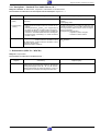
Einstellen des Neigungswinkels (Tilt)
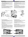
– Das Laufwerk in eine Feature-Funktion (z.B. Bildsuchlauf 7-fach
vorwärts) bringen.
– Mit der Schraube für den Neigungswinkel (Fig.19) die Bandunterkante gut auf die Bandführung "A1" aufsetzen (das Band darf nicht
an der Unterkante eingerollt sein).
Tilt Angle Adjustment
– Set the tape deck to a feature mode (e.g. picture search forward, 7times normal play).
– By means of the tilt angle adjusting screw (Fig. 19) move the tape
until the lower edge just touches the tape guide "A1" (the lower edge
of the tape must not bend).
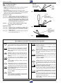
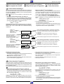
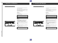
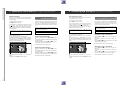
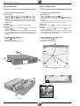
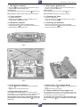
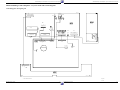
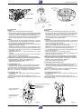
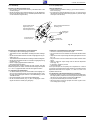
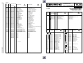
Höhen-Einstellschraube
Height setting screw
Neigungswinkel-Einstellschraube
Tilt setting screw
Azimut-Einstellschraube
Azimuth adjustment screw
Bandführung
A1 Tape guide
Capstan
Excenterschraube X
Eccentric screw X
Andruckrolle
Pressure roller
Band
Tape
Fig. 19
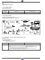
Einstellung des Azimutwinkels und der Kopfhöhe
– Oszilloskop an den Audioausgang anschließen.
– Testcassette mit dem Standardton-Audiosignal 400Hz wiedergeben.
– Mit der Höheneinstellschraube maximale Ausgangsspannung einstellen (Fig. 19).
– Testcassette mit dem Standardton-Audiosignal 8kHz wiedergeben.
– Mit der Azimuteinstellschraube auf maximale Ausgangsspannung
einstellen (Fig. 19).
– Diesen Vorgang gegebenenfalls wiederholen.
– Neigungswinkel kontrollieren.
Wenn der Bandlauf komplett verstellt war oder mehrere Teile des
Bandlaufes getauscht wurden, müssen die Einstellungen der Kapitel
3.1.1 und 3.1.2 gegebenenfalls mehrmals durchgeführt werden.
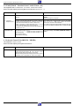
3.2 Einstellung des X-Abstandes
– Vor dieser Einstellung muß die Testcassette erneut eingelegt werden (von Eject-Stellung starten). Das Servicetestprogramm aufrufen (der Trackingwert geht dadurch in die Mittelstellung) und die
Taste J drücken.
– Den Schwarz/Weiß-Teil der Testcassette wiedergeben.
– Mit der Excenterschraube (Fig. 19) das Trackingsignal "TRIV"Signal auf Maximum stellen (DC-gekoppelt).
GRUNDIG Service-Technik
Adjustment of the Azimuth Angle and Height of the Head
– Connect an oscilloscope to the Audio output.
– Play the section of the test cassette with the 400Hz standard audio
signal.
– Adjust for maximum output voltage with the height adjustment screw
(Fig. 19).
– Play the section of the test cassette with the 8kHz standard audio
signal.
– Adjust to maximum output voltage with the azimuth adjustment
screw (Fig. 19).
– If necessary, repeat this process.
– Check the tilt angle.
If the tape transport was completely out of adjustment or if several
components in the tape path have been replaced, it is possible that the
adjustments described in the chapters 3.1.1 and 3.1.2 have to be
repeated several times.
3.2 Adjustment of the Horizontal Distance (x-distance)
– Before this adjustment, take out and reload the test cassette (start
from Eject position). Call the service test programme (tracking value
will take up its nominal position) and press the J button.
– Play back the black/white part of the test cassette.
– With the eccentric screw (Fig.19) adjust the "TRIV" signal to maximum voltage (DC-coupling).
5-9