1
Vectored Interrupt Controller
5
136
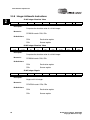
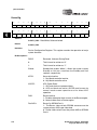
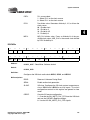
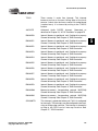
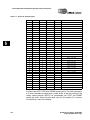
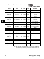
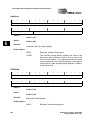
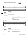
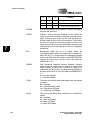
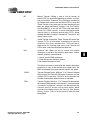
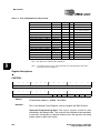
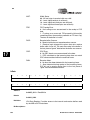
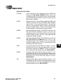
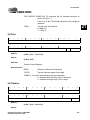
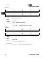
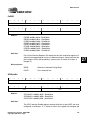
GPIO1INTR
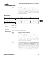
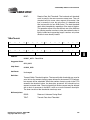
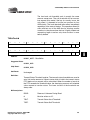
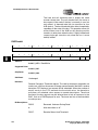
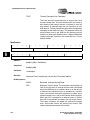
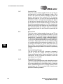
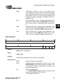
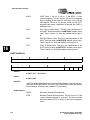
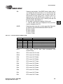
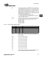
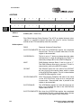
This interrupt is generated when port F bit 1 is configured
for interrupts. The interrupts can be configured to be level,
rising or falling edge sensitive. The interrupt is cleared by
writing to the GPIO end of interrupt location.
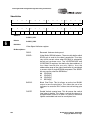
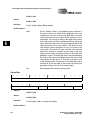
GPIO2INTR
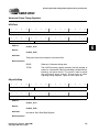
This interrupt is generated when port F bit 2 is configured
for interrupts. The interrupts can be configured to be level,
rising or falling edge sensitive The interrupt is cleared by
writing to the GPIO end of interrupt location.
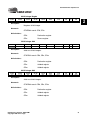
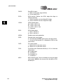
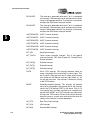
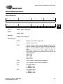
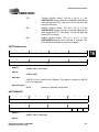
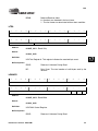
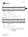
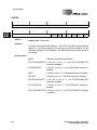
UART1RXINTR1
UART 1 receive interrupt.
UART1TXINTR1
UART 1 transmit interrupt.
UART1RXINTR2
UART 2 receive interrupt.
UART1TXINTR2
UART 2 transmit interrupt.
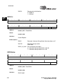
UART1RXINTR3
UART 3 receive interrupt.
UART1TXINTR3
UART 3 transmit interrupt.
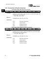
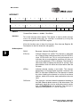
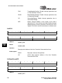
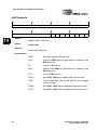
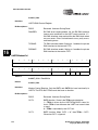
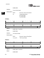
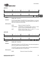
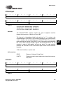
INT_KEY
Key Matrix Interrupt.
INT_TOUCH
Touch screen controller interrupt. This is the general
interrupt from the TSC. See Chapter 25, "Analog Touch
Screen Interface".
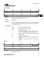
INT_EXT[0]
External interrupt.
INT_EXT[1]
External interrupt.
INT_EXT[2]
External interrupt.
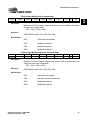
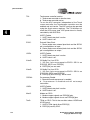
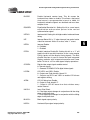
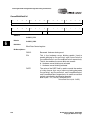
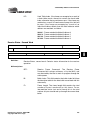
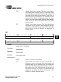
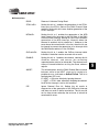
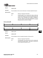
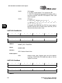
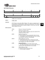
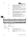
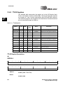
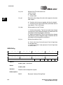
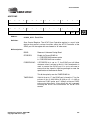
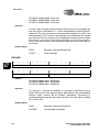
TINTR
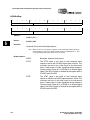
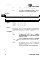
64 Hz TICK interrupt. This interrupt becomes active on
every rising edge of the internal 64 Hz clock signal. This
64 Hz clock is derived from the 15-stage ripple counter
that divides the 32.768 kHz oscillator input down to 1 Hz
for the real time clock. This interrupt is cleared by writing
to the TEOI location.
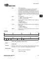
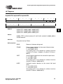
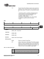
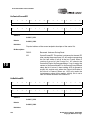
WEINT
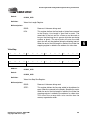
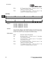
Watchdog expired interrupt. This interrupt will become
active on a rising edge of the periodic 64 Hz tick interrupt
clock if the TICK interrupt (TINT) is still active. That is, if a
tick interrupt has not been serviced for a complete tick
period. Both WEINT and TINT interrupts are cleared by
writing to the TEOI location. Failure to service this interrupt
does not cause a system reset and the action taken on
receipt of this interrupt is system dependent.
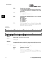
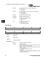
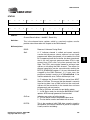
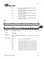
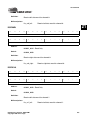
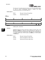
INT_RTC
Real Time Clock interrupt.
INT_IrDA
IrDA interrupt.
INT_MAC
Ethernet MAC interrupt.
EP9307 User’s Manual - DS667UM1
Copyright 2004 Cirrus Logic