1
6.2 Status Information
1) Buffer Memory BFM #28: Digital range error latch
BFM #29 b10(digital range error) is used to judge whether the measured temperature is within the
unit’s range or not.
BFM #28 latches the error status of each channel.
b15 or b8
b7
b6
High
Not used
b5
Low
b4
High
CH4
Low
b3
b2
High
CH3
Low
b1
High
CH2
8. EXAMPLE PROGRAM
10.EMC CONSIDERATIONS
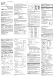
In the program shown below, the FX2N-4AD-PT block occupies the position of special block number 2 (that
is the third closest block to the PLC). The averaging amount is four. The averaged values in degrees C of
input channels CH1 to CH4 are stored respectively in data registers D0 to D3.
Electromagnetic compatibility or EMC must be considered before using the FX2N-4AD-PT.
b0
M8002
Low
Initialization
Pulse
CH1
FNC78
FROM
FNC10
CMP
Low : Latches ON when the temperature measurement data drops below the lowest
temperature measurement limit.
M8000
When an error occurs the temperature data before the error is latched. If the measured value returns
to within valid limits the temperature data returns to normal operation. (Note: The error remains
latched in (BFM #28))
An error can be cleared by writing K0 to BFM #28 using the TO instruction or turning off the power.
FNC78
FROM
D10
K2040 D10
K1
M0
K2
Y010
If some form of cable protection is used, the “Shield” must be terminated at the
as shown in section 4.1.
When (K2040) = (D10), M1 = ON
i.e. When identification code is K2040, M1 = ON
Because of the delicate nature of all analog signals, failure to take good EMC precautions could lead to
EMC noise induced errors; up to ±10% of actual values. This is an absolute worst case figure, users who
do take good precautions can expect operation within normal tolerances.
Represents b0 BFM #29
This step provides optional monitoring of the FX2N-4AD-PT Error Buffer Memory
(#29). If there is an Error on the FX2N-4AD-PT, bit b0 of BFM #29 will be set on.
This can be read by this program step, and output as a bit device in the PLC (Y010 in
this example). Additional Error devices can be output in a similar manner, i.e. b10 BFM
#29. (see below)
OFF
b0 : Error
When either b2 or b3 is ON
A/D conversion is stopped for
the error channel.
No error
b1 : Reserved
Reserved
Reserved
b2 : Power source
24V DC power supply failure.
Power supply normal
b3 : Hardware error
A/D converter or other
hardware failure.
Hardware Normal
b4 to b9 : Reserved
Reserved
Reserved
b10 : Digital range error
Digital output/analog input
value is outside the specified
range.
Digital output value is normal.
b11 : Averaging error
Selected number of averaged
results is outside the available
range -see BFM #1 to #4
Averaging is normal.
(between 1 to 4096)
b12 to b15 : Reserved
Reserved
Reserved
M8000
FNC78
FROM
M10
K2
K29
K4M10
K1
Y010
Represents b0 BFM #29
Y011
Represents b10 BFM #29
M20
M1
or
M8000
FNC79
TO
K2
K1
K4
K4
FNC78
FROM
K2
K5
D0
K4
FG
Block No.2 BFM #30 → (D10)
Identification code
Block No.2 BFM #29 → (K4M10)
Transfer the error status to (M25 to M10).
When error is found, M10 = ON.
K29 K4M10 K1
RUN
monitor M10
2) Buffer Memory BFM #29: Error status
ON
K30
This initial step checks that the special function block placed at position 2 is
actually an FX2N-4AD-PT, i.e. its unit identification number is 2040 (BFM #30).
This step is optional, but it provides a software check that the system has been
configured correctly.
High : Turns ON when the temperature measurement data rises above the highest
temperature measurement limit.
Bit devices of BFM #29
K2
Mitsubishi recommend that the PT 100 sensors used, should be fitted with a form of seild or screening as
protection against EMC noise.
terminals
EMC considerations should include selection of good quality cables, good routing of those cables away
from potential noise sources.
Additionally it is recommended that signal averaging is used as this will reduce the effects of random noise
“spikes”.
Attention
•
This product is designed for use in industrial applications.
Note
•
Manufactured by:
Mitsubishi Electric Corporation
2-7-3 Marunouchi, Chiyoda-ku, Tokyo, 100-8310 Japan
•
Manufactured at:
Mitsubishi Electric Corporation Himeji Works
840 Chiyoda-machi, Himeji, Hyogo, 670-8677 Japan
•
Authorized Representative in the European Community: Mitsubishi Electric Europe B.V.
Gothaer Str. 8, 40880 Ratingen, Germany
(K4) → (BFM #1 to #4)
Number of samples is changed to four on CH1 to CH4.
(BFM #5 to #8) → (D0 to D3)
Transfer the averaged temperature value in °C to the
data registers.
This step is the actual reading of the FX2N-4AD-PT input channels. It is essentially
the only program step which is needed. The "TO" instruction in this example, sets
the input channels, CH1 to CH4, to take the average reading of four samples.
The "FROM" instruction reads the average temperatures (BFM #5 to #8) for input
channels CH1 to CH4 of the FX2N-4AD-PT. If direct temperature readings are
required BFM #9 to #12 should be read instead, ex.
3) Buffer Memory BFM #30: Identification Code
The identification code or ID number for this Special Block is read from buffer memory BFM #30 using
the FROM instruction. This number for the FX2N-4AD-PT unit is K2040.
The PLC can use this facility in its program to identify the special block before commencing data
transfer from and to the special block.
FNC78
FROM
K2
K9
D0
K4
FX2N-4AD-PT result
special
No. of
block No.2 BFM number destination words read
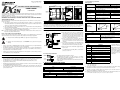
7. SYSTEM BLOCK DIAGRAM
9. DIAGNOSTICS
PLC
Command
information
write and
data status
read
POWER
5V Power
LED
Supply
TO
9.1 Preliminary checks
Gain and offset
values are
stored in the
EEPROM
Buffer
Memory
RAM
I.
Analog Input
Photocoupler
CPU
FROM
CH1
Converted
data
System
ROM
CH2
A/D
CH3
converter
Control
signals
CH4
Multiplexer
24V DC
Power Source
±15V
DC/DC
converter
FX2N-4AD-PT Analog Block
5V
5V
24V
LED
A/D
LED
Cyclic switching
Check whether the input/output wiring and/or extension cables are properly connected on the FX2N4AD-PT analog special function block.
II. Check that the PLC system configuration limits have not been exceeded, i.e. the number of special
function blocks, and the total system I/O are within the specified range.
III. Ensure that the correct operating range has been selected for the application.
IV. Check that there is no power overload on either the 5V or 24V power sources, remember the loading
on main unit or a powered extension unit varies according to the number of extension blocks or
special function blocks connected.
V. Make sure that the main unit has been switched to RUN.
9.2 Error checking
If the FX2N-4AD-PT special function block does not seem to operate normally, check the following items.
•
Check the status of the POWER LED.
Lit
:The extension cable is properly connected.
Otherwise :Check the connection of the extension cable.
•
Check the external wiring.
•
Check the status of the “24V” LED (top right corner of the FX 2N-4AD-PT).
Lit
:FX2N-4AD-PT is ON, 24V DC power source is ON.
Otherwise :Possible 24V DC power failure, if ON possible FX2N-4AD-PT failure.
•
Check the status of the “A/D” LED (top right corner of the FX2N-4AD-PT).
Lit
:A/D conversion is proceeding normally.
Otherwise :Check buffer memory #29 (error status). If any bits (b0, b2, b3) are ON, then this is why
the A/D LED is OFF.
This manual confers no industrial property rights or any rights of any other kind, nor does it confer any
patent licenses. Mitsubishi Electric Corporation cannot be held responsible for any problems involving
industrial property rights which may occur as a result of using the contents noted in this manual.
Manual number : JY992D65601
Manual revision : F
Date
: November 2010
HEAD OFFICE : TOKYO BUILDING, 2-7-3 MARUNOUCHI, CHIYODA-KU, TOKYO 100-8310, JAPAN
HIMEJI WORKS : 840, CHIYODA CHO, HIMEJI, JAPAN