1
363
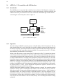
Priority
select
IRQ
Pending
Priority
encoder
APBI.PIRQ[15:1]
4
15
IRQO[0].IRL[3:0]
IRQ
IRQ
Force[0] mask[0]
Priority
encoder
4
IRQO[n].IRL[3:0]
IRQ
IRQ
Force[n] mask[n]
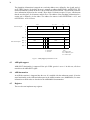
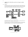
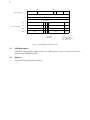
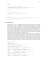
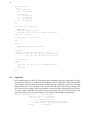
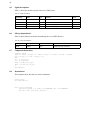
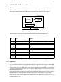
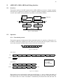
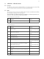
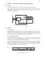
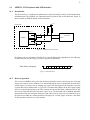
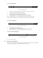
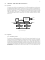
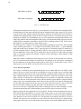
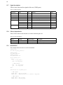
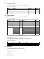
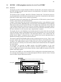
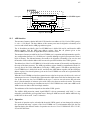
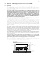
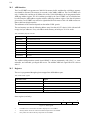
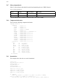
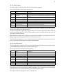
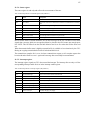
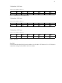
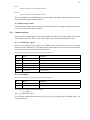
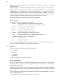
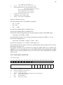
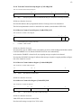
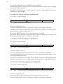
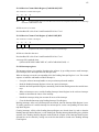
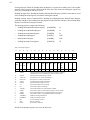
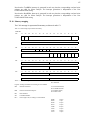
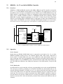
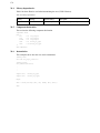
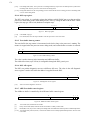
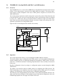
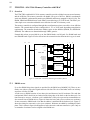
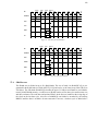
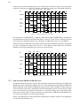
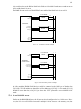
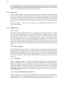
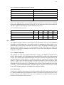
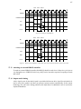
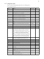
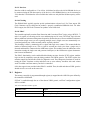
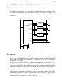
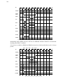
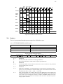
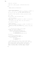
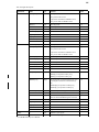
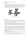
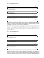
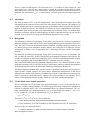
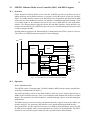
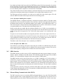
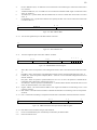
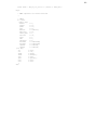
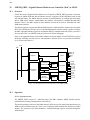
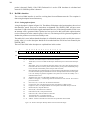
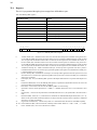
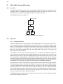
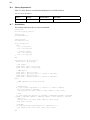
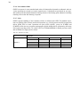
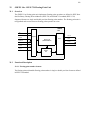
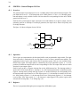
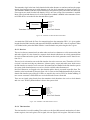
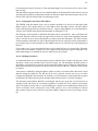
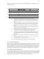
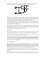
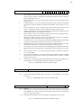
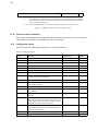
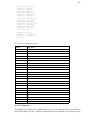
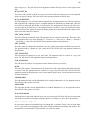
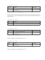
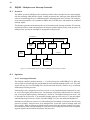
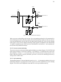
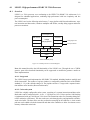
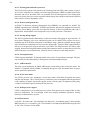
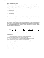
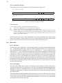
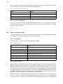
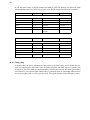
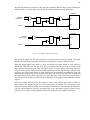
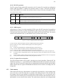
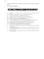
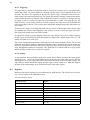
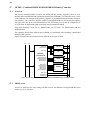
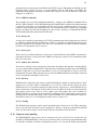
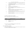
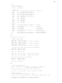
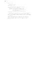
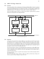
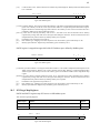
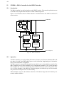
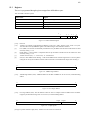
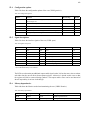
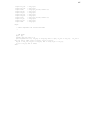
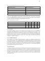
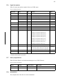
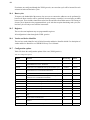
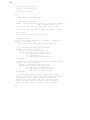
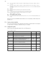
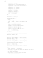
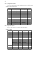
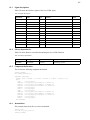
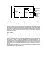
Figure 156. Interrupt controller block diagram
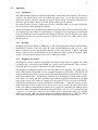
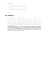
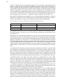
When a processor acknowledges the interrupt, the corresponding pending bit will automatically be
cleared. Interrupt can also be forced by setting a bit in the interrupt force register. In this case, the processor acknowledgement will clear the force bit rather than the pending bit. After reset, the interrupt
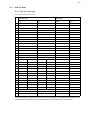
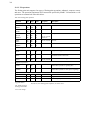
mask register is set to all zeros while the remaining control registers are undefined. Note that interrupt
15 cannot be maskable by the LEON3 processor and should be used with care - most operating systems do not safely handle this interrupt.
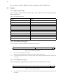
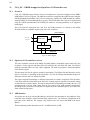
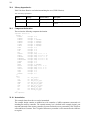
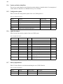
43.2.2 Processor status monitoring
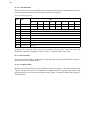
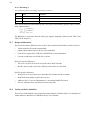
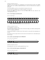
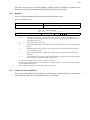
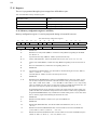
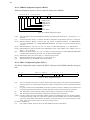
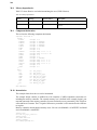
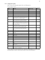
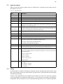
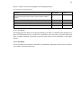
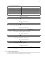
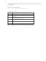
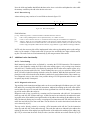
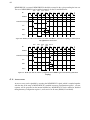
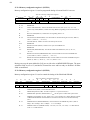
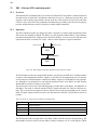
The processor status can be monitored through the Multiprocessor Status Register. The STATUS field
in this register indicates if a processor is halted (‘1’) or running (‘0’). A halted processor can be reset
and restarted by writing a ‘1’ to its status field. After reset, all processors except processor 0 are
halted. When the system is properly initialized, processor 0 can start the remaining processors by
writing to their STATUS bits.
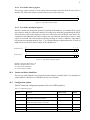
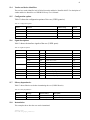
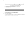
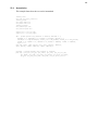
43.2.3 Irq broadcasting
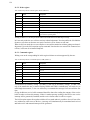
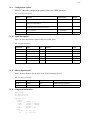
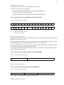
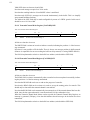
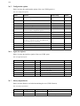
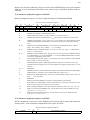
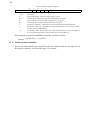
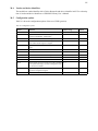
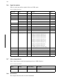
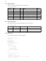
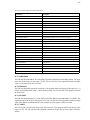
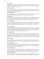
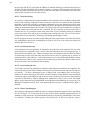
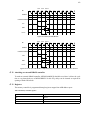
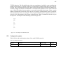
The Broadcast Register is activated when the generic ncpu is > 1. A incoming irq that has its bit set in
the Broadcast Register is propagated to the force register of all CPUs rather than only to the Pending
Register. This can be used to implement a timer that fires to all cpus with that same irq.