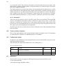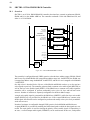
1
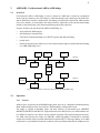
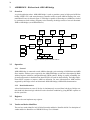
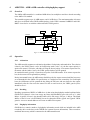
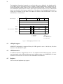
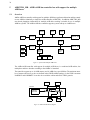
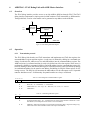
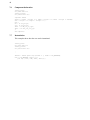
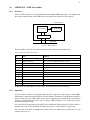
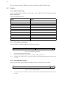
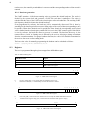
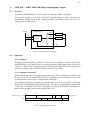
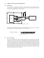
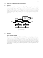
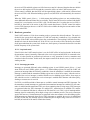
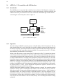
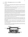
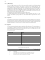
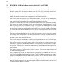
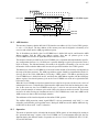
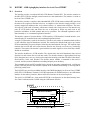
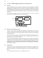
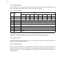
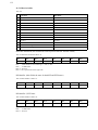
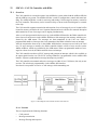
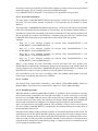
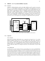
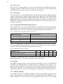
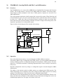
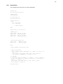
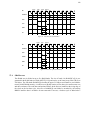
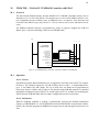
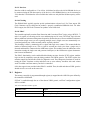
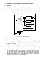
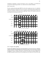
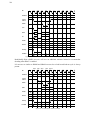
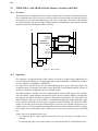
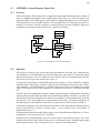
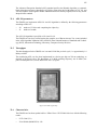
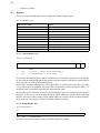
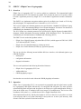
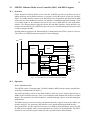
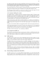
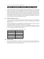
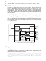
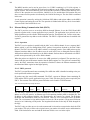
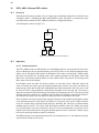
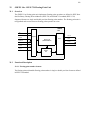
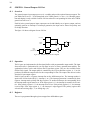
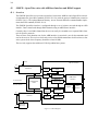
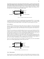
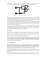
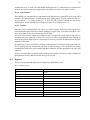
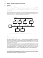
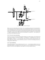
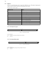
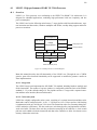
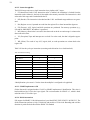
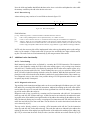
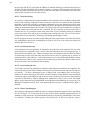
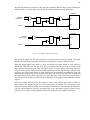
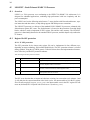
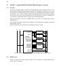
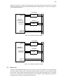
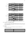
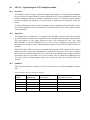
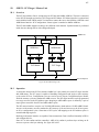
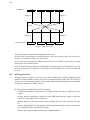
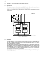
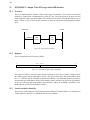
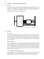
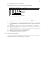
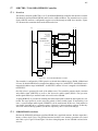
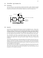
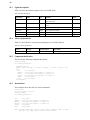
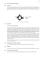
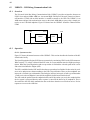
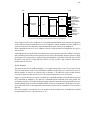
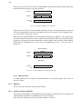
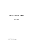
397
46
LOGAN - On-chip Logic Analyzer
46.1
Introduction
The LOGAN core implements an on-chip logic analyzer for tracing and displaying of on-chip signals.
LOGAN consists of a circular trace buffer and a triggering module. When armed, the logic analyzers
stores the traced signals in the circular buffer until a trigger condition occurs. A trigger condition will
freeze the buffer, and the traced data can then be read out via an APB interface.
The depth and width of the trace buffer is configurable through VHDL generics, as well as the number
of trigger levels.
On-chip Logic Analyzer core
Traced
signals
Trace buffer
Trigger engine
On-chip RAM
Write port
Control unit with
APB slave interface
Read port
AMBA APB
Figure 176. On-chip Logic Analyzer block diagram
46.2
Operation
46.2.1 Trace buffer
When the logic analyzer is armed, the traced signals are sampled and stored to the trace buffer on the
rising edge of the sample clock (TCLK). The trace buffer consists of a circular buffer with an index
register pointing to the next address in the buffer to be written. The index register is automatically
incremented after each store operation to the buffer.
46.2.2 Clocking
LOGAN uses two clocks: TCLK and the APB clock. The trace signals are sampled on the rising edge
of the sample clock (TCLK), while the control unit and the APB interface suse the APB clock. TCLK
and the APB clock does not need to be synchronized or have the same freqency.