1
!
FUEL LOG
INSTALLATION PLANNING
!
READ ME FIRST - Detailed Mechanical & Electrical Planning Saves Installation Hours!
FloScan K Series systems are not difficult to install. Installation requires only basic electrical & mechanical skills. With forethought
and planning, your system will be installed with few problems. Todd Walker, Yacht Electric Co., (954) 325-9091 regularly installs
FloScan K Series Twin Diesel Systems in about 10 hours. Difficult installations may take several hours longer.
I. Installation Preparation:
Review the pre-installation booklet, mechanical installation instructions, and survey your vessel. Determine where the Sensor(s),
Sensor Assemblies, Switches and Instruments are to be mounted. Place them at their approximate locations. Determine fitting size and
types required for each plumbing connection, (JIC, SAE, NPT, NPTF, or Hose Barb).
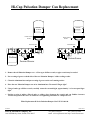
FloScan K-Series Hi-Cap Diesel Forward Sensor Assemblies have 1” Female NPT ports.
FloScan K-Series Hi-Cap Diesel Return Sensor Assemblies have 1” inlet and ½” outlet Female NPT ports.
FloScan Hi-Flo, (-10) Diesel and Gasoline Sensors have ½” Female NPT ports.
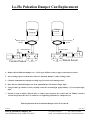
FloScan K-Series Lo-Flo Diesel and Gasoline System Components, (Sensors and Pulsation Dampers) have ¼” Female NPT ports.
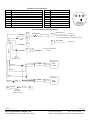
Review the electrical installation instructions. Open and survey your vessels wire ways. Determine if it would be easier to run a 3conductor cable from each sensor to the instrument, or install a junction box, (J-Box) with terminal strip in the engine room. The JBox requires a 4-conductor cable from it to the instrument, and a 3-conductor cable from each sensor. Measure cable lengths from
sensor(s) to J-Box, (If used) to Instrument. Tachometers require a separate 2-conductor cable. If there’s an existing tachometer, its
signal wires can be used.
II. Mechanical Installation:
Install or mount the Sensor(s) or Sensor Assemblies, Instruments and Switches, (Reset, MPG).
III. Plumbing:
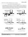
Most K Series and -10 installations do not require additional fuel hose. Mount the sensor(s) or sensor assemblies where they’re to be
installed. On installations using Fabric Braid A-1 Fuel Hose install the correct HB X MNPT fitting into each sensor or sensor
assembly. Always assemble fittings using a fuel proof pipe thread sealant. Never use Teflon Tape. Use a hose cutter or knife to cut
the fuel hose. Next install the hose onto the barb fittings. Hose should not be twisted, have adequate slack, an ample radius at all bends
and be supported at reasonable distances, approximately 2-4 feet. When clamping hose onto the barbs, use 2 narrow or 1 wide
stainless hose clamp on each hose end.
Wire Braid A-1 Aeroquip Type Fuel Hose or Hydraulic Hose: Mount the sensor(s) or sensor assemblies where they’re to be
installed. Mark the hose where it is to be cut. Remove hose and bring it to a hydraulic shop. Have them cut the hose and install hose
ends. Reinstall the hoses and install the correct fitting into each sensor or sensor assembly. Always assemble fittings using a fuel proof
pipe thread sealant. Never use Teflon Tape. Hoses should not be twisted, have adequate slack, an ample radius at all bends and be
adequately supported at reasonable distances, approximately 2-4 feet. AP-50 copper sealing washers, (Connie Seals) or Flaretite seals
may be required to seal JIC & SAE fittings.
IV. Electrical Installation:
Run cables between Sensor(s), J-Box, (If used) and Instrument(s). Cables must be adequately supported at reasonable distances,
approximately 2-4 feet.
Wire Terminations—Referring to the wiring diagram. Connect Sensor, Instrument and Switches to their respective wires with crimp
type butt or ring connectors. Always cover connectors and wire ends with heat shrink tubing.
12/8/2004
FloScan Instrument Company, Inc.
3016 NE Blakeley Street, Seattle, WA 98105
7000-339-00
Tel: (206) 524-6625
Fax: (206) 523-4961
email: [email protected] http://www.floscan.com