1
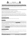
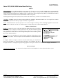
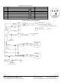
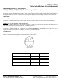
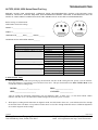
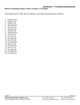
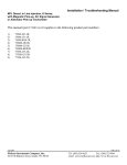
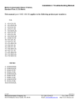
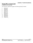
WIRING DIAGRAM
Series 8500/8600 Pulse Output Diesel Fuel Log
Instrument Connection Harness
FUNCTION
PIN #
RED Not Connected (twin applications see note below)
9
RED/WHITE + pulse out
10
WHITE/YELLOW +pulse in (Twin applications)
11
ORANGE Illumination + 12VDC
12
BLACK Instrument Ground
13
WHITE Forward Flow Sensor signal
14
GREEN/BLACK (-) pulse out
15
YELLOW Not Connected
16
PIN #
1
2
3
4
5
6
7
8
FUNCTION
RED + 12VDC
GREEN Totalizer Reset
Not Connected
BLACK Jumper to pin # 13
BLACK Jumper to pin # 12
BROWN Not Connected
BLACK Reset Ground
VIOLET Not Connected
0
0
BLACK
0
RED
E
GREEN
F 0
1
2
D
C
B
3
4
5
A
9
8 7
6
16 15 14 13 12 11 10 9
8
7
6
5
4
3
2
1
BACK OF INSTRUMENT
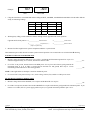
Single Sensor Installations
RED
6
WHITE
CABLE
1/2 amp fuse
9
BLACK
4
ORANGE
To Ignition Switch
(Key ON = + 12VDC)
10
GREEN
To + Panel Illumination
+ 12VDC
BLACK
15
Totalizer
Reset Switch
(momentary ON)
5
Battery (-) buss
BLACK
B
R
R
B
W
CABLE
B
W
Flow
Sensor
WHITE
RED
7
2
GREEN/BLACK
(-) Pulse Out
To External Computer (if applicable)
RED/WHITE
(+) Pulse Out
NOTE: This diagram is used for Diesel systems requiring only one (1) sensor in the fuel system.
12/8/2004
FloScan Instrument Company, Inc.
3016 NE Blakeley Street, Seattle, WA 98105
7000-338-00
Tel: (206) 524-6625
Fax: (206) 523-4961
email: [email protected] http://www.floscan.com