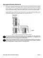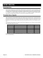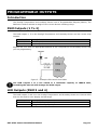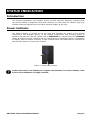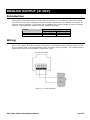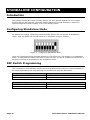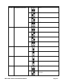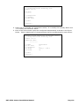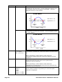
1
PRT-ATH1
Temperature and Humidity
Sensor
Installation Manual
PUBLICATION INFORMATION
This manual covers firmware versions 1.40 or higher of the Protégé Temperature and Humidty Sensor when operating on
hardware revision 208-4185-020 or higher. Specifications may change without notice, for updates visit the Integrated Control
Technology website at www.integratedcontroltechnology.com
COPYRIGHT NOTICE
Integrated Control Technology has granted the following specific permissions for the electronic version of this manual:
1.
Permission is granted to retrieve, print and store a single copy of this manual for personal use for the
express purpose of servicing, installing or maintaining products from Integrated Control Technology.
This permission does not extend to photocopying or producing copies in any form what so ever for other
than personal use of the person creating the copy, or making electronic copies available for retrieval by
others in any form without prior permission in writing from an officer of Integrated Control Technology.
Except where over-ridden by the specific permission above, the standard copyright notice from Integrated Control
Technology applies to the electronic version:
1.
2.
Neither this manual nor any part may be reproduced or transmitted in any form or by any means,
electronic or mechanical, including photocopying, microfilming, and recording, or by any information
storage or retrieval system, without prior permission in writing from the publisher.
The consent of Integrated Control Technology does not extend to copying for general distribution, for
promotion, for creating new works, or for resale. Specific permission must be obtained in writing from
an officer of Integrated Control Technology for such copying.
PRT-ATH1 Sensor Installation Manual
Page 1
CONTENTS
Contents........................................................................ 2
Protégé System ............................................................. 4
Introduction ..................................................................................................................... 4
Temperature and Humidity Sensor ...................................................................................... 4
Features .......................................................................................................................... 4
Temperature and Humidity Sensor Specifications................................................................... 5
Protégé System Management Suite ..................................................................................... 6
Protégé Modules ............................................................................................................... 6
Installation.................................................................... 8
Package Contents ............................................................................................................. 8
Wire Loom Colour Coding ................................................................................................... 8
Encrypted Module Network ........................................... 9
Zone Inputs................................................................. 10
Introduction ....................................................................................................................10
Trouble Zone Inputs .........................................................................................................10
Programmable Outputs ............................................... 11
Introduction ....................................................................................................................11
PGM Outputs (1 To 2).......................................................................................................11
LED Outputs (PGM 3 and 4)...............................................................................................11
Configuration Switch ................................................... 12
Introduction ....................................................................................................................12
Address Configuration.......................................................................................................12
Status Indication......................................................... 13
Introduction ....................................................................................................................13
Power Indicator ...............................................................................................................13
Error Code Indication .................................................. 14
Introduction ....................................................................................................................14
Error Code Display ...........................................................................................................14
Analog Output (0-10V)................................................ 15
Introduction ....................................................................................................................15
Wiring ............................................................................................................................15
Standalone Configuration ............................................ 16
Introduction ....................................................................................................................16
Configuring Standalone Mode ............................................................................................16
DIP Switch Programming ..................................................................................................16
Programming Output Alarms .............................................................................................18
Ordering Information .................................................. 22
Page 2
PRT-ATH1 Sensor Installation Manual
Product Codes .................................................................................................................22
Warranty ..................................................................... 23
Introduction ....................................................................................................................23
Contact ..........................................................................................................................23
PRT-ATH1 Sensor Installation Manual
Page 3
PROTÉGÉ SYSTEM
Introduction
The Protégé System is a powerful integrated alarm and access control management system
designed to provide integration with building automation, apartment complex control and
HVAC in one flexible package. Communicating through a proprietary high speed protocol
across an encrypted RS-485 network using modular-based hardware design, system installers
have the flexibility to accommodate any installation from small or large, residential or
commercial.
Temperature and Humidity Sensor
The PRT-ATH1 Protégé Temperature and Humidity Sensor extends the Protégé System by
providing Temperature, Humidity and Dew Point readings that can be used for building
automation and control or environmental alarms. The Protégé Temperature and Humidity
Sensor can monitor the environmental conditions of highly critical server rooms, this data can
be used to control the air conditioning in the room to maintain regulated conditions. Protégé
can also use the data to trigger reportable alarms when normal operating conditions are
exceeded to enable a prompt response to any problems.
Flexible module network architecture allows large numbers of modules to be connected to the
RS-485 Module Network. Up to 250 modules can be connected to the Protégé System in any
combination to the network up to a distance of 900M (3000ft). Communication beyond this
distance requires the use of a RS-485 Module Network Repeater (PRT-MNR4) or the Slave
Communication port of the PRT-RDI2 Intelligent Reader Expander.
Securing a network prevents the removal, substitution or addition of modules to the module
network effectively preventing any tampering with the system.
Features
•
•
•
•
•
•
•
•
•
Page 4
-40˚C to 120˚C Temperature Sensor (±0.1˚C)
0% to 100% Humidity Sensor (±3.0%)
Isolated Secure Encrypted RS-485 Module Communications
Channel differentiate send on event per channel.
Channel deviation trigger level.
2 Low Current PGM Outputs
2 Display LED PGM Outputs
8-30VDC Input Power Supply
Online and Remote upgradeable firmware
PRT-ATH1 Sensor Installation Manual
Temperature and Humidity Sensor Specifications
The following specifications are important and vital to the correct operation of the
PRT-ATH1 Protégé Temperature and Humidity Sensor. Failure to adhere to the
specifications will result in any warranty or guarantee that was provided becoming
null and void.
Integrated Control Technology continually strives to increase the performance of its products
and as a result the specifications may change without notice. It is recommended that you
always consult www.integratedcontroltechnology.com for the latest documentation and
product information.
Power Supply
DC Input Voltage
Operating Current
Sensors
Temperature
Humidity
12VDC (8-30VDC)
20mA (Typical)
-40˚C to 120˚C (±0.1˚C)
-40˚F to 250˚F (±0.2˚F)
0% to 100% (±3.0%)
Communication
RS-485
Non-Isolated Module Network
Outputs
PGM Outputs
LED Outputs
2 (100mA Max) Relay Outputs
2 Configurable LED Indicators
Inputs
Trouble Zone
8
Dimensions
Plastic
Temperature
Operating
Humidity
Storage
PRT-ATH1 Sensor Installation Manual
75mm x 118mm X 19mm
3" x 4.6" x 0.7"
5˚- 55˚ Celsius
41˚ - 131˚ Fahrenheit
0%-85% (Non-Condensing)
-10˚- 85˚ Celsius
14˚ - 185˚ Fahrenheit
Page 5
Protégé System Management Suite
The Protégé System Management Suite is a Windows 2000/XP Professional Integrated Access
Control and Alarm Management system designed for any configuration from single site, single
controller applications up to the global multi-national corporations using multiple site, multiple
controller installations.
The Protégé System Management Suite application is ideal for the configuration and
management of your Protégé installation. Special built in features and the quick-start kit will
get your system up and running in minutes.
Protégé Modules
The Protégé System can be expanded to accommodate large numbers of modules using the
encrypted RS-485 network. Modules that are currently available are listed below. Visit the
Integrated Control Technology website www.integratedcontroltechnology.com for the latest
Protégé module and product information.
Alphanumeric LCD User Interface (PRT-KLCD)
The Protégé LCD User Interface Keypad is the interface between the user and the
Protégé System. All programming and end user functions can be performed using the
LCD Keypad. The 32 character alphanumeric display uses easy to read messages and
menus to guide users through the systems operation. The LCD Keypad also adds two
zones (four zones in multiple zone configuration) and one PGM to the Protégé System.
16 Zone Expansion Module (PRT-ZX16)
Extends the Protégé System with the addition of 16 Zones and 4 Programmable
Outputs (PGM's). Operates from 16VAC with onboard power supply and isolated
communication interface.
16 Zone Standard Expansion Module (PRT-ZXS16)
Extends the Protégé System with the addition of 16 Zones and 1 Programmable Output
(PGM). Operates from 12VDC network connection. No onboard power supply.
16 PGM Expansion Module (PRT-PX16)
Extends the Protégé System with the addition of 16 Programmable Outputs (PGM's)
(16 7A FORM C Relays). The PRT-PX16 can be connected to the slave communications
interface of the PRT-RDI2 2 Reader Expansion Module for FULL monitored elevator
control with the addition of the PRT-DRI Destination Reporting Interface Optical Input
Module.
16 PGM Standard Expansion Module (PRT-PXS16)
Extends the Protégé System with the addition of 16 Programmable Outputs (PGM's)
(16 20mA Open Collector Outputs). Operates from 12VDC network connection. No
onboard power supply.
Ethernet Intelligent 2 Reader Expansion Module (PRT-RDE2)
Communicating over a high speed interface using 10/100 Ethernet, interface
connection for two card readers, either Wiegand or Magnetic Stripe formats. Four
Wiegand Card Readers can be connected in Multiple Card mode. The 2 Reader Ethernet
Expansion Module also adds 8 Zones and 8 Outputs to the Protégé System. Some of
the outputs on the PRT-RDE2 have specific access control functions and can be used as
zones in the Protégé alarm processing functions.
Intelligent 2 Reader Expansion Module (PRT-RDI2)
Page 6
PRT-ATH1 Sensor Installation Manual
Adds the interface connection for two card readers, either Wiegand or Magnetic Stripe
formats. Four Wiegand Card Readers can be connected in Multiple Card mode. The 2
Reader Expansion Modules also adds 8 Zones and 8 Outputs to the Protégé System.
Some of the outputs on the PRT-RDI2 have specific access control functions and can be
used as zones in the Protégé alarm processing functions.
Mini 2 Reader Expansion Module (PRT-RDM2)
Adds the interface connection for two card readers, either Wiegand or Magnetic Stripe
formats. Four Wiegand Card Readers can be connected in Multiple Card mode. The 2
Reader Expansion Modules also adds 6 Zones and 8 Outputs to the Protégé System.
Some of the outputs on the PRT-RDM2 have specific access control functions and can
be used as zones in the Protégé alarm processing functions.
Analog 4 Channel Input Expansion Module (PRT-ADC4)
Protégé allows the connection of the latest building automation technology and
completely integrated building automation solutions. Adds 4 Analog Inputs (4-20mA or
0-10V) allowing the connection of numerous industrial automation sensors. The Analog
Input Expansion Modules also adds 4 PGM Outputs to the Protégé System.
Analog 4 Channel Output Expansion Module (PRT-DAC4)
Protégé allows the connection of the latest building automation technology and
completely integrated building automation solutions. Adds 4 Analog Outputs (4-20mA
or 0-10V) allowing the connection of numerous industrial automation outputs including
air damper and sun louver controls as well as analog flow valves. The Analog Output
Expansion Modules also adds 4 PGM Outputs to the Protégé System.
PRT-ATH1 Sensor Installation Manual
Page 7
INSTALLATION
Package Contents
When receiving the PRT-ATH1 Protégé Temperature and Humidity Sensor you should find the
kit contains the items listed below. The kit type is clearly labeled on the packaging and will tell
you what your kit contains. Please note that if you do not have the correct contents contact
your distributor immediately.
PRT-ATH1
Contents:
Protégé Temperature and Humidity Sensor
Temperature and Humidity Sensor
10 Way Wiring Loom
Wire Loom Colour Coding
The Protégé Temperature and Humidity Sensor is supplied with a wire loom attachment and
are connected using a keyed 10 position snap lock connector. The 10 way wiring loom
connection uses the following colour coding.
Figure 1 - Wiring Loom Colour Coding
Page 8
PRT-ATH1 Sensor Installation Manual
Encrypted Module Network
The Protégé Temperature and Humidity Sensor incorporate encrypted RS-485 communications
technology. Connection of the communications should be performed according to the diagram
shown in Figure 2. It is important that the N+ Network Communications Power be supplied
from an independent battery backed power supply unit or a networked module capable of
supplying the required voltage to all of the network powered devices on the RS485 network.
Always connect the modules NA and NB terminals to the NA and NB terminals of the
communication network. The N+ and N- must go to a 12V power supply source as shown in
the following diagram and connected at ONLY one +12V power source.
Figure 2 - Network Power Supplied By Network Module
The 12V N+ and N- Communication input must be supplied from only ONE point.
Connections from more than one 12V supply may cause failure or damage to the
reader expander or device supplying network power.
Under no circumstances should you power the locking devices that are connected to
the PRT-ATH1 from the N+ and N- network communication power supply. A separate
power supply MUST be used to power the locking devices.
PRT-ATH1 Sensor Installation Manual
Page 9
ZONE INPUTS
Introduction
The Protégé Temperature and Humidity Sensor have no physical zone input connections. The
Temperature and Humidity Sensor monitors 8 trouble zones used to report trouble conditions.
A trouble zone is in most cases not physically connected with an input in to the Sensor; rather
it is related to a status condition within the system. For example a module communication
fault causes a trouble zone to open as a result of the communication failure.
Trouble Zone Inputs
Each Temperature and Humidity Sensor can monitor up to 8 trouble zones. Trouble zones are
used to monitor the status of the Temperature and Humidity Sensor and in most cases are not
physically connected to an external zone input. For example, trouble zone AE001:02 is used
to monitor the analog supply voltage output and will generate an alarm if the voltage is low or
fails.
The following table details the trouble zones that are configured in the system and the trouble
type and group that they activate.
Zone Number
AExxx:01
AExxx:02
AExxx:03
AExxx:04
AExxx:05
AExxx:06
AExxx:07
AExxx:08
Description
Reserved
Power Supply Voltage Low
Reserved
Reserved
Reserved
Reserved
Reserved
Module Offline
Type
None
Power Fault
None
None
None
None
None
Module Offline
Group
None
General
None
None
None
None
None
System
Replace the 'xxx' with the appropriate address of the Temperature and Humidity Sensor that
you are programming.
Page 10
PRT-ATH1 Sensor Installation Manual
PROGRAMMABLE OUTPUTS
Introduction
The Protégé Temperature and Humidity Sensor have 4 Programmable Outputs (PGM's). The
PGM's are used to activate a range of low current devices including relays.
PGM Outputs (1 To 2)
The PGM outputs 1, 2 on the Protégé Temperature and Humidity Sensor are low current relay
outputs.
PGM Number
AExxx:01
AExxx:02
Description
PGM Output 1
PGM Output 2
Replace the 'xxx' with the appropriate address of the Temperature and Humidity Sensor that
you are programming.
Figure 3 - Example LED Control from PGM 1
The PGM outputs 1 to 2 can switch to a maximum capacity of 100mA each,
exceeding this amount will damage the PGM output.
LED Outputs (PGM 3 and 4)
The PGM outputs 3 and 4 on the Protégé Temperature and Humidity Sensor are internal LEDs
that can be used for user display and warnings.
PGM Number
AExxx:03
AExxx:04
Description
Square LED Output (Center)
Triangle LED Output (Left)
PRT-ATH1 Sensor Installation Manual
Page 11
CONFIGURATION SWITCH
Introduction
The addressing of the Protégé Temperature and Humidity Sensor allows up to 128 devices to
be connected to the Protégé System Controller. The 'CONFIG' configuration DIP switch allows
each Temperature and Humidity Sensor to have a unique address.
Address Configuration
The switch positions 1 to 7 select the device address from 1 to 128. When setting an address
the Temperature and Humidity Sensor must be powered down and restarted for the new
address to take affect. When changing the address the Temperature and Humidity Sensor will
automatically default the internal configuration and require a network update. See the Protégé
System reference manual for information on performing a module update.
Figure 13 - Temperature and Humidity Sensor CONFIG Switch Functions
The device address is determined by adding the value of each switch that is selected in the
ON position and then adding 1 to this value. In the example below the address 024 results in
(16+4+2+1) + 1 = 024. Setting all address switches to OFF results in the default address of
001.
Figure 14 - Temperature and Humidity Sensor Configured For Address 024
Page 12
PRT-ATH1 Sensor Installation Manual
STATUS INDICATION
Introduction
The Protégé Temperature and Humidity Sensor includes extensive diagnostic indicators that
can aid the installer in diagnostic faults and conditions. In some cases an indicator may have
multiple meanings depending on the status indicator display at the time.
Power Indicator
The Power Indicator is located at the top right and indicates the status of the Protégé
Temperature and Humidity Sensor. If the Protégé Temperature and Humidity Sensor is
operating normally the LED will indicate this by FLASHING at 1 second intervals. FLASHING
rapidly at 250ms intervals indicates that the Temperature and Humidity Sensor is attempting
to register with the system controller, or that communication has failed and the Temperature
and Humidity Sensor is retrying the request.
Figure 4 - Power LED Location
If the power LED is not flashing at a regular interval there is a fault condition, refer
to Error Code Indication on page 14 below.
PRT-ATH1 Sensor Installation Manual
Page 13
ERROR CODE INDICATION
Introduction
When the Temperature and Humidity Sensor attempts to register or communicate with the
system controller a registration error can be generated indicating that it was not successful.
Error Code Display
The following table is only valid if the FAULT indicator is ON and the STATUS indicator is
FLASHING. If the fault indicator is FLASHING the Temperature and Humidity Sensor
requires a firmware update or is currently in firmware update mode.
The status indicator will FLASH with the error code number. The error code number is shown
with a 250ms ON and OFF period (duty cycle) with a delay of 1.5 seconds between each
display cycle.
FLASH
1
2
3
4
5
6
7
8
Page 14
ERROR DESCRIPTION
Unknown Error Code
The error code returned by the system controller could not be
understood by the Analog Expander. Contact Integrated Control
Technology.
Firmware Version
The firmware version on the Temperature and Humidity Sensor is not
compatible with the system controller. To clear this error, update the
module using the module update application.
Address Too High
The Temperature and Humidity Sensor address is above the maximum
number of Analog Expanders available on the system controller. To
clear this error change the address to one within the range set on the
system controller, restart the Temperature and Humidity Sensor by
disconnecting the power.
Address In Use
The Address is already in use by another Analog Expander. To clear
this error set the address to one that is currently not occupied by a
Analog Expander. Use the view network status command to list the
attached devices, or the network update command to refresh the
registered device list.
Controller Secured Registration Not Allowed
Controller is not accepting any module registrations. To allow module
registrations use the network secure command to change the secure
setting to not secured.
Serial Number Fault
The serial number in the device is not valid. Return the unit to the
distributor for replacement.
Locked Device
The Temperature and Humidity Sensor or system controller is a locked
device and can not communicate on the network. Return the unit to
the distributor for replacement.
Virtual Module
This address has been reserved as a virtual module and therefore no
module can register at this address. This protects programming of
zones and PGM that are used internally by programmable functions.
PRT-ATH1 Sensor Installation Manual
ANALOG OUTPUT (0-10V)
Introduction
The Protégé Temperature and Humidity Sensor also has a 0-10V analog output that follows
the current value of the Temperature and Humidity input allowing the Sensor to interface to
external control systems. This output will be updated even when operating with the Protégé
System. The table below details what the voltages represent.
Sensor
Analog Value
0V
10V
Temperature (Yellow)
-50˚C (-58˚F)
50˚C (122˚F)
Humidity (Gray)
0%
100%
Table 1 - 0-10V Analog Output Values
Wiring
The 0-10V outputs from the Protégé Temperature and Humidity Sensor can be directly wired
into an analog input of a Programmable Logic Controller (PLC) or similar. The example below
shows how to wire the temperature output into a PLC.
Figure 5 - 0-10V Interface
PRT-ATH1 Sensor Installation Manual
Page 15
STANDALONE CONFIGURATION
Introduction
The Protégé Temperature and Humidity Sensor can also operate separate of the Protégé
System and can activate the 4 onboard outputs based on internal settings or output the
current temperature and humidity on a 0-10V analog output.
Configuring Standalone Mode
By default the Protégé Temperature and Humidity Sensor will not operate in Standalone
mode. With the power off set DIP switch 8 on as shown in Figure 6 below.
Figure 6 - Configuring Standalone Mode
When the Temperature and Humidity Sensor is next turned on it will operate in a standalone
mode. In this mode the Power LED will not flash on start up, but all 3 LEDs will activate for 5
seconds to confirm it is operating in the standalone mode.
DIP Switch Programming
The Temperature and Humidity Sensor can be programmed from either the Serial interface or
for simple applications the programming can be achieved using the DIP switch.
Temperature Setting
Output
Hysteresis
Table 1 - Fixed Temperature
Setup
Relay 1 + LED 1
2˚C
Settings in DIP Switch Mode
Humidity Setting
Setup
Output
Relay 2 + LED 2
Hysteresis
5%
Table 2 - Fixed Humidity Settings in DIP Switch Mode
Page 16
PRT-ATH1 Sensor Installation Manual
Switch
1–2
Variable
Temperature Set Point
Setting
Action
22˚C
4˚C
10˚C
26˚C
3–4
Humidity Set Point
60%
40%
50%
70%
5
Alarm Mode
Alarm Above
Alarm Below
6
Invert Outputs
None
Invert
7-8
Standalone Mode
Protégé Mode
Standalone Mode uses Serial Port
Settings
PRT-ATH1 Sensor Installation Manual
Page 17
Standalone Mode uses DIP Switch
Settings
Table 3 - Standalone DIP Switch Settings
Programming Output Alarms
For more complex systems that where the require setup can not be achieved using the DIP
switch programming show above the Protégé Temperature and Humidity Sensor can be
programmed using a serial connection from a PC Computer. Both the Temperature and
Humidity inputs have independently configurable set points that can activate the relay outputs
when they are exceeded.
These are configured using Hyper-Terminal (or TeraTerm) on a PC Computer.
1. Using a RS-232 to RS-485 converter (like the ACC-485 from Integrated Control
Technology) connect the Temperature and Humidity Sensor to a Serial Port.
Figure 7 - Wiring Connection for Serial Programming
2. Open Hyper-Terminal and make a connection using a baud rate of 38400, 8 data bits,
no parity bit, 1 stop bit and no flow control (38400,8,n,1).
3. Press ESC and the following screen will appear.
Because Dew Point (measured in ˚C) is a function of Temperature and Humidity
the Protégé Temperature and Humidity Sensor can also calculate this value. This
may be useful in some installations.
Page 18
PRT-ATH1 Sensor Installation Manual
PRT-ATH1 Protégé Temperature and Humidity Sensor
(c) Integrated Control Technology 2008
Version 1.02.67
Main Menu
--------[a] Temperature
[b] Humidity
[c] Dew Point
[x] Exit
Selection >
4. Select the ‘a’ to modify the Temperature alarm, ‘b’ to modify the Humidity alarm and
‘c’ to modify the Dew Point Alarm.
5. Each of the three sensor inputs are configured independently as shown in the figure
below. Table 2 details each of the parameters that are programmed for each sensor.
PRT-ATH1 Protégé Temperature and Humidity Sensor
(c) Integrated Control Technology 2008
Version 1.02.67
Temperature Menu
----------[a]
[b]
[c]
[d]
[e]
Mode
Set Point
Hysteresis
Output
Invert
Alarm Above
20
2
Relay 1 + LED 1
No
[x] Exit
Selection >
PRT-ATH1 Sensor Installation Manual
Page 19
Variable
Mode
Values
Alarm Above
Definition
The mode determines when the output will be activated
compared to the set point. In this mode the output(s) will
be activated when the set point is exceeded. See the
diagram below for more details.
ALARM ABOVE
20
Set Point = 20
18
Hysteresis = 2
Output
ON
Output
OFF
Time
Alarm Below
In alarm below mode the output(s) are activated when the
temperature is below the set point. See the diagram below
for more details.
ALARM BELOW
10
Set Point = 4
4
Hysteresis = 6
Output
ON
Output
OFF
Time
Set Point
Hysteresis
Output
Page 20
T: -40 to 100
H: 0-100%
DP: -40 to 100
0-255
Relay 1
Relay 2
LED 1
LED 2
Relay 1 + LED 1
Relay 2 + LED 2
When operating in ‘Alarm Above’ mode when the
temperature exceeds this value the output(s) will be turned
on.
When operating in ‘Alarm Below’ mode when the
temperature drops below this value the output(s) will be
turned on.
When operating in ‘Alarm Above’ when the temperature
drops below the Set point minus the hysteresis the
output(s) will be turned off.
When operating in ‘Alarm Below’ mode when the
temperature exceeds the Set point plus the hysteresis the
output(s) will be turned off.
Select the output that is activated when the sensor goes
into an alarm condition by pressing ‘d’ until the output
required is displayed.
PRT-ATH1 Sensor Installation Manual
Invert
No
Yes
The state of the output(s) can be inverted when this option
is set to ‘Yes’. Press ‘e’ to select the required option. When
the invert option is selected the output will be turned off
when the sensor is in alarm.
Table 2 - Standalone Programming Options
6. Once the programming is complete, press ‘x’ to return to the main menu and program
the other sensors.
PRT-ATH1 Sensor Installation Manual
Page 21
ORDERING INFORMATION
Product Codes
Please use the following product codes when placing an order for the Protégé Temperature
and Humidity Sensor.
PRT-ATH1-PCB
Protégé Temperature and Humidity Sensor
Includes
Accessory Bag
Manuals and literature are available at the Integrated Control Technology website in the
documentation section. If you require manuals on CD-ROM please request a literature CDROM from the website.
Page 22
PRT-ATH1 Sensor Installation Manual
WARRANTY
Introduction
The Protégé Temperature and Humidity Sensor are covered under the Integrated Control
Technology standard terms and warranty agreement. This document can be downloaded from
the Integrated Control Technology web site or obtained by return fax.
Contact
Integrated Control Technology welcomes all feedback. Please visit our website or use the
information below.
Integrated Control Technology
P.O. Box 302-340
North Harbour Post Centre
Auckland
New Zealand
Phone:
Fax:
Unit C,
6 Ascension Place
Mairangi Bay
Auckland
New Zealand
+64-9-476-7124
+64-9-476-7128
www.integratedcontroltechnology.com
PRT-ATH1 Sensor Installation Manual
Page 23
NOTES
________________________________________________________________________________
________________________________________________________________________________
________________________________________________________________________________
________________________________________________________________________________
________________________________________________________________________________
________________________________________________________________________________
________________________________________________________________________________
________________________________________________________________________________
________________________________________________________________________________
________________________________________________________________________________
________________________________________________________________________________
________________________________________________________________________________
________________________________________________________________________________
________________________________________________________________________________
________________________________________________________________________________
________________________________________________________________________________
________________________________________________________________________________
________________________________________________________________________________
________________________________________________________________________________
________________________________________________________________________________
________________________________________________________________________________
________________________________________________________________________________
________________________________________________________________________________
________________________________________________________________________________
________________________________________________________________________________
Page 24
PRT-ATH1 Sensor Installation Manual
NOTES
________________________________________________________________________________
________________________________________________________________________________
________________________________________________________________________________
________________________________________________________________________________
________________________________________________________________________________
________________________________________________________________________________
________________________________________________________________________________
________________________________________________________________________________
________________________________________________________________________________
________________________________________________________________________________
________________________________________________________________________________
________________________________________________________________________________
________________________________________________________________________________
________________________________________________________________________________
________________________________________________________________________________
________________________________________________________________________________
________________________________________________________________________________
________________________________________________________________________________
________________________________________________________________________________
________________________________________________________________________________
________________________________________________________________________________
________________________________________________________________________________
________________________________________________________________________________
________________________________________________________________________________
________________________________________________________________________________
PRT-ATH1 Sensor Installation Manual
Page 25
Page 26
PRT-ATH1 Sensor Installation Manual
Unit C, 6 Ascension Place, Mairangi Bay, P.O. Box 302-340
North Harbour, Auckland, New Zealand.
Phone: +64 (9) 476 7124 y Fax: +64 (9) 476 7128
www.integratedcontroltechnology.com
PRT-ATH1 Sensor Installation Manual
Page 27