1
User Manual
ASeries A510
Interface Converter
Serial ó Parallel
The interfacing specialists
A510 User Manual
Version 5.11
June 1998
COPYRIGHTS
All rights reserved. This document may not, in whole or part, be copied, photocopied,
reproduced, translated, or reduced to any electronic medium or machine readable form without
the express permission in writing from Alfatron Pty Ltd.
Copyright 1998 © Alfatron Pty Ltd
DISCLAIMER
Alfatron Pty Ltd has made every attempt to ensure that the information contained in this
document is accurate and complete. Alfatron Pty Ltd makes no representation or warranties of
merchantability or fitness for any particular purpose. Alfatron Pty Ltd reserves the right to make
changes to this document at any time, without notice. Therefore, Alfatron Pty Ltd assumes no
liability for damages incurred directly or indirectly from errors, omissions or discrepancies with
the hardware and the manual.
TRADEMARKS
All Company and Product names are trademarks of the Company or Manufacturer respectively.
WARRANTY
Alfatron warrants its products against defects in materials and workmanship for a period of one
year from receipt by the customer. All warranty is carried out on a return to depot basis unless
an alternative warranty coverage has been arranged.
WARRANTY EXCLUSIONS
The above warranty shall not apply to defects resulting from improper or inadequate
maintenance by the customer, unauthorised modifications or misues, operation outside the
environmental specifications for the product, damage due to power surges, lightening strikes or
any other phenomenon outside normal operational specifications.
Alfatron Pty Ltd ACN: 005 410 819
P.O. Box 4161
Unit 9/36 New St.
Ringwood VIC 3134
AUSTRALIA
A510 User Manual
1.0
PRODUCT DESCRIPTION
The ASeries A510 is an RS-232 Serial to Centronics Parallel protocol converter.
The parallel port may be set for either direction, providing Serial ð Parallel or
Parallel ð Serial interface conversion.
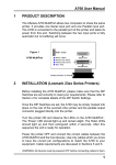
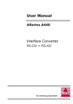
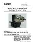
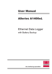
The physical layout of the ASeries A510 is as follows:
Power Jack
Transmit Data (Green)
Data Error (Red)
Power (Yellow)
Serial
Port
Parallel
Port
Receive Data (Green)
DIP Switch
Figure 1 - A510 viewed from both ends and side
2.0 INSTALLATION
Before installing the A510 please make sure that the DIP Switch settings are
according to your requirements. It is most important to set the direction of the
parallel port to either INPUT or OUTPUT as required. The A510 will not operate
unless the direction is set correctly.
Insert the power plug into the power jack socket, next to the Serial connector.
Turn the power ON and observe the LEDs. The Power LED should light up
and remain alight, all other LEDs should light up and then extinguish within 2
seconds. After this sequence the A510 is ready for operation.
Power OFF the A510 and connect the correct cables between the A510 and
the target devices. Use only cables which you know to have the correct pin
configurations to match the A510 to your equipment. Cable requirements and
pin assignments are discussed in Sections 7 and 8.
WARNING:All devices must be powered OFF before connecting cables to
them.
Incorrect cabling may cause damage to either the A510 or your equipment
and is not covered by warranty. If in doubt about pin configurations please
have them checked by your dealer.
1
A510 User Manual
3.0 CHARACTER GENERATION FUNCTION (SELF TEST)
The Character Generation Function in the A510 will output a continuous stream
of printable ASCII characters from either the Serial or Parallel ports. This
function may be used to confidence test both ports of the A510 or to test the
operation of other devices. It is activated in the following manner:
Step 1:
Take note of the original DIP Switch settings of the A510 then turn
the power OFF. Select the output port via the Parallel Port Direction
switch, DIP Switch 1, and set it as required:
Switch 1 is ON
= Output from SERIAL port only
Switch 1 is OFF = Output from both SERIAL & PARALLEL ports
Step 2:
Select the Character Generation Function (Self Test) on the DIP
by setting switch numbers 6, 7 and 8 to Self Test mode as follows:
Note:
Step 3:
',36ZLWFKQXPEHU
6ZLWFK 6HWWLQJ
2Q
2Q
2II
If you are sending the output to the serial port there is another
setting available. Please refer to Table 4-3 in Section 4 for this
alternative setting.
Connect a suitable cable between the A510 and the Output Device.
Power ON the Output Device and then power ON the A510.
The A510 will produce a continuous output as follows:
0123456789:;<=>?@ABCDEFGHIJKLMNOPQRSTUVWXYZ[\]^_abcdefghijklmnopqrstuvwxyz{|}~
0123456789:;<=>?@ABCDEFGHIJKLMNOPQRSTUVWXYZ[\]^_abcdefghijklmnopqrstuvwxyz{|}~
0123456789:;<=>?@ABCDEFGHIJKLMNOPQRSTUVWXYZ[\]^_abcdefghijklmnopqrstuvwxyz{|}~
0123456789:;<=>?@ABCDEFGHIJKLMNOPQRSTUVWXYZ[\]^_abcdefghijklmnopqrstuvwxyz{|}~
0123456789:;<=>?@ABCDEFGHIJKLMNOPQRSTUVWXYZ[\]^_abcdefghijklmnopqrstuvwxyz{|}~
0123456789:;<=>?@ABCDEFGHIJKLMNOPQRSTUVWXYZ[\]^_abcdefghijklmnopqrstuvwxyz{|}~
0123456789:;<=>?@ABCDEFGHIJKLMNOPQRSTUVWXYZ[\]^_abcdefghijklmnopqrstuvwxyz{|}~
0123456789:;<=>?@ABCDEFGHIJKLMNOPQRSTUVWXYZ[\]^_abcdefghijklmnopqrstuvwxyz{|}~
0123456789:;<=>?@ABCDEFGHIJKLMNOPQRSTUVWXYZ[\]^_abcdefghijklmnopqrstuvwxyz{|}~
This output will continue for as long as the A510 is powered ON. To stop
the continuous output simply power OFF the A510.
Step 4:
2
Turn OFF the power to the A510 and re-configure it for normal
use with the DIP Switch settings which you took note of in Step 1.
A510 User Manual
4.0
HARDWARE CONFIGURATION
4.1
How to set the DIP Switch
Before attempting to change the DIP Switch settings, remove the power plug
from the A510. The DIP switches are read only once, when the A510 is powered
ON. They are located at the side of the A510 as shown in Section 1, Figure 1.
4.2
Default Factory DIP Switch Settings
The A510 is factory pre-set to the following configuration:
l
l
l
l
l
l
4.3
Parallel port as OUTPUT
9600 bps
8 Data Bits
No Parity
DTR/DSR Handshaking
1 Stop Bit
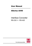
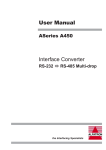
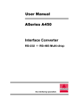
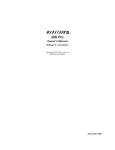
Using and Providing power on the A510 Parallel port
The A510 may be powered directly from pin 18 or alternatively be configured
to power a device connected to its parallel port. This is set via an internal
jumper (J1) on the printed circuit board. To change the setting remove the
cover of the A510, the jumper is located directly beside pin 18 of the Centronics
parallel connector.
(1) A510 may be powered directly from pin 18.
The A510 may be powered through pin 18 by a
regulated input of +5V with a current of 200mA.
When the jumper (J1) is set as per the diagram
shown here, no power is available from pin 18.
Note: This is the factory default setting.
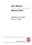
(2) Regulated power supplied by A510 on pin 18.
Set the jumper (J1) to the position shown in the
diagram here to provide 5V DC regulated power
from pin 18 of the parallel connector. This power
is limited to a current of 200mA.
Caution:
If you attempt to draw more than
200mA from pin 18 of the A510, it will
shut itself down.
3
A510 User Manual
4.4
DIP Switch Settings
6ZLWFK
)XQFWLRQ
2))
21
3DUDOOHO3RUW'LUHFWLRQ
2XWSXW
,QSXW
+DQGVKDNLQJ
'75'65
5REXVW
;RQ;RII
Table
4-1
%LWV3HU6HFRQGUHIHUWR7DEOH
'DWD%LWV3DULW\7HVW0RGHUHIHUWR7DEOH
6ZLWFK
.
.
Table
2II
2Q
2II
2Q
2II
2Q
2II
2Q
4-2
2II
2II
2Q
2Q
2II
2II
2Q
2Q
2II
2II
2II
2II
2Q
2Q
2Q
2Q
6ZLWFK
4
'DWD%LWV
3DULW\
6WRS%LWV
6HOI7HVW
2Q
(YHQ
1R
2Q
2II
1RQH
<HV
2Q
2II
2Q
2GG
1R
2Q
2II
2II
1RQH
1R
2II
2Q
2Q
(YHQ
1R
2II
2Q
2II
1RQH
<HV
2II
2II
2Q
2GG
1R
2II
2II
2II
1RQH
1R
2Q
2Q
2Q
Table
4-3
A510 User Manual
5.0
INTERFACE PORT PIN ASSIGNMENTS
5.1
Centronics Parallel Port
Pin Signal
Description
Pin Signal
Description
1
2
3
4
5
6
7
8
9
10
11
12
13
14
15
16
17
18
Active Low
Active High
Active High
Active High
Active High
Active High
Active High
Active High
Active High
Active Low
Active High
Pulled Low
Pulled High
Pulled High
Input & Output
19
20
21
22
23
24
25
26
27
28
29
30
31
32
33
34
35
36
Pulled High
Pulled High
Pulled Low
Note:
Data Strobe
Data Bit 1
Data Bit 2
Data Bit 3
Data Bit 4
Data Bit 5
Data Bit 6
Data Bit 7
Data Bit 8
Acknowledge
Busy
Paper End
Select
Autofeed
Not Connected
Ground
Ground
+5V DC **
(a)
(b)
Ground
Ground
Ground
Ground
Ground
Ground
Ground
Ground
Ground
Ground
Ground
Ground
Initialize
Error
Ground
Not Connected
Not Connected
Select In
Pins are Pulled High to +5V via 4K7 resistor.
Strobe & Data lines are Pulled High to +5V via 1K resistor.
** (1) The A510 may be powered directly from pin 18.
(2) The A510 can supply 200mA +5V DC regulated power from pin 18.
Refer to section 4 for complete details.
5.2
RS-232 Serial Port
The RS-232 Serial Port of the A510 is configuired as DCE.
Pin
Status
Signal
Description
1
2
3
4
5
6
7
8
20
22
Used
Input
Output
Not used - Pulled High
Not used - Pulled High
Output
Used
Not used - Pulled High
Input - Pulled High
Not Used - Pulled High
FG
RD
TD
CTS
RTS
DTR
SG
DCD
DSR
RI
Frame Ground
Receive Data
Transmit Data
Clear To Send
Request To Send
Data Terminal Ready
Signal Ground
Data Carrier Detect
Data Set Ready
Ring Indicator
Note: Pins are pulled high to +9V via 10K resistor.
5
A510 User Manual
6.0 FLOW CONTROL (Handshaking)
6.1
Hardware (DTR/DSR) Handshaking
Hardware, DTR/DSR, handshaking uses the Data Terminal Ready (DTR) and
Data Set Ready (DSR) signal lines to control the flow of data between devices.
This form of handshaking is recommended and is the preferred method of
handshaking under the DOS operating system.
6.2
Software Handshaking - Robust Xon/Xoff
Robust Xon/Xoff handshaking overcomes limitations in the Standard Xon/
Xoff protocol by ensuring that the A510 device repeatedly sends Xon/Xoff
characters to the connected device.
For example, without Robust Xon/Xoff if an Xoff is sent from the A510 to the
connected device and somehow becomes corrupted, the connected device
will not receive the Xoff and will therefore continue to send data to the A510
causing the buffer of the A510 to overflow and resulting in the loss of data.
Robust Xon/Xoff overcomes this situation by sending the Xoff character after
every character received past the cutoff point of the A510 buffer. Also, when
the A510 is receiving data it will send an Xon, every 5 seconds, to the connected
device. The behaviour of the A510 Xon/Xoff flow control buffer is as follows:
l
l
l
An 'Xoff' is issued when there are 35 bytes or less remaining in the
buffer.
An 'Xon' is issued if there are more than 45 bytes available in the
buffer.
The Robust 'Xon' time interval is 5 seconds, this may be observed on
the Transmit Data LED when the A510 is powered on.
7.0 CABLE REQUIREMENTS
Alfatron recommends the use of shielded cable with all of its products. Shielding
reduces EMI Radiation and improves noise immunity. This helps minimise
interference to other equipment and will improve communications reliability.
The recommended cable construction is as follows:
l
l
6
Take the shield (surrounding cable wires) and solder it to the Frame
Ground (FG) pin. If FG is not available, use Signal Ground (SG) but in
this case always use a separate wire for ground which is connected at
both ends.
The shield must be connected at both ends of the cable.
A510 User Manual
8.0
CABLE EXAMPLES
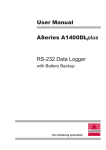
8.1
RS-232 Connection to a PC with a DB-25 Serial Connector
Shield
A510 Cable End
DCE
(DB-25 Male)
8.2
FG
RD
TD
CTS
RTS
DTR
SG
DCD
DSR
1
2
3
4
5
6
7
8
20
1
2
3
4
5
6
7
8
20
FG
TD
RD
RTS
CTS
DSR
SG
DCD
DTR
PC Cable End
DTE
(DB-25 Female)
RS-232 Connection to a PC with a DB-9 Serial Connector
Shield
A510 Cable End
DCE
(DB-25 Male)
8.3
RD
TD
CTS
RTS
DTR
SG
DCD
DSR
3
2
7
8
6
5
1
4
2
3
4
5
6
7
8
20
TD
RD
RTS
CTS
DSR
SG
DCD
DTR
PC Cable End
(DB-9 Female)
RS-232 Connection to other RS-232 Devices
Shield
A510 Cable End
DCE
(DB-25 Male)
FG
RD
TD
CTS
RTS
DTR
SG
DCD
DSR
1
2
3
4
5
6
7
8
20
FG
TD
RD
RTS
CTS
DSR
SG
DCD
DTR
User Device
Cable End
7
A510 User Manual
9.0 SPECIFICATIONS
CPU:
Parallel Port:
Serial Port:
Flow Control Buffer:
LED Indicators:
Power Supply:
Dimensions:
Weight:
Operating Temp:
Storage Temperature:
89C51 Microprocessor
Centronics Parallel
Select as Input or Output
36-pin Centronics female connector
Asynchronous RS-232D
Full duplex communication
DB-25 female connector configured as DCE
DIP Switch Selection:
Baud Rate: 300, 600,1200, 2400, 4800,
(bps) 9600, 19200 and 38400.
Data Bits: 7 or 8
Parity: None, Odd or Even
Stop Bits: 1 or 2
Handshaking: Software (Robust Xon/Xoff)
Hardware (DTR/DSR)
60 byte receive buffer
Power On
Receive Data
Transmit Data
Data Error
(Yellow)
(Green)
(Green)
(Red)
9V (200mA) DC Power Adapter
Fuse & Reverse polarity protection
Plug jack - 5.5mm outer/2.5mm inner diameter
Outer Negative
A510 may be powered directly from pin 18 of the
parallel connector. A regulated 5V DC power supply
with a current of up to 200mA is required.
35mm x 95mm x 110mm
350 grams
10° to 35° C
0° to 45° C
All specifications subject to change without notice
8
N42
DECLARATION OF CONFORMITY
according to the European Commissions EMC Directive 89/336/EEC
We,
of,
Name of Manufacturer:
Address of Manufacturer:
Australian Company Number:
ALFATRON PTY. LTD
UNIT 9, 36 NEW ST.
RINGWOOD VIC 3134
AUSTRALIA
ACN: 005 410 819
declare under sole responsibility that the product:
Product Name:
ASeries RS-232 to Centronics Parallel
Interface Converter
Model Number:
A510
to which this declaration relates is in conformity with the following standards:
CISPR-22 / EN 55022 class B
IEC 801-2 / prEN55024-2
IEC 801-3 / prEN55024-3
IEC 801-4 / prEN55024-4
EMI from Information Technology Equipment (ITE)
Electro Static Discharge Immunity
Radiated RF Immunity
Electrical Fast Transients Immunity