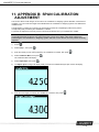
1
LOADRITE™ Force User Manual
LOADRITE™ Force User Manual
Software Number: 60408 Version Number: 2.0
Document Number: MAN-81175-00
Issued Date: July 2011
E: [email protected]
W: www.loadritescales.com
A solution from
www.actronictechnologies.com
© 2011 Actronic Ltd. All rights reserved. Actronic Technologies, Express, Loadrite, Pro, Road Boss and X-Weigh are
trademarks and/or registered trademarks of Actronic Ltd. All other trademarks and registrations are the property of their
respective owners.
The software contains proprietary information of Actronic Ltd; it is provided under a license agreement containing restrictions on
use and disclosure and is also protected by copyright law. Reverse engineering of the software is prohibited.
This document is copyrighted with all rights reserved. Under copyright laws, this document may not be copied in whole or in
part, reproduced in any other media, stored in a retrieval system, or transmitted in any form or by any means, electronic,
mechanical, photocopying, recording or otherwise, without the express written permission of Actronic Ltd. Permitted copies must
carry the same proprietary and copyright notices as were affixed to the original. Under the law, copying includes translation into
another language.
Published in New Zealand.
Disclaimer
Actronic Ltd operates a policy of on-going development. Please note that while every effort has been made to ensure that the
data given in this document is accurate, due to continued product development, the information, figures, illustrations, tables,
specifications, and schematics contained herein are subject to change without notice. Actronic Ltd does not warrant that this
document is error-free. The screenshots and other presentations shown in this manual may differ from the actual screens and
presentations generated by the actual product. All such differences are minor and the actual product will deliver the described
functionality as presented in this document in all material respects. If you find any errors in the document, please report them to
us in writing.
Actronic Ltd assumes no liability in connection with the use of any LOADRITE™ branded product.
This device complies with part 15 of the FCC Rules. Operation is subject to the following two conditions: (1) This device may not
cause harmful interference, and (2) this device must accept any interference received, including interference that may cause
undesired operation.
1-1
LOADRITE™ Force User Manual
1. IMPORTANT SAFETY INFORMATION
PLEASE READ CAREFULLY BEFORE USING THE LOADRITE™ WEIGHING SYSTEM
This is the safety alert symbol. It is used to alert you to potential personal
injury hazards. Obey all safety messages that follow this symbol to avoid
possible injury or death.
WARNING indicates a potentially hazardous situation which, if not
avoided, could result in death or serious injury.
CAUTION indicates a potentially hazardous situation which, if not
avoided, may result in minor or moderate injury.
CAUTION used without the safety alert symbol indicates a potentially
hazardous situation which, if not avoided, may result in property damage.
It is your sole responsibility to place, secure and use the LOADRITE™ Weighing System in a manner that will not
cause accidents, personal injury or property damage. Always observe safe operating practices.
Do not install the LOADRITE™ Weighing System in a way that may interfere with the safe operation of the
vehicle, or deployment of safety equipment.
Before you use the LOADRITE™ Weighing System for the first time, familiarize yourself with the system and its
operation.
Do not handle the LOADRITE™ Weighing System while it is hot. Let the product cool, out of direct sunlight.
Ensure that the LOADRITE™ Weighing System is connected to a power source with the correct fitting and
voltage requirements.
Do not attempt to service the LOADRITE™ Weighing System as this could result in personal injury.
Removing LOADRITE™ Weighing System equipment, adding accessories or modifying your vehicle could affect
the accuracy of weighing data and your warranty.
Failure to adhere to these warnings and cautions may lead to death, serious injury or property
damage. Actronic Ltd disclaims all liability for installation or use of the LOADRITE™ Weighing
System that causes or contributes to death, injury or property damage or that violates any law.
1-2
LOADRITE™ Force User Manual
TABLE OF CONTENTS
1. IMPORTANT SAFETY INFORMATION ...................................................................... 1-2 2. WELCOME .................................................................................................................. 2-5 3. INTRODUCTION.......................................................................................................... 3-6 4. 5. 3.1. LOADRITE™ equipped loader ............................................................................... 3-7 3.2. 3.3. Indicator features ................................................................................................. 3-8 Accurate weighing ................................................................................................ 3-9 THE DAY-TO-DAY WEIGHING PROCESS .............................................................. 4-10 4.1. 4.2. How do I turn on the Indicator? .........................................................................4-10 How do I perform a warm up? ...........................................................................4-10 4.3. 4.4. How do I zero the empty bucket? ......................................................................4-10 How do I weigh and add a bucket load? ...........................................................4-11 4.5. 4.6. How do I finish the load?....................................................................................4-14 How do I put the Indicator into Standby mode? ...............................................4-14 READY SCREEN....................................................................................................... 5-15 5.1. 6. OPERATION MODES................................................................................................ 6-18 6.1. 6.2. 7. The short and long totals ...................................................................................5-16 Target mode ........................................................................................................6-19 Split mode ...........................................................................................................6-20 ADVANCED WEIGHING - TIP-OFF .......................................................................... 7-22 7.1. 7.2. Truck tip-off .........................................................................................................7-22 Stock pile tip-off ..................................................................................................7-23 8. PRINTING .................................................................................................................. 8-24 9. MENU ........................................................................................................................ 9-25 Setup... ................................................................................................................9-26 9.1. 9.2. Auto-Add ..............................................................................................................9-26 9.3. 9.4. Scale # ................................................................................................................9-26 Module ................................................................................................................9-26 9.5. 9.6. Clock ....................................................................................................................9-27 Display .................................................................................................................9-28 9.7. 9.8. Long Total............................................................................................................9-28 Self test ...............................................................................................................9-28 9.9. 9.10. Uplink ..................................................................................................................9-28 Standby ...............................................................................................................9-29 10. APPENDIX A: SYSTEM SPECIFICATIONS ........................................................... 10-30 10.1. 10.2. Weighing accuracy ........................................................................................... 10-30 Minimal weighing delay ................................................................................... 10-30 10.3. Power requirements ........................................................................................ 10-30 1-3
LOADRITE™ Force User Manual
10.4. Physical specifications .................................................................................... 10-30 10.5. 10.6. Environmental specifications.......................................................................... 10-30 Signal inputs and outputs ............................................................................... 10-30 10.7. 10.8. Clock ................................................................................................................. 10-31 Available accessories ...................................................................................... 10-31 10.9. Output/Input connections ............................................................................... 10-31 11. APPENDIX B: SPAN CALIBRATION ADJUSTMENT............................................ 11-33 11.1. Checking the adjustment ................................................................................ 11-34 12. APPENDIX C: ERROR MESSAGES....................................................................... 12-35 12.1. Bouncing load .................................................................................................. 12-35 12.2. Bucket not back ............................................................................................... 12-35 12.3. 12.4. Check power .................................................................................................... 12-35 Check MAG/OPT .............................................................................................. 12-35 12.5. 12.6. Check rotary ..................................................................................................... 12-35 Check scale# ................................................................................................... 12-35 12.7. 12.8. Check tilt .......................................................................................................... 12-35 Check transducer ............................................................................................ 12-36 12.9. 12.10. Check zero ....................................................................................................... 12-36 Lift under range ............................................................................................... 12-36 12.11. 12.12. Need emptying ................................................................................................. 12-36 No lock ............................................................................................................. 12-36 12.13. 12.14. Num Attempts Exceeded ................................................................................. 12-36 Over target ....................................................................................................... 12-36 12.15. 12.16. Overload ........................................................................................................... 12-36 Poor lift ............................................................................................................. 12-36 12.17. 12.18. Printer disabled ............................................................................................... 12-37 Printer error ...................................................................................................... 12-37 12.19. 12.20. Return under range ......................................................................................... 12-37 Speed changed ................................................................................................ 12-37 12.21. Speed too high ................................................................................................. 12-37 12.22. 12.23. Tilt too high ...................................................................................................... 12-37 Too heavy, zero aborted .................................................................................. 12-37 12.24. Warm-up lift...................................................................................................... 12-37 13. APPENDIX C: GLOSSARY ..................................................................................... 13-38 1-4
LOADRITE™ Force User Manual
2. WELCOME
Thank-you for purchasing this LOADRITE™ Weighing System. Please read this manual carefully before using the
Indicator for the first time. Keep this manual in a safe place and use as your first point of reference.
Formatting
The following formatting in this manual identifies specific types of information:
Convention
Type of Information
Bold
Indicates a button on the Indicator, or
Indicates an area displayed on-screen, including buttons, headings,
field names and options.
Indicates the name of a screen or window, or
Indicates an operation mode that the Indicator can be set to.
Italics
Monospace
The exact error message displayed on-screen.
Action Terms
The following terms are used throughout this manual to describe actions:
Term
Description
Press
Push and release a button quickly.
Press and hold
Push and hold a button for 2-3 seconds.
Select
Use the arrow buttons to "highlight" an item in a menu or list.
2-5
LOADRITE™ Force User Manual
3. INTRODUCTION
The LOADRITE™ weighing system measures the weight of loads lifted by wheel loaders, forklift trucks and
similar machines that use hydraulic rams to lift the load. The main parts of the LOADRITE™ Weighing System
are:
the Indicator installed in the cab of the loader, and
the connected sensors installed on the lifting arms.
As a load is lifted, the trigger and hydraulic pressure transducers send information to the LOADRITE™ Indicator.
This information is converted into a digital weight reading which is displayed on the LOADRITE™ Indicator.
The LOADRITE™ Weighing System can add each lifted load to running totals so that Trucks are loaded
accurately and daily productivity levels can be tracked.
The LOADRITE™ Indicator is the main user interface with the LOADRITE™ Weighing System.
3-6
LOADRITE™ Force User Manual
3.1. LOADRITE™ EQUIPPED LOADER
Item
Description
Inclinometer (optional; required for Legal for Trade application)
Printer (optional)
Remote Add Button (optional)
LOADRITE™ Indicator
Interlock Switch (optional; required for Legal for Trade application)
Trigger
Pressure Transducer
3-7
LOADRITE™ Force User Manual
3.2. INDICATOR FEATURES
Icon
Name
Description
Trigger Light
Illuminates when a load is lifted past the trigger point. When this light is on,
the load may be added.
Menu
Displays the Menu.
Exit
Moves back one menu screen.
Cancel
Cancels changes.
Standby Mode
Press and hold for 5 seconds to enter Standby mode.
Split Mode
Activates Split mode weighing.
Down
Moves down a list of options.
Target Mode
Activates Target mode weighing.
Up
Moves up a list of options.
Tip-Off
Activates Tip-off weighing.
Selects an item.
Accepts changes.
Recall
Recalls the last load.
Subtract
Subtracts the current load from the total.
Left
Scrolls up through values.
Moves the cursor right, or
Scrolls down through values.
Adds the current bucket load to the total.
Turn Auto-Add on or off.
Enter
Right
Add
3-8
Clear
Clears the short total for the current product.
Zero Bucket
Zeroes the empty bucket.
LOADRITE™ Force User Manual
3.3. ACCURATE WEIGHING
For maximum accuracy, ensure that:
Check Zero is performed regularly.
Load lifting motion is steady and smooth, with no acceleration or bounce.
The bucket is fully rolled back during the lift.
The loader is on level ground.
3.3.1. Obtaining the Best Weighing Results
Lifting speed
For best results, operate the lift lever before accelerating the engine so that the machine does not rock as it lifts,
i.e. use normal revs.
Trigger point
Start the lift well below the trigger point. This ensures that all acceleration and load bounce has been eliminated
well before the weighing sequence begins.
Note: We recommend that there are at least two seconds of lift before the trigger point.
Bounce
Most loaders have pneumatic tires which can cause the machine to bounce when lifting.
To minimize the effect of bounce, always operate the lift lever before accelerating the engine and start the lift well
below the trigger point.
Center of gravity
The hydraulic pressure in the lifting cylinders depends on where the center of gravity of the load is. It is important
that the bucket is always in the same position: fully rolled back.
3.3.2. Legal for Trade Systems
LOADRITE™ systems meet Legal for Trade requirements in certain countries. This enables
material to be weighed and sold directly from the loader.
For more information or to enquire if Legal for Trade is available in your country, contact your
LOADRITE™ distributor.
Tip: Operating requirements for Legal for Trade systems are detailed in this User Manual where they differ from
standard operating requirements.
3-9
LOADRITE™ Force User Manual
4. THE DAY-TO-DAY WEIGHING PROCESS
The following is the basic process for day-to-day weighing with the LOADRITE™ Weighing System:
1)
Turn on the Indicator.
2)
Perform a warm-up.
3)
Zero the empty bucket.
4)
Weigh and add each load.
5)
When you have finished loading the truck, clear the short total.
6)
When you have finished using the LOADRITE™ Weighing System, put the Indicator into Standby mode.
4.1. HOW DO I TURN ON THE INDICATOR?
The LOADRITE™ Indicator will turn on automatically when you start the loader.
4.2. HOW DO I PERFORM A WARM UP?
For best weighing accuracy, the hydraulic fluid in the lift cylinders should be at normal operating temperature. This
is achieved by raising and lowering the empty bucket.
The above message will display if the Indicator has been turned off for more than one hour. If you see the above
message, you need to raise and then lower the empty bucket past the trigger point three times:
1)
Raise the bucket past the trigger point.
2)
Lower the bucket past the trigger point.
3)
Repeat two more times until the message disappears.
When the warm up has completed, the Ready screen will display.
4.3. HOW DO I ZERO THE EMPTY BUCKET?
The Check Zero functionality is only available if selected at installation.
It is necessary to periodically "zero" the LOADRITE™ Weighing System because small errors can occur due to a
build-up of material in the bucket.
If you see the above message, you need to zero the empty bucket. The message will display:
Every 15 minutes for the first hour, and
Every 30 minutes thereafter (the default period is 30 minutes, but it may be set between 15-180 minutes).
Complete the following to zero the bucket:
IMPORTANT: When weighing a load, the loader must be level, and the bucket must be empty and kept fullyrolled back.
1)
Ensure that the loader is level and the bucket is empty.
2)
Raise the empty bucket.
3)
Press
.
The Zero Complete message will display, before the Ready screen is displayed.
4-10
LOADRITE™ Force User Manual
4.4. HOW DO I WEIGH AND ADD A BUCKET LOAD?
When the Ready screen is displayed, bucket loads can be weighed.
IMPORTANT: When weighing a load, the loader must be level with the bucket kept fully-rolled back.
1)
Raise the bucket load smoothly past the trigger point using constant engine revs.
The Weighing message will display.
2)
(Trigger light) will illuminate and the weight of the current load, the short total
The Indicator will beep,
and the potential new weight will display.
3)
Press
to add the load.
A message will display the number of buckets added to the current load, for example Bucket Add #1.
is not pressed within 8 seconds of the load being lifted past the trigger point, the Indicator will
Note: If
beep and the Time Out message will display. The weight will then be discarded and the Ready screen will
display. The number of seconds before the Indicator times out may differ, depending on how it was set during
installation.
When the load has been added, the Ready screen will display with the new short total and the number of
bucket loads.
4-11
LOADRITE™ Force User Manual
4.4.1. Auto-Add
The Auto-Add functionality is only available if selected at installation. Some features may not
available, depending on your model of LOADRITE™ Weighing System.
The LOADRITE™ Weighing System can be set to automatically add a bucket load when lifted past a trigger point
for a specified number of seconds OR when the bucket is rotated forward to tip off the load. This means that you
don't have to press
after lifting each load.
Depending on installation setup:
Bucket loads may not be added if under a specified amount
Auto-Add may be turned on or off via the Setup Menu or by pressing
.
4.4.1.1. Auto-Add toggle
You can toggle between using Auto-add and using the normal add process from the Total screen.
Turn Auto-Add on
1)
From the Ready screen, press
.
The Auto-Add On? message will display.
2)
Press
.
The message will change to Auto-Add On and the Total screen will display.
Turn Auto-Add off
1)
From the Ready screen, press
.
The Auto-Add Off? message will display.
2)
Press
.
The message will change to Auto-Add Off and the Ready screen will display.
4.4.2. Remote Add button
The LOADRITE™ Weighing System has an optional Remote Add button which is normally mounted
near the lift lever. If the Remote Add button is installed in your loader you can use it interchangeably
with the
4-12
button on the Indicator.
LOADRITE™ Force User Manual
4.4.3. Subtract a bucket load
This function can be useful when only part of a final load of loose material is required. Weigh and add a full load,
then tip the amount required into the truck. Then re-weigh and subtract the amount remaining by completing the
following:
IMPORTANT: When weighing a load, the loader must be level with the bucket kept fully-rolled back.
1)
Raise the load smoothly past the trigger point.
2)
The Indicator will beep,
(Trigger light) will illuminate and the weight of the current load, the short total
and the potential new weight will display.
3)
Press
.
The Bucket Subtract message will display. The amount will be subtracted from the short total. The Ready
screen will display.
4.4.4. Recall a bucket load
The Recall function is equivalent to lifting the same load again and can be used to correct mistakes. The last load
can be recalled if it has been added or subtracted.
To recall a previously lifted weight, complete the following:
1)
.
Press
The last weight lifted will be displayed.
2)
Complete the following:
If...
Then...
the last action was an "add"
press
.
The bucket load is subtracted from the short total and long total.
the last action was a "subtract"
press
.
The bucket load is added to the short total and long total.
4-13
LOADRITE™ Force User Manual
4.5. HOW DO I FINISH THE LOAD?
When you have finished adding loads to the truck, you must clear the short total. For example, you need to clear
the short total when you have finished loading a truck.
To clear the short total, complete the following:
Press and hold
.
The short total will display briefly, followed by the Total Cleared message, then the Ready screen.
For more information on the short total, see, see "The short and long totals" on page 5-16.
4.6. HOW DO I PUT THE INDICATOR INTO STANDBY
MODE?
If you are not going to use the LOADRITE™ Weighing System for a while, you can put the Indicator into Standby
mode by completing the following:
Option 1
Press and hold
for 5 seconds.
The Indicator will enter Standby mode.
Option 2
1)
Press
2)
or
to scroll up or down until Standby is selected, then press
Press
The Indicator will enter Standby mode.
.
.
Option 3
The LOADRITE™ Indicator will automatically go into Standby mode if it is not used for two hours.
How do I exit Standby mode?
Press any button to exit Standby mode.
Either the Login screen or Ready screen will display.
4-14
LOADRITE™ Force User Manual
5. READY SCREEN
The Ready screen is the first screen that you will see when you turn on the Indicator. It displays the short total,
number of bucket loads and other information.
Component
Description
Short total
The current short total of product loaded.
Clock
The current time.
Weighing implement
The weighing implement being used by the loader.
Auto-add
Indicates that the Auto-add functionality is On.
Unit of weight
The unit of weight being used. The Short total is displayed in this unit of
weight.
5-15
LOADRITE™ Force User Manual
5.1. THE SHORT AND LONG TOTALS
The LOADRITE™ Weighing System keeps a running total of the load weights. For each product, two independent
totals are stored - the short total and the long total.
Term
Definition
The running total amount of product weighed and loaded onto a truck or carriage.
The Short Total amount is displayed on the Ready screen and will continue to accumulate
Short Total
until it is cleared by pressing
Long Total
.
The total amount of product loaded over a long period, such as a work shift or day.
5.1.1. Clear the short total
The short total keeps accumulating until it is cleared. Clear the short total after a load has been completed, for
example, after each truck or carriage load.
.
Press
The short total will display briefly, followed by the Total Cleared message, then the Ready screen.
Note: If the LOADRITE™ Weighing System has a printer connected, then depending on your installation settings,
(i) the totals may be printed before being cleared, or (ii) you may be prompted to print the totals after the Total
Cleared message is displayed.
5.1.2. View and clear the long total
You can view the long total for the current product at any time.
1)
Ensure the Ready screen is displayed, then press
2)
Press
3)
Press
.
The long total will display, followed by the number of
buckets added.
or
.
to scroll up or down until Long Total is selected.
After a few seconds, the Indicator will display the Ready screen.
Clear the long total
1)
Ensure the Ready screen is displayed, then press
2)
Press
3)
Press
.
The long total for the current product is displayed along with the number of buckets added.
5-16
or
.
to scroll up or down until Long Total is selected.
LOADRITE™ Force User Manual
4)
Press
.
The Long Total Clear? message will display.
5)
Press
again to clear the long total.
The Long Total Cleared message will display. If the LOADRITE™ Weighing System has a printer
connected, the total will be printed.
to cancel the clearing of the long total.
Press
The Clear Aborted message will display.
Note: If no button is pressed, the clear command will be automatically cancelled.
5-17
LOADRITE™ Force User Manual
6. OPERATION MODES
The operation modes that are available depend on the modes selected at installation.
The LOADRITE™ Indicator can be operated in different modes:
Mode
Description
Total
This is the normal mode of operation. As loads are added, the weights
are added to the totals. The short total is displayed.
Target
In this mode, a target weight is entered into the Indicator before loading.
As loads are added, the remaining value to reach the target is displayed.
Split
The mode used when loading a multiple train wagons or a truck with
multiple trailers where individual totals are required for each individual
vehicle. Can be used within Total or Target modes.
6-18
LOADRITE™ Force User Manual
6.1. TARGET MODE
Target mode is only available if selected at installation.
Target mode is typically used when loading a truck to its optimum payload. This feature provides an easy way to
load up to a target weight for a product in a series of lifts. In Target mode, the Indicator displays the to load (or
target) value, which is the remaining amount to reach the target.
Before loading, the operator enters a target weight. Each time a weight is added, the to load value is reduced by
that weight.
6.1.1. How do I enter Target mode and input a new target?
1)
Press
2)
Press
to clear the previous totals.
.
When the Target? 0.00 message is displayed, use
and
to enter the new target amount.
3)
Press
.
The Target Updated message will display briefly, then the To Load screen will be displayed.
4)
Lift a bucketload.
As you lift a bucketload, the target weight is displayed along with the current lifted weight and the potential
weight if the lift is loaded.
5)
Press
to add the bucketload.
As the truck is loaded, the target amount will decrease.
The aim is to get as close to 0 (zero) as possible. A positive to load value is under the target, a negative to load
value is over the target.
6-19
LOADRITE™ Force User Manual
6.1.2. How do I reset the target?
When the load is complete, the target must be reset. This is the equivalent of clearing the short total in Total
mode.
.
To reset the target, press
The Target Reset message will display briefly and then the Target screen will display.
6.1.3. How do I return to Total mode?
To return to Total mode from Target mode, the target must be set to 0.
1)
Press
2)
When the Target? 0.00 message is displayed, press
The Ready screen will display.
.
, then press
.
6.2. SPLIT MODE
Split mode splits the total weight into multiple sub-totals, providing an easy way to load train wagons, or a truck
and trailer. Split mode is also used to track load distribution over a single vehicle unit, to avoid overloading an
axle.
Split mode can be used in conjunction with Total or Target modes.
Example
A truck with a trailer requires loading. The truck can carry 10,000 tonnes and the trailer 15,000 tonnes, making a
total of 25,000 tonnes.
6.2.1. Split mode within Total mode
1)
In Total mode, load the truck with the required amount or product.
2)
When the required amount of product for the truck is reached, press
.
The subtotal will briefly display, then the Split screen will display. The grand total of the entire vehicle is
shown along with the short total for the trailer.
3)
Add the required amount of product to the trailer.
The grand total will update along with the total number of buckets.
6-20
LOADRITE™ Force User Manual
4)
If you would like to split the load to another trailer, press
5)
When all trailers have been filled, press
, then go to step 3. Otherwise, continue to step 5.
to clear the totals.
6.2.2. Split mode within Target mode
1)
In Target mode, enter the target weight for the truck.
2)
Load the truck with the required amount of product.
3)
When the required amount of product for the truck is reached, press
4)
Press
5)
When the Target? message is displayed, use the keypad to enter a target weight for the trailer.
The Split screen will display showing the current target weight for the trailer and the grand total for the entire
vehicle.
6)
Add the required amount of product to the trailer.
7)
Press
to clear the totals.
The Ready screen will display.
.
.
6-21
LOADRITE™ Force User Manual
7. ADVANCED WEIGHING - TIP-OFF
The Tip-off functionality is only available if selected at installation.
Tip-off weighing is the adjustment of the final load. It is possible to tip a measured amount of the product out of
the last bucket to ensure an exact target weight is reached, where the final load would otherwise exceed the
truck's capacity. There are two different methods, depending on the way your LOADRITE™ Weighing System has
been configured:
Truck tip-off (default)
Stock pile tip-off
Tip-off is only available in Total and Target modes.
7.1. TRUCK TIP-OFF
Using this method, the operator tips a measured amount of product from the bucket into the truck and dumps the
rest.
1)
Lift the load in the normal way.
The Indicator will display the lifted weight.
2)
.
Lift the bucket to a suitable height over the truck, then press
The Tip-Off Wait message will display briefly. Then the screen will display two figures, the amount in the
bucket and the short total.
3)
Roll the bucket partially forward, tipping product into the truck. The Indicator will give a live weight as it is
tipped into the truck.
IMPORTANT: Do not raise or lower the lifting arms when tipping, as this will adversely affect the live weight
reading. The bucket needs to be rolled back for an accurate weight.
4)
When the required truck load weight is reached, press
.
Note: You cannot add a weight while the Wait... message is displayed.
5)
Move the bucket away from the truck and dump any remaining product.
7-22
LOADRITE™ Force User Manual
7.2. STOCK PILE TIP-OFF
Using this method, the operator dumps product from the bucket until it contains the right amount for loading onto
the truck.
1)
Lift the load in the normal way.
The Indicator will display the lifted weight.
2)
Press
.
The Tip-Off Wait message will display briefly. Then the screen will display the amount in the bucket and the
short total.
3)
Roll the bucket partially forward, dumping the product.
The Indicator will display the weight in the bucket and the potential weight of the truck.
Note: Do not raise or lower the lifting arms when tipping, as this will adversely affect the live weight reading.
The bucket needs to be rolled back for an accurate weight.
4)
Keep dumping the product until the desired weight has been reached, then press
.
Note: You cannot add a weight while the Wait... message is displayed.
5)
Tip the product from the bucket into the truck.
7-23
LOADRITE™ Force User Manual
8. PRINTING
Depending on your configuration, various weight data is printed either:
when
when
is pressed at the end of a load, or
,
,
or
is pressed.
The information that is printed depends on settings selected at installation. For further information, contact your
LOADRITE™ distributor.
8-24
LOADRITE™ Force User Manual
9. MENU
The Menu options that are available depend on options selected at installation.
The Menu provides options for configuring the LOADRITE™ Weighing System.
To display the Menu, press
option.
To exit the Menu, press
Menu Option
Setup…
twice. Press
or
to scroll up or down, then press
to select an
.
Description
Displays the Install Menu.
For further information, contact your LOADRITE™ distributor.
Auto-Add
Select whether or not Auto-Add is enabled.
Language
Select the language for the Indicator.
Scale#
Select the scale.
Module
Displays the Data Module screen.
Clock
Displays the Clock screen.
Display
Select the screen backlight and contrast.
Long Tot
Displays the Long Total screen.
Self Test
Runs a system self test
Uplink
Allows the Indicator to communicate with the LOADRITE™Toolbox PC software
Standby
Puts the Indicator into Standby mode
9-25
LOADRITE™ Force User Manual
9.1. SETUP...
The Setup Menu provides options for configuring the LOADRITE™ Indicator at installation. A security code is
required to access this menu.
For further information, contact your LOADRITE™ distributor.
9.2. AUTO-ADD
Controls whether or not the Auto-Add functionality is enabled.
Select either On or Off, then press
.
9.3. SCALE #
The Scale options are only available if Multiple Scales functionality has been enabled during
installation.
This option enables the use of different load bearing implements (for example, bucket or forks) on the loader. The
operator needs to select the correct scale for the attached implement.
Tip: You should perform a Check Zero after changing the implement.
9.4. MODULE
The Module option is only available if a LOADRITE™ Data Module is connected to the Indicator
and Data Logger functionality has been correctly configured during installation.
The Data Module Menu provides functionality for use with LOADRITE™ Data Modules.
The following menu items are available:
Option
Description
Property
Lists the properties of the Data Module.
Backup
Saves the product list and data lists to the Data Module.
Restore
Uploads data stored on the Data Module to the LOADRITE™ Indicator. This can be used to
share data between Indicators.
9-26
LOADRITE™ Force User Manual
9.5. CLOCK
Controls the time and date on the Indicator.
9.5.1. Setting the time
1)
From the Clock Menu select Time, then press
.
The time will display with the cursor over the first digit.
2)
Use the keypad to enter the time.
3)
Press
or
4)
Press
to confirm the new time.
to select AM or PM.
9.5.2. Setting the date
1)
From the Clock Menu select Date, then press
2)
Use the keypad to enter the month and day.
3)
Press 1-9 for January to September; Press 0 then 0 for October; Press 0 then 1 for November; Press 0
then 2 for December.
4)
Press
.
to confirm the new date.
9.5.3. Setting the year
1)
From the Clock Menu select Year, then press
2)
Use the keypad to enter the last two digits of the year. For example, press 1 then 1 for 2011.
3)
Press
.
to confirm the new year.
9-27
LOADRITE™ Force User Manual
9.6. DISPLAY
This option allows the display to be configured. The following menu items are available:
9.6.1. Changing the screen brightness
To change the brightness of the display screen, complete the following:
1)
From the Display Menu select Light, then press
2)
Press
or
3)
Press
to save the brightness level.
.
to adjust the backlight brightness up or down.
9.6.2. Changing the screen contrast
To change the contrast of the display screen, complete the following:
1)
From the Display Menu select Contrast, then press
2)
Press
or
3)
Press
to save the contrast level.
.
to adjust the backlight contrast up or down.
9.7. LONG TOTAL
View and clear the long total for current products.
See View and clear the long total, (see "View and clear the long total" on page 5-16).
9.8. SELF TEST
This function tests various functions and the internal memory. All tests are run automatically when this option is
selected. When the test has completed, the Ready screen will display.
9.9. UPLINK
This option is used to upload a configuration file created using LOADRITE™ Toolbox via a LOADRITE™ Data
Module or from a PC via a EDP cable. The configuration file contains product names, data lists and settings.
For information on creating a configuration file, refer to the LOADRITE™ Toolbox User Manual.
9.9.1. Uploading a configuration file via a EDP cable
1)
From the Uplink Menu select EDP, then press
2)
When the Upload Data? message displays, press
3)
When the Clear Data? message displays, press
9-28
.
.
.
LOADRITE™ Force User Manual
9.9.2. Uploading a configuration file via a LOADRITE™ Data Module
1)
From the Uplink Menu select LD940, then press
2)
Connect the LOADRITE™ Data Module to the Indicator.
3)
When the Upload Data? message displays, press
4)
When the Clear Data? message displays, press
.
.
.
9.10.STANDBY
This option puts the Indicator into Standby mode. The Indicator will also go into Standby mode if it is not used for
two hours.
Press any button to exit Standby mode.
9-29
LOADRITE™ Force User Manual
10. APPENDIX A: SYSTEM SPECIFICATIONS
10.1.WEIGHING ACCURACY
Typical accuracy is within 1% for most bucket loaders. This may vary with different machine types, installation
options, and the operating environment.
10.2.MINIMAL WEIGHING DELAY
Weighing delay is minimal, because the weighing function is carried out during a normal lift.
10.3.POWER REQUIREMENTS
Supply voltage
12 to 32V DC
Supply current
LOADRITE™ Indicator: 160mA typical, 350mA max.
LOADRITE™ printer: 50mA standby, 4A peak.
Automatic transient suppression. Exceeds relevant SAE specifications for DC automotive power supply
transients.
10.4.PHYSICAL SPECIFICATIONS
LCD display
Backlit.
Tactile keypad
Backlit. Numeric and special functions.
Weight
1.5 kg (3.2lb)
Dimensions
W145 x L240 x D110mm
(5.7 x 9.4 x 4.3 in)
10.5.ENVIRONMENTAL SPECIFICATIONS
Operating temperature
-10°C to 50°C (14°F to 122°F)
Storage temperature
-50°C to 100°C (-58°F to 212°F)
Indicator
Protected to IP54.
Pressure transducer
Protected to IP69.
The Indicator wear-out mechanisms have been evaluated and improved through several iterations of cyclic
thermal stress between -90°C and +110°C with simultaneous 6-axis random, repetitive shock exceeding 50Grms.
10.6.SIGNAL INPUTS AND OUTPUTS
Pressure transducer
input
4 - 20mA (0-100%)
Trigger 1: Magnetic or Optical. Pull-up resistor with switch to ground.
Trigger
Trigger 2: Rotary. Pulse width modulated 0-5V.
Serial communications
10-30
RS232C protocol to printer and LOADRITE™ Data Module.
LOADRITE™ Force User Manual
10.7.CLOCK
Built-in clock
Hours, minutes, day, month, year.
10.8.AVAILABLE ACCESSORIES
LOADRITE™ printer
Dot matrix, 24 character columns.
Data Module
Provides electronic data collection.
Remote add button
For operator convenience.
Interlock system
To disable weighing under defined machine conditions.
A number of additional operating features can be enabled at the time of installation.
10.9.OUTPUT/INPUT CONNECTIONS
Connection
Power / Control
Printer / Data Logger
Pressure Transducer
10-31
LOADRITE™ Force User Manual
10.9.1.
Power / Control
1. Negative supply (ground)
2. Positive supply
3. Remote button 2 (clear)
4. Remote button 1 (add)
5. Tilt sensor 1
6. Tilt sensor 3
7. Tilt sensor 2
8. +VAUX
9. Digital out
10. Boom position
11. Stick position
12. CAN hi
13. CAN lo
14. +V raw
15. Ground output
10.9.2.
Printer / Data Logger
1. Negative supply to printer
2. Positive supply to printer
3. +VAUX
4. RX2
5. TX2
6. Printer RS232 output
7. Printer busy input
8. LOADRITE™ Data Module RS232 input
9. LOADRITE™ Data Module RS232 output
10. Ground output
11. Boot
12. N.C.
10.9.3.
Pressure Transducer
1. +VAUX
2. Return pressure input
3. Transducer current input
4. +VAUX
5. Lift pressure input
6. Shield
7. Ground
10-32
LOADRITE™ Force User Manual
11. APPENDIX B: SPAN CALIBRATION
ADJUSTMENT
This function allows small changes to be made to the LOADRITE™ Weighing System calibration if the bucket is
modified, or if no accurate test weight was available when the LOADRITE™ Weighing System was calibrated at
installation time.
The adjustment is carried out by entering the total weight recorded at a weighbridge (scale house) and the
corresponding total provided by the LOADRITE™ Indicator.
To perform the adjustment a security access code must be obtained from your LOADRITE™ installer.
WARNING The LOADRITE™ Weighing System alters its calibration every time this function is used. It
is important that this function is only used once with a given set of data. If the same weights are
entered again, the LOADRITE™ Weighing System will over-correct and its accuracy will be seriously
impaired.
1)
Press
2)
Select Setup..., then press
3)
Enter the security access code provided by the LOADRITE™ installer, then press
4)
Select Calibration Menu, then press
The Calibration Menu will display.
5)
Select Adjust Span, then press
6)
The Adjust Span message will display briefly and then the LOADRITE Adjust Span screen will display.
7)
Enter the total weight provided by the LOADRITE™ Indicator, then press
.
.
.
.
.
.
11-33
LOADRITE™ Force User Manual
8)
Enter the total weight provided by the weighbridge, then press
9)
The LOADRITE™ Indicator briefly displays the Calibration Updated message, and then returns to the
Calibration Menu.
.
11.1.CHECKING THE ADJUSTMENT
The Calibration Adjustment can be checked by obtaining and comparing new LOADRITE™ and weighbridge
values. If necessary, the Calibration Adjustment can be performed again using the new data.
IMPORTANT: All trucks and trailers should have tare weights confirmed for all loads to be checked. This ensures
that a true weight can be established. Avoid split-weighing the truck and trailer.
11-34
LOADRITE™ Force User Manual
12. APPENDIX C: ERROR MESSAGES
Error messages may be displayed for a variety of reasons which are detailed below.
12.1.BOUNCING LOAD
If the lift arms are bouncing significantly while weighing, an error occurs. This can happen if, for example, the
loader is driven over uneven ground while lifting the load.
Depending on the installation of the particular LOADRITE™ Weighing System, there are two possibilities:
No weight is displayed and therefore there is no weight to add. Repeat the lift.
Weighing Error is turned off and a weight is displayed. Add the weight to the total (bearing in mind that the
weight measurement is not reliable) or ignore this weight and repeat the lift smoothly.
12.2.BUCKET NOT BACK
The bucket must be crowed fully back for each lift. The Bucket not back message will be displayed if the
LOADRITE™ Weighing System has not detected that the bucket is fully crowded back.
Note: This message should only be displayed when using a Legal for Trade scale.
12.3.CHECK POWER
The power supply has reached an unstable level. Check that the power source is stable and between +12V and
+32V.
12.4.CHECK MAG/OPT
There is a fault in the magnetic or optical trigger or the cable that connects the trigger. If using an optical trigger,
check that the lens is clear and dust-free.
12.5.CHECK ROTARY
There is a fault in the rotary trigger or the cable that connects the trigger. Check that the trigger is still securely
mounted and that the trigger finger has not been damaged.
12.6.CHECK SCALE#
This message displays when
is pressed if the Indicator is set up for use with multiple scales.
If the weight is greater than 10% of full bucket capacity for the selected scale, the screen displays Check Scale#
message. The operator needs to ensure the correct scale is selected for the attached implement, as implements
differ considerably in weight.
12.7.CHECK TILT
There is a fault in the tilt sensor used for ground slope compensation or the cable that connects the sensor.
Check that the tilt sensor is still securely mounted and that the cable has not been damaged.
12-35
LOADRITE™ Force User Manual
12.8.CHECK TRANSDUCER
There is an error in the pressure transducer signal input. This indicates a fault in either the pressure transducer or
the cable that connects the transducer.
12.9.CHECK ZERO
The operator is automatically reminded to check zero.
12.10.
LIFT UNDER RANGE
The lift pressure was too low. This indicates a fault in either the pressure transducer or the cable that connects
the transducer.
12.11.
NEED EMPTYING
The bucket must be crowed fully forward to ensure that all material has been emptied. The Need Emptying
message will be displayed If the LOADRITE™ Weighing System has not detected that the bucket has been
crowded fully forward.
Note: This message should only be displayed when using a Legal for Trade scale.
12.12.
NO LOCK
The interlock was not closed when lifting the load. The interlock must be closed (or the bucket must be fully rolled
back) while lifting the load. No weight is displayed and therefore there is no weight to add.
12.13.
NUM ATTEMPTS EXCEEDED
This message displays if the number of attempts to perform a check zero is exceeded when FACT is activated.
The number of attempts is set during installation.
12.14.
OVER TARGET
Adding the lifted weight will exceed the target value. The lifted weight can still be added by pressing
.
Note: The Auto-add function will not automatically add over-target weight.
12.15.
OVERLOAD
The lifted weight exceeds the full scale (capacity) setting. If the Overload Error is set during installation,
overloaded weight cannot be added.
12.16.
POOR LIFT
If a weighing error is close to, but not greater than, the tolerance limit, the LOADRITE™ Indicator displays this
warning message. The weight can be added as usual.
12-36
LOADRITE™ Force User Manual
12.17.
PRINTER DISABLED
Print function has been disabled at installation.
12.18.
PRINTER ERROR
There is a fault in the printer. Check that the printer is online and has paper.
12.19.
RETURN UNDER RANGE
The return pressure was too low. This indicates a fault in either the pressure transducer or the cable that connects
the transducer.
12.20.
SPEED CHANGED
For accurate measurement, the speed of raising the lift arms must be smooth, without acceleration or
deceleration. The LOADRITE™ weighing system can detect changing speed as the arms go past the trigger
point. Depending on the installation of the LOADRITE™ Weighing System, there are two possibilities:
No weight is displayed, and therefore there is no weight to add. Repeat the lift and avoid accelerating and
decelerating at or near the trigger sequence.
A weight is displayed. Add weight to the total (bearing in mind that the weight measurement is not reliable) or
ignore this weight and repeat the lift smoothly.
12.21.
SPEED TOO HIGH
This message displays if the speed of raising the arms is too fast and exceeds predefined limits.
Lift the arms again slower. If the Speed Too High message displays again, there may be a fault in the system.
The LOADRITE™ Weighing System should be checked and, if necessary, re-calibrated.
12.22.
TILT TOO HIGH
The angle of the loader is at an unsafe roll or pitch while weighing. The Tilt Too High message accompanies the
specific roll or pitch error at the top bar of the display.
12.23.
TOO HEAVY, ZERO ABORTED
If the weight of material in the bucket is greater than 10% of full bucket capacity when
is pressed, the
screen displays this message and does not alter any settings. This prevents any accidental zeroing of valid
weights.
Note: If the bucket is empty and the message still occurs, there may be a fault in the system. The LOADRITE™
Weighing System should be checked and, if necessary, re-calibrated.
12.24.
WARM-UP LIFT
This message displays if the LOADRITE™ Indicator has been turned off for more than one hour, prompting a
warm-up lift.
12-37
LOADRITE™ Force User Manual
13. APPENDIX C: GLOSSARY
A
Auto-add
Interlock
Automatically adds the lifted weight to the total weight
every time a load is lifted.
Sensors which detect the back and forward positions of the
bucket. Can be used in Legal for Trade software, where the
bucket must be fully rolled back for weighing and rolled
forward for emptying.
B
Bucket
The attachment on the loader that holds the bulk material
or load while it is being transferred.
C
Check Zero
The message displayed periodically to remind the operator
to use the Zero function to set the weight of the bucket to 0.
See also Zero/Zeroing.
D
See also Legal For Trade.
L
Legal for Trade
Certification by a local weights and measures authority to
legally sell product from your loader or other scale.
Load
The amount of product added to a truck, or the act of
adding product to a truck.
Loader
Data Module
A memory device which connects to the Indicator to store
payload and related data. The Data Module can then be
connected to a PC running MMS software to transfer the
data for the creation of productivity reports.
The heavy equipment machine or vehicle that is primarily
used to load product onto a vehicle such as a truck,
hopper, rail-car, etc.
May also be known as a front-end loader, loading
machine, loading vehicle, wheel loader, etc.
Display
LOADRITE™ Weighing System
A screen with adjustable backlighting for night and low-light
operations. Used to display weight information and
messages.
Refers to the entire LOADRITE™ hardware and software
weighing system installed at a site, including the Indicator,
transducers, sensors, modem, MMS software, etc.
Docket
A printed record of a load.
May also be known as Ticket.
May also be referred to as LOADRITE™ System.
Long Total
The total amount of product loaded over a long period,
such as a shift or day.
I
Indicator
M
The LOADRITE™ user interface installed in a loader which
the operator uses to record bucket weights. When used
with a belt scale, the term Integrator should be used.
Modem
Note: May also be known as Console, Module, In-Cab
Console, Loadrite, Loadrite Console, Head Unit, Clock,
Computer, Scale; however Indicator is the preferred term.
A device used to transfer live payload and other data from
the Indicator to a PC with MMS installed. There are two
classes of modem:
13-38
See also Short Total.
Cellular model, for example LD311
Radio modem, for example LD100.
See also Cellular Modem and Radio Modem.
LOADRITE™ Force User Manual
O
T
Operation Mode
Target Mode
Any mode that relates to the running total of accumulated
weights, for example, Total or Target mode.
A mode used to enter a predetermined product target
weight. The Indicator will calculate and display the amount
of product required to reach the target. For each lift, the lift
weight will be subtracted from the displayed amount until
the target weight is reached.
Operator
The person operating the loader.
See also Operation Mode.
Also known as Loader Driver or Loader Operator.
Ticket
P
A printed record of a load.
Pressure Transducer
A pressure sensor connected to the loader’s hydraulic
system in order to measure the hydraulic pressure required
to lift a load.
Tip-off
Printer
An optional accessory mounted in the loader cab. It
provides a paper record of the weighing information
collected by the Indicator.
See also Docket or Ticket.
Product
Material that comprises a load. For example, salt, coal, etc.
R
May also be known as Docket.
The final bucket load adjustment, which allows you to tip a
measured amount of the product from the final bucket to
ensure an exact target weight is reached.
Transducer
See Pressure transducer.
Trigger
A sensor which responds to the position of the lift arms,
and informs the Indicator when to take a weight reading.
LOADRITE™ weighing systems have three types of trigger:
optical, rotary and magnetic.
Remote Add Button
Trigger Point
An additional Add button which is mounted in close
proximity to the loader controls and performs the same
function as the Add button on the LOADRITE™ Indicator.
The button enables the operator to add a load without
having to remove their hands from the loader controls.
A point (or series of points) in the position of the lift arms
where a weight reading is taken.
W
Weighbridge
S
A platform scale for weighing vehicles.
Short Total
The running total amount of product loaded onto a truck or
carriage. The Short Total amount will continue to
accumulate until it is cleared using the Clear function.
Z
Zero/Zeroing
See also Long total.
Split Mode
The mode used when loading a truck with multiple trailers
where individual totals are required for the truck and each
individual trailer.
Also known as Ground Scale, Scale House and
Truck Scale.
Sets the weight of the bucket to 0. Zeroing is required to
reset the weight of the bucket from time-to-time. This is to
avoid inaccurate readings due to the build-up of material in
the bucket which can occur when operators are dealing
with wet or sticky materials.
See also Check zero.
Standby
A low-power mode which the Indicator should be set to
between jobs, for example, when the load driver is moving
the loader and does not need to weigh a load.
13-39
LOADRITE™ Force User Manual
13-40