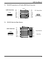
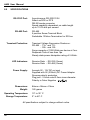
1
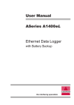
User Manual ASeries A450 Interface Converter RS-232 ó RS-485 Multi-drop the interfacing specialists A450 User Manual Version 1.03 October 2000 COPYRIGHTS All rights reserved. This document may not, in whole or part, be copied, photocopied, reproduced, translated, or reduced to any electronic medium or machine readable form without the express permission in writing from Alfatron Pty Ltd. Copyright 2000 © Alfatron Pty Ltd DISCLAIMER Alfatron Pty Ltd has made every attempt to ensure that the information contained in this document is accurate and complete. Alfatron Pty Ltd makes no representation or warranties of merchantability or tness for any particular purpose. Alfatron Pty Ltd reserves the right to make changes to this document at any time, without notice. Therefore, Alfatron Pty Ltd assumes no liability for damages incurred directly or indirectly from errors, omissions or discrepancies with the hardware and the manual. TRADEMARKS All Company and Product names are trademarks of the Company or Manufacturer respectively. WARRANTY Alfatron warrants its products against defects in materials and workmanship for a period of one year from receipt by the customer. All warranty is carried out on a return to depot basis unless an alternative warranty coverage has been arranged. WARRANTY EXCLUSIONS The above warranty shall not apply to defects resulting from improper or inadequate maintenance by the customer, unauthorised modications or misuses, operation outside the environmental specications for the product, damage due to power surges, lightening strikes or any other phenomenon outside normal operational specications. Alfatron Pty Ltd ABN: 65 005 410 819 P.O. Box 4161 Unit 9/36 New St. Ringwood VIC 3134 AUSTRALIA Web Site: www.alfatron.com.au A450 User Manual 1.0 PRODUCT DESCRIPTION An RS-232 to RS-485 point-to-point or multi-drop interface converter incorporating the following features: l l l l l l l l l Screw terminal connection for RS-485 DCE/DTE switch selectable RS-232 uses DB25 connector Transient Voltage Supression diodes used on RS-485 lines Transmit data at up to 115.2Kbps Transmit RS-485 up to 1200 metres Non-powered RS-485 operation up to 100 metres using point-to-point RS-485 multi-drop up to 32 driver and 32 receivers on 4-wire setup Switchable termination resistors for RS-485 port Monitor mode on RS-485 bus for fault diagnosis RS-232 (RD) DCE /DTE Switch RS-232 Port SW1 RS-485 (RD) Power Jack RS-485 Port ON 2.0 INSTALLATION Before installing the A450 please make sure that the DIP Switch settings are according to the requirement of the RS-485 target device. It is also important to select the RS-232 port as DCE or DTE. Make sure that none of the RS-485 lines are shorting onto the case and after all cables have been connected and secured, insert the power plug into the jack socket and turn the power ON. The A450 is now ready for use. 2.1 LED indicators The LEDs will operate only if DIP Switch 7 is set to the 'ON' position. The RD (RS-232) LED indicator will ash each time data is being received by the Serial RS-232 Port. The RD (RS-485) LED indicator will ash each time data is being received by the RS-485 Serial Port. These LEDs will not operate at any other time. 3 A450 User Manual 3.0 INTERFACE APPLICATION NOTES 3.1 Using RS-485 in 2-wire mode To use a 2-wire bus, simply connect together TX+ and RX+ to form the common BUS+ (or BUSa) line, and RX- with TX- to form the common BUS- (or BUSb) line. When running a 2 wire RS-485 bus the RS-485 transmitter must be controlled by the RS-232 serial device. This transmitter may be controlled by either the RTS/CTS or DTR/DSR handshake pairs. If the RS-232 side is using software to control devices then it may require a local echo of what it transmits, if so, turn DIP Switch 6 to the 'OFF' position. Also, if the distance of the RS-485 device is less than 100 metres then it is not necessary to terminate the RS-485 bus. In a typical setup, DIP switches 6 & 2 would both be set to 'ON' so that the tramsmitter would be controlled by the RTS/CTS handshake pair. Example of a typical 2-wire setup: RD RD TD RTS CTS CTS RTS RD+ SG SG GND TDTD+ RD- Bus- A450 Bus+ RS-232 Device TD RS-485 Dev (1) RS-485 Dev (2) 3.2 Using the RS-232 Port The RS-232 connection is switchable between DTE or DCE. To connect to a PC with a straight through serial cable, chose DCE. Power is drawn from CTS/RTS and DTR/DSR, therefore it is necessary to connect these if the A450 is to be used in non-powered mode. In most applications, it is necessary to connect all of the commonly used pins on the RS-232 port ( i.e. 1, 2, 3, 4, 5, 6, 7, 8 and 20 on a DB25 interface). 4 A450 User Manual 3.3 Using A450s as RS-232 Line Extenders A pair of A450s may be used to extend the distance at which RS-232 data is transmitted. The A450s are connected via their RS-485 ports to take advantage of the greater data transfer distances available using RS-485. The following is an example of the cable which is recommended to connect two A450s together via their RS-485 ports: A450 3.4 TD - TD - TD + TD + RD - RD - RD + RD + GND GND A450 Transient Protection Power surges, or electrical transient voltages, can be induced into cabling by such things as lightning strikes, electric motors, switches and the operation of heavy industrial equipment. The use of long cables also increases the exposure to transient voltages. A transient of the correct magnitude can destroy an unprotected interface converter. It is also possible for certain transients to pass though an unprotected interface converter and cause damage to the equipment which is attached. By using High Speed Transient Voltage Suppressors on its communication lines, the A450 absorbs much of the transient energy on these lines and helps clamp these surge voltages to a safe level. This will ensure that both the A450 and any connected equipment are protected from damage due to transients. The A450 uses a Transient Voltage Suppressor Diode on each of the following: l Transmitter pair TX+ and TX- l Receiver pair RX+ and RX- Each diode has a response time of less than 1ps, power dissipation of 1500 Watts for 1ms and a steady state power dissipation rating of 5 Watts. 5 A450 User Manual 4.0 HARDWARE CONFIGURATION 4.1 RS-485 DIP Switch Settings Switch ( 1 2 = ON 3 = OFF ) 4 Function 5 RS485 transmitter Enabled when DTR/DSR is High RS485 transmitter Enabled when RTS/CTS is High RS485 transmitter ALWAYS Enabled RS485 transmitter NEVER Enabled Monitor Mode DIP Switch 6 7 8 4.2 Function Setting OFF RS485 receiver always enabled (local echo for 2-wire RS485) ON RS485 receiver enabled only when RS485 transmitter disabled OFF LEDs always OFF. Saves power in 'non powered' operation ON LEDs indicate RD/TD Data Flow OFF No termination on RS485 receiver ON 120ohm termination on RS485 receiver Default Factory DIP Switch Settings l l l l RS-485 Transmitter ALWAYS enabled RS-485 Receiver ALWAYS enabled (local echo for 2-wire RS-485) LEDs indicate RD/TD Data Flow No Termination on RS-485 Receiver ON 1 2 3 4 5 6 DCE < > DTE Factory Default for the RS-232 Port is DCE 6 7 8 A450 User Manual 5.0 INTERFACE PORT PIN ASSIGNMENTS 5.1 RS-232C Serial Port Pinout Pin 5.2 Status Set for DCE Set for DTE 1 Used Frame Ground Frame Ground (FG) 2 Input / Output RD TD 3 Output / Input TD RD 4 Linked to Pin 5 CTS RTS 5 Linked to Pin 4 RTS CTS 6 Linked to Pin 20 DTR DSR 7 Used Signal Ground Signal Ground (SG) 8 Not used-Pulled High 4K7 DCD DCD 20 Linked to Pin 6 DTR Note: Pins 4, 5, 6, 8 and 20 are pulled to the correct levels to allow a PC serial port to operate under most conditions without any additional loopback connections. DSR RS-485 Serial Port Pinout TD TD + RD RD + GND 7 A450 User Manual 6.0 CABLE REQUIREMENTS Alfatron recommends the use of shielded cable with all of its products. Shielding reduces EMI Radiation and improves noise immunity. This helps minimise interference to other equipment and will improve communications reliability. The recommended cable construction is as follows: l l Take the shield (surrounding cable wires) and solder it to the Frame Ground (FG) pin. If FG is not available, use Signal Ground (SG) but in this case always use a separate wire for ground which is connected at both ends. The shield must be connected at both ends of the cable. 7.0 CABLE EXAMPLES 7.1 RS-485 Cable from A450 to User Device A450 TD - RD - TD + RD + RD - TD - RD + TD + GND SG User Device FG 7.2 RS-232 Connection to a PC with a DB-25 Serial Connector Shield A450 Cable End DCE (DB-25 Male) 8 FG RD TD CTS RTS DTR SG DCD DSR 1 2 3 4 5 6 7 8 20 1 2 3 4 5 6 7 8 20 FG TD RD RTS CTS DSR SG DCD DTR PC Cable End DTE (DB-25 Female) A450 User Manual 7.3 RS-232 Connection to a PC with a DB-9 Serial Connector Shield A450 Cable End DCE (DB-25 Male) 7.4 RD TD CTS RTS DTR SG DCD DSR 3 2 7 8 6 5 1 4 2 3 4 5 6 7 8 20 TD RD RTS CTS DSR SG DCD DTR PC Cable End (DB-9 Female) RS-232 Cable for Other Devices Shield A450 Cable End DCE (DB-25 Male) FG RD TD CTS RTS DTR SG DCD DSR 1 2 3 4 5 6 7 8 20 FG TD RD RTS CTS DSR SG DCD DTR User Device Cable End 9 A450 User Manual 8.0 SPECIFICATIONS RS-232C Port: Asynchronous RS-232C/V.24 Select as DCE or DTE DB-25 female connector Speed capability dependant on cable length up to 115.2k bits per second RS-485 Port: RS-485 5 position Screw Terminal Block Switchable 120ohm Termination for RD line Transient Protection: LED Indicators: Power Supply: Dimensions: Weight: Operating Temperature: Stroage Temperature: Transient Voltage Supression Diodes on: RS-485 - TX+ and TX- RX+ and RXSurge capacity of 1500 Watts per device at 1ms. Response Time of less than 1ps. Steady state power dissipation rating of 5 Watts. Receive Data - RS-232 (Green) Receive Data - RS-485 (Green) Accepts 9V - 12V DC on input Supplied with 9V (200mA) DC Power Adapter Reverse polarity protection Plug jack - 5.5mm outer/2.5mm inner diameter Polarity is Outer Negative + 84mm x 58mm x 23mm 160 grams 10° to 35° C 0° to 45° C All specications subject to change without notice 10 N42 DECLARATION OF CONFORMITY according to the European Commissions EMC Directive 89/336/EEC We, of, Name of Manufacturer: Address of Manufacturer: Australian Company Number: ALFATRON PTY. LTD UNIT 9, 36 NEW ST. RINGWOOD VIC 3134 AUSTRALIA ACN: 005 410 819 declare under sole responsibility that the product: Product Name: ASeries RS-232 <> RS-485 Interface Converter Model Number: A450 to which this declaration relates is in conformity with the following standards: CISPR-22 / EN 55022 class B IEC 801-2 / prEN55024-2 IEC 801-3 / prEN55024-3 IEC 801-4 / prEN55024-4 AS/NZS:3548ß1995 EMI from Information Technology Equipment (ITE) Electro Static Discharge Immunity Radiated RF Immunity Electrical Fast Transients Immunity EMI from Information Technology Equipment (ITE)