1
1.1
Gold Power Controller
The Gold Power Controller is the hub of the drive system and the interface between
the driver and the motor. It has five high power connection points and a number of
low power digital and analog I/O ports that are accessed through various connector
sockets.
1.1.1 High Power
Two of the high power connection points, marked with +/- labels are for the voltage
bus. The controller and all peripheral products are powered from this power source,
unless otherwise stated. Breaking this power supply will disable all driving
capabilities of the controller. Residual charge in components will operate the
controller for a very brief time, after which the controller will become inert, disabling
any functionality of the electronics.
WARNING: The main supply to the controller should never be turned off whilst the
controller is still under load ie driving the motor.
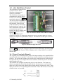
The remaining 3 high power connection terminals (labelled A, B & C in Figure 1) are
the three phase connections from the motor.
Note: Cable lugs should be firmly attached by nuts in the screw terminals. Users
should avoid excessive tightening of these terminals as they can cause physical
stresses on internal circuitry that can lead to a reduced product life. All cables and
connectors should be rated appropriately and are chosen at the discretion of the user.
1.1.1.1
Protection
Tritium recommends that users should always fuse the connection between the high
power source and the motor controller. The fuse should be placed inline and be
preferably a DC fuse of the fast-blow variety. Doing so will minimise damage to the
controller caused by an external high power fault.
1.1.2 Controller Front Panel
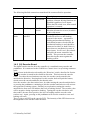
Figure 2. The front panel of the motor controller
© Tritium Pty Ltd 2003
2