1
1.4
(IV.) Gold Driver Control
The Gold Driver Control acts as
a junction box for driver
interfaces, telemetry and
controller commands.
The Gold Power Controller (I.)
communicates with the Driver
Control via a custom RS-485
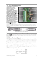
serial cable, shown in Figure 9.
The driver control sends the
requested driving conditions to
the controller, which in turn
sends all telemetry information
back to the driver controls. For
more information regarding the
communications protocol
between the driver controls and
the motor controller refer to
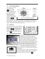
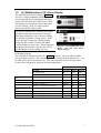
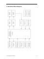
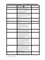
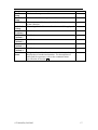
Figure 8. Connector functions of the Gold Driver Display
Section 6.
The standard DB-9 serial
connector is an RS-232 output port designed to convey telemetry data to a wireless
modem or computer for performance analysis. The baud rate for this port is fixed at
115200bps.
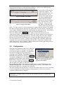
Figure 9. RS-485 Cable plugs and socket.
There is also a 6-way locking connector that goes to the Digital Encoder (refer to
Section 1.4.2) and two IDC output ports that send selected telemetry data to the Gold
Driver Displays (V.). Up to six Driver Displays can be ‘daisy chained’ on each IDC
ribbon cable.
1.4.1 Screw Terminals (Signals)
The 16 green screw terminals require some of the input switches to be attached before
operation of the motor controller. All of these switches should be normally-open two
position. The current and voltage levels used by the control board are small and will
not supersede the power ratings of the chosen switches and do not pose an electrical
shock hazard to the user.
The terminals are arranged in connection pairs for each function. The inputs are
adjacent to each other and will be labelled with the function name on one terminal
input and ‘GND’ on the other. Both of these inputs must be connected to work. Each
input pair also has a corresponding LED on the PCB. This LED will turn on when the
switch is in the ‘on’ position.
© Tritium Pty Ltd 2003
5