1
1.5
(V.) Multifunction LCD Driver Display
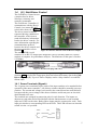
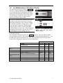
The Multifunction Driver Display (Figure 10,
top) uses a single pushbutton, labelled ‘Select’,
to cycle through four predetermined telemetry
values delivered from the Gold Driver Control.
The displays are 8-segment numeric and show
up to four digits. They are connected and
powered by an IDC ribbon cable.
The motor controller uses PWM control when
driving forward and current control in regen.
This control behaviour can be observed using
the Throttle and Motor Current values. If the
user is driving forward, the Throttle display
changes as the encoder is turned and Motor
Current displays a fixed value. When changing
into Regen, the Throttle value becomes fixed
and the Motor Current reading will vary.
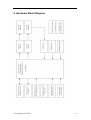
Figure 10. The Multifunction LCD
Display (top) and LED Status
Display (bottom).
LED Status Display
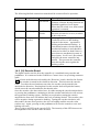
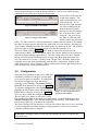
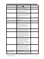
The LED Driver Display is shown in Figure 10 (bottom). The two indicator lights
(left and right) are green. The remaining LEDs – Forward, Neutral and Reverse – can
be either red or green when turned on. The following table shows how these three
LEDs will be arranged for different driving arrangements.
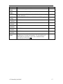
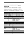
LEDs
Direction Switch is Off
(FWD)
Situation
Forward
Neutral
Reverse
Kill Switch is Off
LH or RH Brake Switch is On (braking)
Off
RED
RED
GREEN
Off
RED
Throttle = zero (controller in neutral)
Throttle > 0 (driving)
Throttle < 0 (regenerative braking)
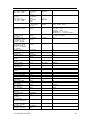
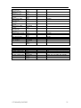
GREEN
GREEN
Off
GREEN
Off
Off
Off
Off
RED
Throttle = zero (controller in neutral)
Throttle > 0 (driving)
Throttle < 0 (regenerative braking)
Off
Off
RED
GREEN
Off
Off
GREEN
GREEN
Off
Direction Switch is On
(REV)
© Tritium Pty Ltd 2003
7