1
Techniques such as GPS measurements and LIDAR aerial laser scanning, supplemented by
conventional surveying, can be used to obtain large amounts of levels efficiently.
Inspections are needed to define many aspects of drainage systems, such as low points on roadways
and likely overflow paths. It is likely that the same areas may have to be inspected two or three times
during modelling to define drainage components and paths exactly. Information can also be sought from
residents about their experiences of flooding during these visits. Closed circuit television (CCTV)
investigations can provide detailed information on pipes and defects such as erosion, cracks and faulty
joints.
If resources are available, the drainage system may be gauged to record storms rainfalls and
corresponding drainage system flows that can be used to calibrate models. Rainfalls are usually
recorded by tipping-bucket raingauges and pipe and channel flows by magnetic or laser-Doppler flow
meters. Gauging for a period of at least 3 months will probably be necessary. When the model is run
with recorded data, the times of flow can be varied by altering values in the spreadsheet output and reinserting these into DRAINS. The DRAINS model can be calibrated or 'tuned' so that the times of the
calculated hydrograph peaks match those of the recorded ones. A similar process can be carried out by
varying the Hydrological Model parameters and percentages of land use, to make the calculated flow
peaks or volumes match the recorded ones. This is more difficult because pervious areas may only
contribute flows in larger storms, and the gauging period may be too short or dry to record significant
runoff-producing storms.
From the available mapping and the survey data, DXF or DWG drawings can be prepared, and a suitable
file prepared with the three layers containing pits (as circles), pipes and a background. DXF files then
can be imported into DRAINS to provide the initial file for the data entry and modelling processes.
As in Design, it will be necessary to develop a set of guidelines on matters such as:
•
the definition and modelling of flow paths,
•
the factors used in pit inlet capacity relationships for the various kinds of pits encountered in the
drainage system,
•
pit blockage factors,
•
existing pipe roughnesses and shapes, and
•
the modelling of ponding of stormwater in streets and backyards.
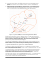
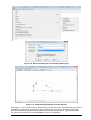
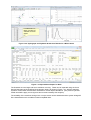
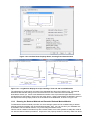
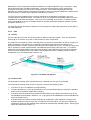
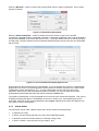
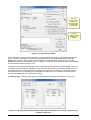
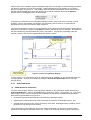
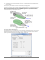
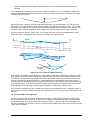
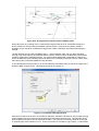
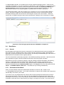
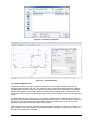
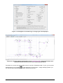
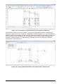
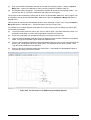
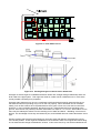
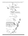
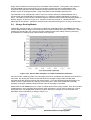
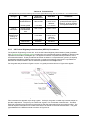
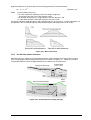
In modelling existing systems, a difficult issue will be the definition of the flow paths taken by flows from
paved and grassed surfaces, as shown in Figure 4.12. These will be greatly influenced by the size and
arrangement of allotments and the buildings on them, and especially by the style of fencing along
allotment boundaries.
If there was no fencing, or if flows could easily pass under fences, the flows would follow the land
contours and the definition of paths and overland flow lengths, slopes and roughnesses would be
relatively easy. Once flows have to pass through fences, or be directed along them, the situation
becomes quite complex, with some storage effects probably coming into play. Even in a detailed analysis
with abundant scope for survey data collection, it would be prohibitively expensive and complex to model
each property’s drainage system and to include possible storages. Some judgements about overall or
average effects must therefore be made. Calibration with gauged data would be particularly useful for
refining these judgements.
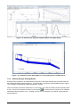
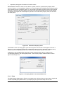
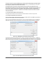
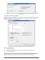
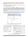
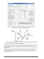
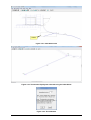
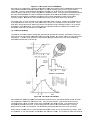
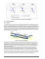
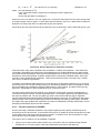
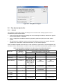
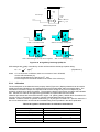
Another difficult issue will be the ponding of stormwater on streets and in backyards. This occurs where
development has occurred in the natural floodway areas, and various barriers to flow have been erected,
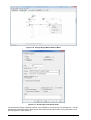
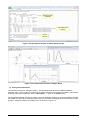
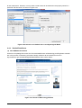
including road crowns, road embankments, walls and fences. It is fairly easy to see where stormwater
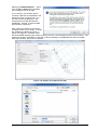
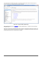
will run into properties. Usually those on the downstream side of a road at a low point will be affected, as
shown in Figure 4.13.
DRAINS User Manual
4.15
November 2014