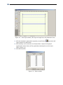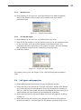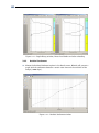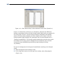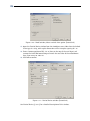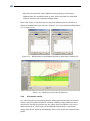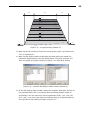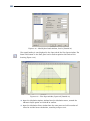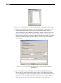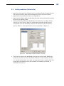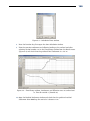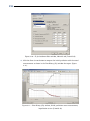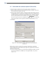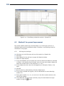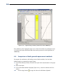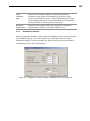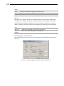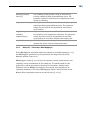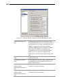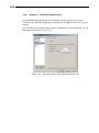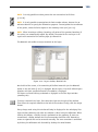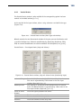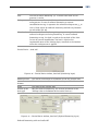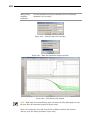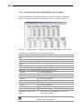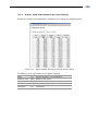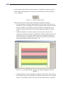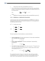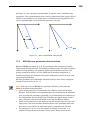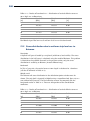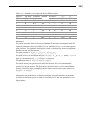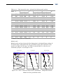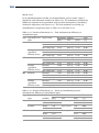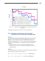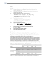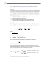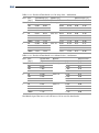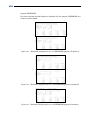
1
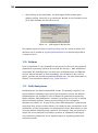
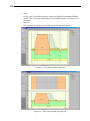
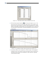
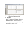
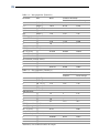
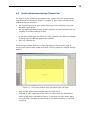
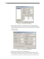
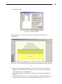
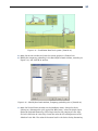
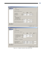
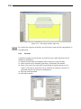
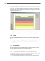
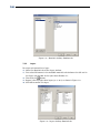
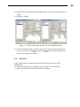
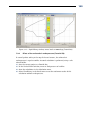
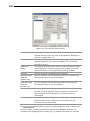
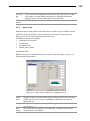
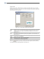
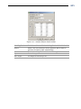
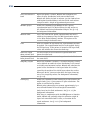
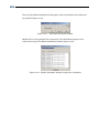
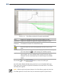
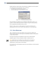
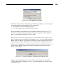
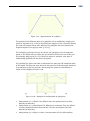
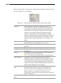
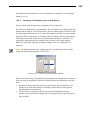
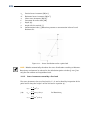
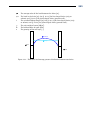
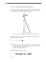
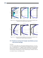
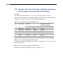
148
MSETTLE USER MANUAL
29. Enter two points using the Add row
<37.5> and Y co-ordinate of <-4.85>.
button with X co-ordinate of <-37.5> and
The excavation is modelled by simply adding a reversed initial non-uniform load at
time 0, by means of a negative unit weight:
30. Click the Add button and rename the load to <Excavation>.
31. Unmark the Initial load checkbox.
32. Enter a Time of <0 days> and a Total unit weight above and below phreatic level of
respectively <-14.4 and <-18.7> kN/m3.
33. Enter the co-ordinates of the excavation boundary given in Figure 7-11 (left).
The filling with sand material is modeled by applying a non-uniform load (with the
same unit weight as the sand material) until the ground surface:
34. Select the previously defined load Initial state, and click the Add button. Rename
the load to <Fill>.
35. Unmark the Initial load checkbox and enter a Time of <12> days.
36. Enter a Total unit weight above and below phreatic level of respectively <17.5>
and <20> kN/m3. The co-ordinates don’t need to be modified, as the top
boundary of the Fill load is the same as the Initial state load (Figure 7-11, right).
Figure 7-11 – Non-Uniform Loads window, Initial state and Excavation loads
7.5.2
Modelling the embankment construction
The sand embankment construction is modelled by applying a non-uniform load with
the unit weight of sand and with the embankment profile:
37. Click the Add button. Rename the load to <Embankment>.
38. Enter a Time of <39> days.
39. Enter a Total unit weight above and below phreatic level of respectively <17.5>
and <20> kN/m3. The position of the foil is given in the table of co-ordinates in
Figure 7-12 (left).