1
CPC
March 1999
Contents
INTRODUCTION ..................................................................................................................................... 4
ABOUT V3, MODIFIED V2 ......................................................................................................................... 4
MPC FUNCTIONALITY .......................................................................................................................... 6
CPC ............................................................................................................................................................ 7
SIGNAL SPLIT ........................................................................................................................................... 7
MAJORITY LOGIC ..................................................................................................................................... 7
READ OUT CONTROL LOGIC ....................................................................................................................... 8
CARD IDENTIFICATION.............................................................................................................................. 9
JTAG.........................................................................................................................................................10
JTAG CHAINS .........................................................................................................................................11
MASK AND TEST PATTERN ........................................................................................................................12
MAJORITY LOGIC ....................................................................................................................................14
SCINTILLATOR CPC ................................................................................................................................19
READ OUT CONTROL LOGIC ......................................................................................................................23
TDC PROGRAMMING ...............................................................................................................................28
14.1. JTAG instructions .................................................................................................................... 29
14.2. Boundary scan register. ........................................................................................................... 29
14.3. ID code.................................................................................................................................... 30
14.4. Setup registers ......................................................................................................................... 30
14.5. Control registers...................................................................................................................... 32
14.6. Status registers ........................................................................................................................ 32
14.7. Internal test registers............................................................................................................... 32
Figures
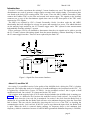
Figure 1: Signal flow from muon chambers .....................................................................................................4
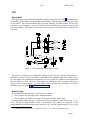
Figure 2: CPC signal split, mask and test pulse ...............................................................................................7
Figure 3: MACH_PROG, programming port .................................................................................................10
Figure 4: JTAG2, emulated port ....................................................................................................................10
Figure 5: Chain orders and connector names .................................................................................................11
Figure 6: Majority output logic ......................................................................................................................17
Figure 8: JTAG, the TDC chain ....................................................................................................................28
Tables
Table 1: MPC registers....................................................................................................................................6
Table 2: MPC Control register.........................................................................................................................6
Table 3: MPC status register............................................................................................................................6
Table 4: MachPro connector ..........................................................................................................................10
Table 5: Mask/ test pattern, Instruction register .............................................................................................12
Table 6 : Testmode select ..............................................................................................................................12
Table 7: Majority logic, Instruction register ...................................................................................................14
Table 8: Majority logic, Set up.......................................................................................................................15
Table 9: Majority logic, Control ....................................................................................................................15
Table 10: Majority logic, input stretcher timing.............................................................................................17
Table 11: Majority output stretcher................................................................................................................18
Table 12: Scintillator, Instruction register......................................................................................................19
Table 13: Scintillator control register ............................................................................................................20
Table 14: Scintillator, stretch and delay.........................................................................................................22
Table 15: Scintillator, test point selector ........................................................................................................22
Table 16: Read Out Control, JTAG register selection.....................................................................................23
Table 17: Read Out Control: Control register ................................................................................................24
Table 18: Read Out Control: Setup register....................................................................................................25
Table 19: Read Out Control, Diagnostics register ..........................................................................................25
page 2