1
CPC
March 1999
three muon chamber layers; MI, MM or MO. A register setting determines which output has
to be activated. This output is a differential implementation of an open collector output. In
this way all CPCs in a crate can pull this line. This line then runs to the CTT (Cosmic Trigger
and Timing) module, where the Cosmic trigger is generated.
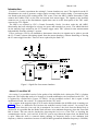
In every P-crate there is one location where signals from two different muon chamber layers
are connected to one FastBus TDC. In that case the majority logic works in the splitted
mode, with two times 48 channels. Two output signals are generated in the same way as
described above and can be routed (software controlled) to the MI, MM and MO outputs.
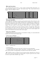
The majority logic chip (IC 8) receives the 40 MHz clock from the read out chip (IC 7).
This clock is divided internally to create the clock for the pulse stretchers and other pipe line
registers. This divider can be programmed to divide from 7 to 10.5 in eight steps. The setting
is done via JTAG. The pipe line clock periods thus vary from 175 to 263 ns, in 12.5 ns steps.
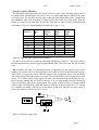
The pulse stretchers are active for seven of these cycles. So the one shots run for 1050 to
1575 ns, plus one clock period. The input signal is first stored in a register. On the next clock
cycle the one shot starts. This covers the maximum drift time plus one clock cycle for the
synchronization uncertainty. Also one clock cycle overlap is needed to determine the total of
active one shots. The drift time range is then 1050 to 1575 ns. For information how to set the
stretchers see page 14. The reset signal from the FELink can be used to synchronize the
clock dividers on the different CPCs.
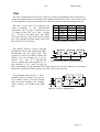
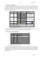
For the scintillators the chip that normally contains the majority logic (IC 8) has an other
contents. It logically ORs every eight inputs, which results in 12 signals. These signals can be
used by three outputs to form larger ORs. These three outputs are first stretched and then
delayed. The stretcher is a retriggerable one-shot that is fired by the rising edge of the OR
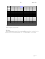
signal. The delay is made by means of a shift register. For the settings see Table 14:
Scintillator, stretch and delay.
Read out control logic
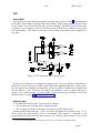
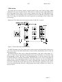
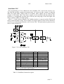
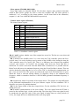
The CPC Read Out Controller (ROC) in IC7 receives the clock (40 MHz) and control
signal (Reset/Trigger) from the NIMROD. The control signal encodes the Reset and Trigger
signals using a 3 bit pulse width scheme. Holding the control line high for one clock cycle,
followed by a low level for at least two clock cycles encodes the Trigger signal. Holding the
control line at high level for three consecutive cycles encodes the Reset signal.
The Reset and Trigger signals are distributed to the TDC chips and the Majority logic chip.
The Reset signal clears all internal counters and the data memory in the TDC chips. The
Trigger signal is used by the ROC to initiate the read out of the TDC chips. The data from
the TDC's is read out using a token ring scheme and the data is formatted by adding some
identification bits, serialized and sent to the NIMROD via the Front End Link. Data is
transferred via two pairs of Low Voltage Differential Signal (LVDS) drivers using the DataStrobe (DS) protocol. The bit rate is 40 Mbit/s and each data word is composed of a start
bit, 32 data bits, a parity bit and one stop bit. This results in a maximum data rate of
approximately 1 Mword/s.
Provisions have been made to be able to read out the Majority Logic as another node in the
token ring. This would allow the Majority Logic to send one word of information into the
data stream after a Trigger, whenever that becomes useful.
page 8