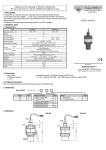
1
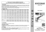
3. INSTALLATION
Before mounting the unit in its final position, make sure that the programming points of the unit are accessible with the supplied magnet, the LEDs
are clearly visible and the level of the liquid can be changed between its minimum and maximum during the programming session. If any of the
above conditions are not met, the programming should be carried out before mounting the unit in its final position. (See 5. Programming)
When mounted on a pipe, we recommend the use of the SAA-110 transparent pipe connector that enables on-site programming.
r
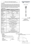
Wind:
Intense movement of the air may effect the ultrasonic
measurement and cause inaccuracy or eventually make it fail.
Vapors, fumes:
Vapors and fumes of gases may radically reduce the measuring
range of the device (e.g.: chemicals, outdoor tanks under
sunshine).
Stand-off pipe:
The structure of the stand off pipe should be rigid, the inner rim
where the ultrasonic beam leaves the pipe should be rounded.
d
Obstacles:
No object should protrude into the
ultrasonic beam of the device
(e.g.: ladder, thermometer, etc.).
Foam:
Foam on the surface of the liquid can
make ultrasonic measurement difficult
or eventually make it fail.
Mount the device in a location where
foam building is minimal or use a
stilling pipe.
≤ 250
≤ 350
L
D ≥ ∅100
D ≥ ∅100
Dmin
150
200
250
Ø 60
SC 340
*
Ø 65
*
Ø 75
*
450
–
*
SC 380
L
Positioning:
The optimal position of the EasyTREK
is between r=(0.2 to 0.4)d of the tank.
This will prevent unwanted interference
caused by dome-top tanks.
The sensor face has to be parallel with
the surface of the liquid within ± 2°.
L
ATTENTION!
Dmin.
Dmin.
Temperature:
The transmitter should be protected against overheating (e.g. by direct sunshine) to avoid inaccurate measurement.
4. ELECTRICAL INSTALLATION
Brown
Green
Yellow
Pink
Grey
White
Shielded
Cable
Green LED
Red LED
"ECHO"
Top view of the neck section
T
R
A
N
S
M
I
T
T
E
R
Brown
Green
Supply voltage
Iout
Current
Output
GND
Power Supply
11.4…28V AC v.
11.4…40V DC
Gray
White
Yellow
Pink
Relay
Output
Shielding
Junction box
Denotation of the color wires:
− Brown
Power supply
− Green
Power supply
− Yellow
Relay output
− Pink
Relay output
− Grey
Current output
− White
GND
− Shielding
To be grounded
In case of DC power supply the unit is polarityindependent.
The relay is NO type
Three-wire installation is possible in case of DC power
supply by connecting the GND and the (-) pole of the
power supply. In this case galvanic isolation is not
provided.
Extending the cable:
− When extending the cable, use a junction box. Shielding of
the unit cable and that of the extension cable should be
connected and grounded at the end of the extension cable.
− Extend only wires required for the purpose of the
application.
5. PROGRAMMING
10
20 Iout
E
F
After wiring of the unit according to para 4 device begin to tick and after
25 … 50 s the ECHO LED would go on and 4 … 20 mA appear at the current output provided
0 4
true echo signal has been found.
For ultimate temperature compensation accuracy, switch on the device 1 hour before 100%
programming.
Programming can be performed in two ways:
• On-site, using the liquid level as reflecting surface (only if the programming points are
0%
accessible on the unit, the LEDs are visible and the level of the liquid can be changed
between the its minimum and maximum during the programming session).
• Off-site, using a flat object as reflecting surface (e.g.: table or wall).
The following features can be programmed using Touch-Magnet Programming with the supplied magnetic screwdriver:
− Assignment of the 4 mA analogue output to a required min. level / max. distance (E) (factory default: XM max. measuring distance)
− Assignment of the 20 mA analogue output to a required max. level / min. distance (F) (factory default: Xm min. measuring distance)
− Error indication by the current output
(factory default: hold last value)
− Relay switching differential (if not programmed the relay is for echo loss indication)
(factory default: echo loss indication, relay NO)
– Damping
(factory default: 60 sec)
Note: Current output can also be assigned in inverted mode:
F ≥ xm
E ≤ xM
4 mA = 100 %, 20 mA = 0 %
ATTENTION! When using off-site calibration, distance between the reflecting object and the unit must correspond to the required 4/20 mA values.
[mA]