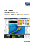
1
User’s Manual EIVA Online Eventing Tool NaviPac - NaviEvent - EventEdit - NaviPlot December, 2009 User’s manual – EIVA Online Eventing Tool User’s Manual 8-10 Teglbækvej DK-8361 Hasselager – Aarhus, Denmark EIVA Eventing Tool Tel: Fax: +45 8628 2011 +45 8628 2111 e-mail: Web: [email protected] www.eiva.dk NAVIPAC - NAVIEVENT - EVENTEDIT - NAVIPLOT December 2009 1 Covering revision 1.0.0.5 Lars Dall NZO/APJ 08/12/2009 0 First Edition Lars Dall NZO/APJ 03/07/2008 By Checked Revision Description Key words: Approved Date Classification Open Eventing, Online Internal Proprietary Distribution N/A Eventing Tool No of copies N/A Page 2 of 59 N/A Rev. no. 1, 2009-12-08 User’s manual – EIVA Online Eventing Tool CONTENTS 1. INTRODUCTION ................................................................................................................. 4 2. ONLINE EVENTING ............................................................................................................ 7 2.1 The NaviEvent tool .......................................................................................................... 7 2.1.1 Starting NaviEvent............................................................................................. 7 2.1.2 Common Tools .................................................................................................. 8 2.1.3 The Main Menu ............................................................................................... 10 2.1.4 Configuring an Event Job ................................................................................ 12 2.1.4.1 Settings Mode ............................................................................................. 12 2.1.4.2 Design Mode .............................................................................................. 21 2.1.5 Utilizing the NaviEvent tool.............................................................................. 24 2.2 NaviPac in support of online eventing ........................................................................... 26 2.2.1 NaviPac Configuration..................................................................................... 26 2.2.2 NaviPac Online................................................................................................ 29 3. EDITING EVENTS ............................................................................................................. 33 3.1 Editing of events within The EventEdit Tool .................................................................. 33 3.1.1 The Main Menu ............................................................................................... 34 3.1.2 Editing the fields .............................................................................................. 37 3.2 Editing of events within NaviEdit ................................................................................... 39 4. NAVIPLOT EVENTING ...................................................................................................... 44 4.1 General Introduction to NaviPlot ................................................................................... 45 4.2 Configuring an Events Profile ........................................................................................ 47 4.2.1 Adding a header strip ...................................................................................... 50 4.2.2 Adding a single event strip .............................................................................. 51 4.2.3 Adding a range event strip .............................................................................. 53 4.2.4 Adding a counter event strip............................................................................ 54 4.3 Importing Comma-separated files ................................................................................. 56 4.4 Showing Events in the XY window ................................................................................ 56 4.5 Final Output ................................................................................................................... 58 Eventing Tool Page 3 of 59 Rev. no. 1, 2009-12-08 User’s manual – EIVA Eventing 1. INTRODUCTION The purpose of the present Eventing Manual is to provide a guide on how to perform online eventing in the EIVA Hydrographical Software Suite. The scope of the manual includes the dedicated online eventing tools, NaviEvent and EventEdit, whereas the traditional/classic event tool supplied through NaviPac, will only be described whenever deemed necessary for the proper understanding of these dedicated tools. The more traditional approach to online eventing is thoroughly described in the various NaviPac software manuals. The scope furthermore includes the handling of online events in NaviPlot. Offline eventing is described in the dedicated user‟s manual „EIVA Offline Eventing‟ and will thus only be dealt with, in the present context, in situations where this is deemed necessary for the enhancement of the understanding of online eventing. The Online Eventing Manual is sub-divided into three main chapters, each related to online eventing at a distinct level of the online/offline process: Online Eventing, Editing Events, and Plotting Events. The Online Eventing part is furthermore subdivided into a configuration part and an online part. Additionally online eventing is presented in connection with the „traditional‟ EIVA software packages, NaviPac, NaviEdit and NaviPlot. In the present context, each of these presents a level of the online eventing: NaviPac is associated with generating events, NaviEdit is associated with editing events and NaviPlot is associated with plotting events. Eventing Tool Page 4 of 59 Rev. no. 1, 2009-12-08 User’s manual – EIVA Eventing Figure 1 General Flow-diagram, EIVA Software Suite The overall dataflow within the EIVA suite is depicted in Figure 1 above. Note that NaviPac and NaviScan together constitute the on-line part, whereas the offline part of the suite is comprised by NaviEdit/NaviModel/NaviPlot. At the same time, the manual presents EIVA‟s more dedicated eventing tools: NaviEvent and EventEdit. Whereas NaviEvent is executed during on-line sessions, EventEdit is used to edit the events acquired. A visualisation of the overall EIVA event flow can be seen below in Figure 2. Observe that the online eventing flow is depicted in the lines „Configuration‟, „Online Eventing‟, „Editing Phase‟ and „Output‟, whilst the offline eventing phase is added in line „Offline Eventing‟. Whereas the dedicated eventing is shown in the left column of the figure, the actual data-acquisition flow is visualised to the right. The two columns merge together towards the bottom, in connection with the „NaviPlot‟ and the „Output‟ stages, during which a combination between events and dataacquisition is aimed at. Eventing Tool Page 5 of 59 Rev. no. 1, 2009-12-08 User’s manual – EIVA Eventing Figure 2 Event Flow - EIVA Software Suite Eventing Tool Page 6 of 59 Rev. no. 1, 2009-12-08 User’s manual – EIVA Eventing 2. ONLINE EVENTING Figure 3 Eventing Flow - Configuration Mode As visualised in Figure 2, NaviEvent requires NaviPac to be running in online mode while generating online events. At the same time NaviScan and NaviPac might be running together and the positions of interest for the eventing might actually be associated with a NaviScan object. As such the software packages must be configured to take that into account. This is visualised above in Figure 3. Whereas the following is a description on how to implement this into the configuration of NaviEvent, a description on how to implement the settings required for NaviPac to support NaviEvent is given below in chapters 2.2 and 2.2.2. 2.1 The NaviEvent tool The EIVA NaviEvent tool has been developed to meet the growing demand for a comprehensive yet user-friendly online event package that at the same time facilitates integration towards the EIVA offline applications. From the beginning it was regarded a requirement, that the tool would be integrated with the EIVA on-line data-acquisitions and navigation package, NaviPac, and that it, at the same time, would be a distributed solution. A governing requirement was furthermore that the system should be simple to use and yet completely configurable in order to meet specifications for pipeline and cable inspection jobs as well as for general video survey jobs for any client. 2.1.1 Starting NaviEvent When NaviEvent is first started, the window visualised below in Figure 4 will appear. Choose the language of your preference as well as the action to take „Next time…‟ and press „OK‟. Eventing Tool Page 7 of 59 Rev. no. 1, 2009-12-08 User’s manual – EIVA Eventing Figure 4 Selecting NaviEvent language The NaviEvent window will now appear as shown below in Figure 5. Figure 5 NaviEvent - initial view 2.1.2 Common Tools NaviEvent is organized in different panels, menus, modes and views that together make the user interface. An example of the user interface is visualized in Figure 6. Eventing Tool Page 8 of 59 Rev. no. 1, 2009-12-08 User’s manual – EIVA Eventing The various items can be listed as follows. Main Menu Button View On-line mode Design Mode Settings Mode Explorer Panel Properties Panel Message History View Figure 6 NaviEvent - User Interface Eventing Tool Page 9 of 59 Rev. no. 1, 2009-12-08 User’s manual – EIVA Eventing 2.1.3 The Main Menu The main menu has three major entries: „File‟, „Edit‟ and „Help‟. Details on how to set up a NaviEvent job will be given in chapter 0. The following description has therefore been limited to an overall introduction to the various tools. From the „File‟ menu, it is possible to manage the event configuration file (*.ecf). Choose menuitem „File – Open‟ to load a previously saved configuration file (see Figure 7). Choose menuitem „File – Save‟ (or „Save as‟) to save the present configuration onto a file. NaviEvent will remember the previous folder-entry and use it as default folder when activating the file-menu entries. Note that the ecf-files are stored as XML-files that, in principle, can be edited in any ASCII-editor (see Figure 8). In general terms however, it is not recommended to apply changes this way, since check of the validity of the configuration-files has not been implemented into NaviEvent. Figure 7 Opening a Configuration file from the default folder Eventing Tool Page 10 of 59 Rev. no. 1, 2009-12-08 User’s manual – EIVA Eventing Figure 8 Configuration file in ASCII editor The „Edit‟ menu facilitates the following items: „Edit – Show Message History‟ which toggles the message history window on and off „Edit – Design Mode‟ - toggles between design mode and eventing mode „Edit – Settings‟ – opens the settings window (for an example see Figure 9) Figure 9 Settings Window - example The Help-menu does not contain any entries at present. Eventing Tool Page 11 of 59 Rev. no. 1, 2009-12-08 User’s manual – EIVA Eventing 2.1.4 Configuring an Event Job A NaviEvent job is configured in two distinct modes: Define Settings Mode Design Mode To configure a NaviEvent job, first choose menu-item „File – New‟. The user interface now appears as shown in Figure 10. Figure 10 Empty NaviEvent Job 2.1.4.1 Settings Mode Choose menu item „Edit – Settings‟. This action will invoke the settings-window, that initially appears as visualised in Figure 11, below. Eventing Tool Page 12 of 59 Rev. no. 1, 2009-12-08 User’s manual – EIVA Eventing Figure 11 Settings Window - initial view The settings window is divided in two: a) the Explorer Panel to the left and b) the Properties Panel to the right. At first the Properties Panel will be blank. Click and highlight „Connection‟ in the top of the Explorer Panel and see that the properties for the item is visualised in the Properties Panel. The item „Connection‟ refers to the connection between NaviPac (in online mode)/NaviModel3 (in offline mode) and NaviEvent. A series of entries must be defined for the item: Format - at present two formats are supported, „NaviPac‟ (for online applications) and „NaviModel3‟ (for offline applications) In case of offline eventing (NaviModel format), „Name‟ is the only variable that must be defined. In Figure 12 below it appears to the left, that NaviEvent is capable of detecting which possible connections are available on the LAN. The user should choose the connection that is related to the NaviModel3 project in question (Figure 12 right). Observe that NaviEvent will reconnect automatically when the connection for one reason or another has been discontinued In case of online eventing, the following variables must be specified: Protocol - only UDP/IP protocol is supported IP address - is the IP address of the computer that hosts NaviPac Port - is the port to which NaviPac transmits the event data Eventing Tool Page 13 of 59 Rev. no. 1, 2009-12-08 User’s manual – EIVA Eventing Figure 12 Settings Mode - Connection Settings When the „Connection‟-settings have been defined, the Settings window will appear as visualized above in Figure 12. Click and highlight „Logging‟ in the Explorer Panel and see that the properties for the item is visualised in the Properties Panel. The item „Logging‟ refers to the Event logfile that NaviEvent will write its entries onto. Three entries must be defined for this item: Naming Method - four methods are supported and can be selected by the drop-down menu: Fixed filename – no changes applied to the filename By Hour - this method adds „YYYY-MM-DD_hhmm‟ at the end of the filename By Day - this method adds „YYYY-MM-DD‟ at the end of the filename By Runline - this method adds Runline name at the end of the filename File Name – type in the filename. NaviEvent will append the extension txt to the name File Location - Press the browse-button to define the location of the event log-file Eventing Tool Page 14 of 59 Rev. no. 1, 2009-12-08 User’s manual – EIVA Eventing Figure 13 Settings Mode - Logging Settings Once the „Logging‟-settings have been defined, the Settings window will appear as visualized above in Figure 13. Note that there is a help-text panel underneath the Properties Panel. This panel will contain help-information associated with the item highlighted in the properties panel, if any. Finally click and highlight „List of Events‟ in the Explorer Panel and see the properties for the item visualised in the Properties Panel. At first the panel is empty as shown in Figure 14 below: Figure 14 Settings Mode - List of Events, initial view Eventing Tool Page 15 of 59 Rev. no. 1, 2009-12-08 User’s manual – EIVA Eventing The item „List of Events‟ refers to the event-types that can be defined in online mode. The user will need to define these in a sequence similar to what is described in the following. Press the „Add new‟ button. The window below in Figure 15 pops up. Enter the name of the event and press „OK‟. Figure 15 Add event - define name The entry will instantly appear to the left in the „Inactive events‟ List of the Properties Panel as shown in Figure 16. Highlight the event and press the arrow right. The event will now appear in the „Active events‟ list to the right and the „List of Events‟ item in the Explorer Panel will have a + attached to it to indicate that there is now an entry in the list (see Figure 17). Figure 16 Settings Mode - Defining Events step I´ Eventing Tool Page 16 of 59 Rev. no. 1, 2009-12-08 User’s manual – EIVA Eventing Figure 17 Settings Mode - Defining Events step II´ Press the + to „explode‟ the explorer panel item „List of Events‟ and click on the entry „Anode – good condition‟. Now the Settings window appears as depicted below in Figure 18. Figure 18 Settings Mode - Defining Events III Observe that the definition of settings for a number of items is required for the item: Button name – initially this is identical to the event name Button ID – NaviEvent will generate a default ID – this can be changed by the operator to match his desires. Note that the ID will be logged on the on-line phase as a filed in the event log-file Eventing Tool Page 17 of 59 Rev. no. 1, 2009-12-08 User’s manual – EIVA Eventing Shortcut key – a short-cut for the most commonly used buttons can be defined here. Observe that the shortcut key functionality will only work once the NaviEvent program has focus. The default value for the shortcuts is „None‟ (no shortcut). To define, choose from a dropdown menu that will make the window visualised below left pop up. Any combination of modifiers „Ctrl‟, „Shift‟ and „Alt„ together with the remaining keys of the keyboard can be used. Note that the sequence in the modifiers „Ctrl‟-„Shift‟-„Alt„ is fixed and that the „Key‟ is always last. Once defined, the shortcut-item will be shown in the properties panel as shown below right. Also observe that the „Reset‟ button (below left) will reset the shortcut key to „None‟ Color – the color of the event button can be modified – default is grey. To define, choose from a drop-down menu that will make the window shown below left pop up. Three palettes are available from dedicated tabs: „Custom‟, „Web‟ and „System‟. Once defined, the Coloritem will be shown in the properties panel as shown below right. Note that if the color-item has been chosen from the „Custom‟-tab, the color will be visualized as the color together with a combination of RGB. It is thus possible to define colors by entering the desired combination manually (without using the drop-down option) Button size – can be modified from a drop-down menu. Options available are „Small‟, „Medium‟ and „Large‟ that can be chosen from a drop-down menu. Default is „Medium‟ Event type – can be modified from a drop-down menu. Options available are „Basic‟, „Free text‟ and „Incrementing‟. Default is „Basic‟: „Basic‟ type will generate an event with default text, identical to the button name „Free Text‟ type will enable the user to insert a text onto the event Eventing Tool Page 18 of 59 Rev. no. 1, 2009-12-08 User’s manual – EIVA Eventing „Incrementing‟ type will facilitate a count (incrementing) onto the event count text. The default starting value will be 1, but the user can change this when executing the event. Once the initial value has been defined, NaviEvent will increment automatically, by 1. Note that for „Incrementing‟ type the event text will be identical to the button name (identical to the „Basic‟ type). Also observe that the incrementing counts will reinitiate when changes have been applied Note that a detailed description of the contents of a NaviEvent event log-file, including the event text and the event count text, will be given in chapter 2.1.5. Once an event-button has been generated and it has popped up in the explorer panel, it is possible to rename it by clicking twice on the name here and then typing the new name (as seen on Figure 19 below). Figure 19 Renaming an event NaviEvent facilitates the adding of a series of buttons to an event. These buttons will be active in sequence. Start by generating an entry in the „List of events‟. In the example below (Figure 20), an overall event group, „Freespan‟ has been entered. By right-clicking this event group in the Explorer panel, the event settings will appear in the Properties Panel. Press the „Add button‟ to add an event button to the event group. In the example this has been done twice: one is called „Freespan – Touchdown‟ and one is called „Freespan – End‟. These will now appear in the „List of event buttons‟ together with the original event and can be modified, one by one, in the Properties Panel. Note that the original event has been renamed in the „List of buttons for selected event‟ from „Free Span‟ to „Free Span Start‟. Eventing Tool Page 19 of 59 Rev. no. 1, 2009-12-08 User’s manual – EIVA Eventing Figure 20 Settings Mode - Series of events I In on-line mode the buttons will be activated in sequence. In the present context this means that initially the „Freespan – Start‟ button is active, whereas the two others are inactive. Once the „Freespan - Start‟ has been pressed, the „Freespan – Touchdown‟ becomes active and the two others inactive. The „Freespan – End‟ will, in other words not be active until a „Freespan – Touchdown‟ has been encountered. This is most probably not what the user would want. Instead it is advised to generate two events in the „List of Events‟, one called „Freespan‟ and the other called „Freespan – Touchdown‟. The „Freespan‟-event group should be subdivided into „Freespan – Start‟ and „Freespan – End‟ as shown below in Figure 21, whereas the „Freespan – Touchdown‟ should not be subdivided. It is now possible, in online mode, to toggle between „Freespan – Start‟ and „Freespan – End‟ which is what we want. The „Freespan – Touchdown‟ will be available at all times, but it will only be relevant to activate it when „Freespan – Start‟ is active (when there really is a freespan). Observe that the start/stop level will be reset when changes have been applied. Eventing Tool Page 20 of 59 Rev. no. 1, 2009-12-08 User’s manual – EIVA Eventing Figure 21 Settings Mode - Series of events II Once the settings have been defined in the Settings Window, press „OK‟ and NaviEvent will return to the main window. The event job can now be saved by utilizing the menu-item – „File – Save as‟. 2.1.4.2 Design Mode After the settings of the NaviEvent job have been defined, the buttons will be given a default position on the Button View by NaviEvent. In order to modify these positions, choose menu-item „Edit – Design Mode‟. This will toggle the system into Design Mode in which it is possible to move buttons as desired by the operator. Figure 22 below shows the default Button View prior to having applied changes in Design Mode. Eventing Tool Page 21 of 59 Rev. no. 1, 2009-12-08 User’s manual – EIVA Eventing Figure 22 Design Mode - Initial view Having entered design mode the user is given the opportunity to place and organize the buttons by clicking, dragging and dropping them to any place on the canvas. The NaviEvent job shown in Figure 22 appears as shown in Figure 23 after having designed it. Note that the buttons have been organized together in logical blocks. These blocks have, in general terms, been given an identical color in order to facilitate an instant and unambiguous identification. The exception is the event with a start/stop functionality – here the color of the start and stop buttons have been given slightly different colors. Compare the Figure 23 to the figure at the frontpage of the manual. The buttons, including the colors, are identical, but the positions have been altered slightly in Figure 23 to accommodate for the desires of a user. Once the settings have been defined in Design Mode, choose menu-item „Edit – Design Mode‟ to toggle back to online mode. The final event job can now be saved by utilizing the menu-item – „File – Save as‟. Eventing Tool Page 22 of 59 Rev. no. 1, 2009-12-08 User’s manual – EIVA Eventing Figure 23 NaviEvent job - after designing Eventing Tool Page 23 of 59 Rev. no. 1, 2009-12-08 User’s manual – EIVA Eventing 2.1.5 Utilizing the NaviEvent tool Figure 24 Eventing Flow - Online Mode As visualised in Figure 2 and in Figure 24 above, NaviEvent requires NaviPac to be running in online mode while generating online events. A description on how to implement the settings required for NaviPac to support NaviEvent is given below in chapters 2.2 and 2.2.2. In online mode, NaviEvent will generate events in the event log-file on each button-click. The information stored on the file will be depending on the input from NaviPac. It is important to understand, that NaviEvent will store events generated through NaviEvent as well as events received from NaviPac. The latter can be generated either manually or automatically. The automatic events can be either distance- or time-based. If the user wishes to avoid events from NaviPac, he must in other words disable the automatic eventing in NaviPac. At the same time, NaviPac can be set up to log events in the NaviPac event-log (classic). This log will not contain the events generated through the use of NaviEvent. Further note that logging and reception of data from NaviPac will be temporarily terminated while NaviEvent is in Settings Mode. In Edit Mode, however, NaviEvent will still be receiving and logging events and information received from NaviPac. Eventing Tool Page 24 of 59 Rev. no. 1, 2009-12-08 User’s manual – EIVA Eventing Figure 25 NaviEvent format Figure 25 above shows a NaviEvent event-log opened in Notepad. The fields logged are as follows: Event Number - The event identification number – will only contain a number in case of a NaviPac generated event (alternatively 000000 for events generated in NaviEvent) Date of the event (originating from NaviPac) Time of the event (Pc-time) Easting of event-object (from NaviPac) – the object is defined in NaviPac and can be altered in NaviEdit (see details in chapters 2.2.1 and 0) Northing of event-object (NaviPac) DOP/Standard deviation (NaviPac) of event-object position Gyro/heading (NaviPac) of event-object position DAL (Distance Along Line) - (NaviPac) of event-object position - if line was active at the time of the event DOL (Distance Off Line) - (NaviPac) of event-object position - if line was active at the time of the event KP (Kilometer Post) - (NaviPac) of event-object position - if line was active at the time of the event Object - Name of event-object (NaviPac) Height of event-object (NaviPac) - as defined in the Settings Mode of NaviEvent Event information – generated by NaviEvent (“.” when originating from an automatic event in NaviPac – otherwise event-text will be shown). From NaviEvent the text is generated on the basis of “‟event group ‟.‟button name‟” Type of event (from 0 to 7) 00 - Time-based event (from NaviPac) 01 - Distance-based event (from NaviPac) 02 - Manual event (from NaviEvent or NaviPac) 03 - External event (from NaviPac) 04 - Start Logging (from NaviPac) Eventing Tool Page 25 of 59 Rev. no. 1, 2009-12-08 User’s manual – EIVA Eventing 05 - End Logging (from NaviPac) 06 – Forced Time-based event (from NaviPac) 07 - Field Joint event (from NaviPac) Text (not used at present) Text (not used at present) Button ID as defined in the Settings Mode of NaviEvent Button Name as defined in the Settings Mode of NaviEvent – text-value for freetext events Event count text (for incrementing events only) 2.2 NaviPac in support of online eventing The NaviPac on-line data-acquisitions and navigation package facilitates eventing in two different ways: Internal NaviPac eventing External eventing through the EIVA Eventing tool NaviPac can support the two eventing methods simultaneously. Note however, that whereas the external eventing log-file will contain information from the internal as well as from the external eventing, the internal eventing log-file will only contain information regarding the internal eventing. Whereas the external eventing is the main subject of the present User‟s manual, the internal tools will not be discussed in details here. Particulars regarding this more traditional approach to inventing can instead be found on the EIVA Training and Documentation site as well as in the software manuals distributed with the system (primarily in the documents „3_NaviPac Setup‟, „4_Online‟ and „PipeStatusWindow‟). 2.2.1 NaviPac Configuration NaviPac supports the Eventing Tool through a dedicated data output, „NaviPac eventing‟. This output must be defined in the „Instruments Interfacing – Data Output‟ as visualised below in Figure 26: Eventing Tool Page 26 of 59 Rev. no. 1, 2009-12-08 User’s manual – EIVA Eventing Figure 26 Settings for „NaviPac Eventing‟ To implement this output, first click on the data-output item in the Explorer Panel of NaviPac Config and choose the menu-item „Add new item‟ (see Figure 27 below). Figure 27 NaviPac Eventing - Step 1 Now choose type „NaviPac eventing‟ as shown below: Eventing Tool Page 27 of 59 Rev. no. 1, 2009-12-08 User’s manual – EIVA Eventing Figure 28 NaviPac eventing- step 2 The window visualised in Figure 28 will now appear. Choose I/O-type „UDP/IP‟ (prerequisite), select a port and choose the IP-address of the computer where the Eventing Tool will be executed. This could be the computer that hosts NaviPac, but since the Eventing Tool supports a distributed solution, the IP-address could in principle be referring to any computer on the local LAN. Note that it is possible to choose a broadcast address, in case the Eventing information must be distributed to several computers on the network. At this stage the NaviPac object, from which the eventing should be generated, must be defined. This is done from the Config Properties panel as visualised below: When the desired settings of the NaviPac eventing output have been defined, the Config Explorer- and Properties panels will appear as visualised in Figure 26 above. Eventing Tool Page 28 of 59 Rev. no. 1, 2009-12-08 User’s manual – EIVA Eventing 2.2.2 NaviPac Online In general terms, NaviPac facilitates visualisation of data output by the software through the socalled „NaviPac Instrument Spy‟ generic view. So, in order to observe the data transmitted for the Eventing tool, choose menu-item „Options – Instrument Control – Instrument monitor and control‟ as visualised below in Figure 29. Alternatively the dedicated icon will invoke the view. Figure 29 Invoking the Instrument Spy By selecting the instrument „NaviPac eventing‟ from the drop-down list in the upper left corner of the window, the Instrument Spy will appear as shown in Figure 30 below. Observe that NaviPac outputs the event-information each cycle (each second by default (and in the example)). Figure 30 Instrument Spy - NaviPac eventing Eventing Tool Page 29 of 59 Rev. no. 1, 2009-12-08 User’s manual – EIVA Eventing The contents of the fields transmitted depend on a) whether or not NaviPac is logging data and b) whether or not an event has been generated in NaviPac. The comma-separated fields are as follows, in sequence: Event number – will only contain a value in case of a NaviPac generated event (either manually or automatically) Date Time Easting of (event-) object Northing of (event-) object DOP/Standard deviation of position of (event-) object Heading/gyro of (event-) object DAL of (event-) object – will only contain a value in case NaviPac is logging DOL of (event-) object – will only contain a value in case NaviPac is logging KP of (event-) object – will only contain a value in case NaviPac is logging Object Name Height of (event-) object Event text – will only contain a value in case of a NaviPac generated event (generated either manually or automatically) Event type – will only contain a value in case of a NaviPac generated event (generated either manually or automatically) <CR><LF> The Event type field can achieve numbers from 00 to 07 as follows: 00 - Time-based event 01 - Distance-based event 02 - Manual event 03 - External event 04 - Start Logging 05 - End Logging 06 – Forced Time-based event 07 - Field Joint event The events generated internally in NaviPac can be visualized in different locations in NaviPac, such as: The Online Window (see Figure 31) Helmsman‟s Display (see Figure 32) The NaviPac Eventing log-file (see Figure 33) Eventing Tool Page 30 of 59 Rev. no. 1, 2009-12-08 User’s manual – EIVA Eventing Figure 31 NaviPac Online - NaviPac Eventing Figure 32 Helmsman's Display - NaviPac eventing Eventing Tool Page 31 of 59 Rev. no. 1, 2009-12-08 User’s manual – EIVA Eventing Figure 33 NaviPac eventing - Logfile At present it is not possible to visualize, within NaviPac, the external events generated in the Eventing Tool. Eventing Tool Page 32 of 59 Rev. no. 1, 2009-12-08 User’s manual – EIVA Eventing 3. EDITING EVENTS Editing of the online events generated either internally in NaviPac or externally via the NaviEvent tool takes place in two tempi (see Figure 34): In the EventEdit tool In NaviEdit Figure 34 Eventing Flow - Editing Mode 3.1 Editing of events within The EventEdit Tool The initial window of the EventEdit tool is visualised below in Figure 35. It appears that the user interface is divided into a File Menu and a Fields View area. In the Fields View area, the various event fields can be visualised in a matrix structure, much like what is known from various spreadsheets. Eventing Tool Page 33 of 59 Rev. no. 1, 2009-12-08 User’s manual – EIVA Eventing Figure 35 EventEdit - initial user interface 3.1.1 The Main Menu The main menu has two main entries: „File‟ and „Edit‟. From the „File‟ menu-item, it is possible to manage an event log-file. Choose menu-item „File – Open‟ to load such a log-file. Once this is done, the contents of the file will be shown in the fields view – fields in columns and events in rows. Choose menu-item „File – Save‟ (or „Save as‟) to save the present, edited log-file. Menu-item „File-Exit‟ will close the EventEdit software. The „Edit‟ Menu-item has a number of entries that will only be in effect, once a log-file has been read into the EventEdit software: „Insert Blank Event Before‟ (short-cut: Shift+Ins) - will insert a blank event before the event highlighted in the fields view „Copy Event‟ (short-cut: Ctrl+Ins) - will copy the event highlighted in the fields view and insert it as a new event in the fields view „Delete Event‟ (short-cut: Shift+Del) - will delete the event highlighted in the fields view „Add text column‟ – will add an empty text column as the last column of the fields view. Initially the column will be named „Text6‟. This label can be renamed at a later stage „Add property column‟ – will add an empty property column to the fields view. Initially the column will be named „Value2‟. This label can be renamed at a later stage Eventing Tool Page 34 of 59 Rev. no. 1, 2009-12-08 User’s manual – EIVA Eventing „Recalculate event numbers‟ – will calculate event numbers from the event highlighted in the fields view. The calculation is performed ascending, with a step of 1 „Settings‟ – will open the window below (Figure 36), that will facilitate editing of the labels of the fields Figure 36 Settings Window o The fields are subdivided in: Events – browsing this item will open the window („stringWrapper Collection Editor‟) below in which all the „event.buttonname‟ items of the log-file are shown. Editing of the input can be performed from the window. Once the user presses „OK‟ or moves to highlight another member, the fields will be updated Eventing Tool Page 35 of 59 Rev. no. 1, 2009-12-08 User’s manual – EIVA Eventing Eventing Tool Functions – browsing this item will open the window below („predefined Function Collection Editor„) in which all the „properties‟ of the defined functions are shown. Editing of the input can be performed from the window. Once the user presses „OK‟ or moves to highlight another member, the fields will be updated Tab Pages – browsing this item will open the window below („predefined Function Collection Editor„) in which all the „Tab Pages‟ functions are shown. Editing of the input can be performed from the window. Once the user presses „OK‟, or moves to highlight another member, the fields will be updated Page 36 of 59 Rev. no. 1, 2009-12-08 User’s manual – EIVA Eventing 3.1.2 Editing the fields Figure 37 EventEdit - Log-file loaded In the fields view, the user can edit the various fields by clicking and re-typing. This can be done cell by cell. Furthermore the columns can be moved. This is done by a simple click-drag-drop move. Note that even though such a movement is performed, the output format will still maintain the original sequence, provided no extra columns have been added. In such a case the extra columns will be added after the predefined property-fields and after the predefined text-fields, respectively. Also sorting of the values in any column can be performed. This is done by clicking on the column label. Clicking once will perform a descending sorting of the column-values (indicated by an arrow up ▲ after the label). Clicking once again will change the sorting method to ascending (arrow down ▼) (see Figure 38). Storage of a sorted file, will take the sorting into account. Eventing Tool Page 37 of 59 Rev. no. 1, 2009-12-08 User’s manual – EIVA Eventing Figure 38 EventEdit - Sorting (Date) Finally a series of mathematical functions have been implemented into EventEdit in order to facilitate a number of user-defined operations and QC-functionalities. The mathematical functions include: Trigonometric functions (cos, sin, tan, acos, asin, atan, atan2, sinh) Logarithmic functions (log, log10) Various mathematical functions (ceiling, floor, exponential, sqrt, absolute, round, truncate, sign) Statistical functions (sum, minimum, maximum, average (mean)) Logical functions (and, false, if, not, or, true) Figure 39 shows an example of a calculation of distance between events. Note that the addresses are given as (Y (rows), X (columns)) in numbers. Supplementary to the mathematical functions, some functions for conditional formatting have been implemented. It is thus possible to mark/colour cells that (do not) fulfil certain criteria – these could typically be based on calculations based on the mathematical functions. Figure 39 Example of mathematical functions in EventEdit Eventing Tool Page 38 of 59 Rev. no. 1, 2009-12-08 User’s manual – EIVA Eventing 3.2 Editing of events within NaviEdit NaviEdit facilitates visualisation of events in the so-called TOC/TOP view of the Data Editor. Once data, containing pipeline flags have been read into the data-editor, the user can activate the events profile view by activating the menu-item „File – load events…‟. This will open the window below in Figure 40. Choose the events-folder - NaviEdit will load all eventlogs in the folder in question and visualise them as shown below in Figure 41. Figure 40 Browse for Events folder Figure 41 Event-log visualization Eventing Tool Page 39 of 59 Rev. no. 1, 2009-12-08 User’s manual – EIVA Eventing Once the editing of events within the EventEdit tool has been finalised, the data is in principle ready for further processing within NaviPlot. However, based on the editing of sensor-data performed in NaviEdit, there might at this stage of the postprocessing phase have occurred a mismatch between some of the online calculated fields of the event log-file and the edited values residing in NaviEdit. To compensate for this, NaviEdit facilitates a time-based recalculation of the event log-file. NaviEdit requires the acquired data-files from either NaviPac or from NaviScan as the basis for the recalculation. These files contain the edited time-tagged position-data that, together with runline-information, is used to recalculate the following fields of the event log-file (see chapter 2.2.2 for a full list of fields): Easting of (event-) object Northing of (event-) object Heading/gyro of (event-) object DAL of (event-) object DOL of (event-) object KP of (event-) object Height of (event-) object The recalculation is done from the „Batch Processing‟ facility in the JobPlanner of NaviEdit. Select/highlight the files to perform the smoothing on. Choose menu-item „Tools – Batch job‟. The following window will appear: Figure 42 Batch Processing, step 1. Choose Action by pressing the 'Add'-button Eventing Tool Page 40 of 59 Rev. no. 1, 2009-12-08 User’s manual – EIVA Eventing Figure 43 Batch Processing, step 2. Choose „Merge NaviPac Eventlog‟ and press „Next>‟ Figure 44 Batch Processing, step 3: Choose sensor „Navigation‟ and press „Finish‟ Eventing Tool Page 41 of 59 Rev. no. 1, 2009-12-08 User’s manual – EIVA Eventing Figure 45 Batch Processing, step 4: choose „Source‟ (eventfile) and „Destination‟ (eventfile) With respect to the settings defined through the window visualised in Figure 45, the following should be observed: Choose/change the offset to which the merging should be referred (also see chapter 2.2 regarding how to define which offset is sent to NaviEvent in online mode) Enable „Append TOP‟ if the position should be superimposed onto the TOP-position Enable „Merge by KP‟ if the offset KP-value should be maintained from the „raw‟ eventlog and used to calculate the revised/merged positions of the object. Alternatively the time of the object will be used to calculate the merged position of the object Eventing Tool Page 42 of 59 Rev. no. 1, 2009-12-08 User’s manual – EIVA Eventing Figure 46 Batch Processing, step 5: Press 'Start' to start job. Figure 47 Batch Processing, step 6: Check that there are no warnings in „Message‟-field Eventing Tool Page 43 of 59 Rev. no. 1, 2009-12-08 User’s manual – EIVA Eventing 4. NAVIPLOT EVENTING Figure 48 Eventing Flow – Plotting Phase As visualised in Figure 2 and in Figure 48 above, the plotting phase includes bringing the merged and edited event log-files into NaviPlot in order to visualize them together with the raw data that was logged. For that NaviPlot facilitates a profile, called the event profile. In addition to this, it is possible to superimpose/plot the events onto an XY-window. Further it is possible to import comma-separated files, generated through the use of other software into the event profile. Eventing Tool Page 44 of 59 Rev. no. 1, 2009-12-08 User’s manual – EIVA Eventing 4.1 General Introduction to NaviPlot NaviPlot is organised in different panels, toolbars, menus and views that together make the user interface. The various items can be listed as follows (see Figure 49 below for a visualisation): Main Menu „Toolbars‟ o „File Operations‟ toolbar o „Plot Operations‟ toolbar „Paper view‟ (a visualization of the plot) „Explorer Panel‟ „Property Panel‟ Status bar Figure 49 The NaviPlot User Interface NaviPlot contains all data (bathy plot, contour plot, profiles, text, etc.) in frames. Once a frame has been generated and data has been applied to it, the frame can become one of the following (see visualisation in Figure 50 below): XY frame Profiles frame o Longitudinal Profile Eventing Tool Page 45 of 59 Rev. no. 1, 2009-12-08 User’s manual – EIVA Eventing o Cross Profile o Events Profile Event Frame Scale-bar frame North Arrow frame Text Frame Figure 50 Frame-types in NaviPlot In Figure 50 the various frame-types have been visualized. Note that each frame in the „Paper View‟ has an entry in the „Explorer Panel‟ and that each item in the „Explorer Panel‟ has an entry in the „Properties Panel‟. Hence clicking on a frame in „Paper View‟ will put the focus both in the „Explorer Panel‟ and in the „Properties Panel‟ to that frame. Clicking on a frame in the „Explorer Panel‟ will likewise bring focus to that frame in „Paper View‟ as well as in the „Properties Panel‟. In the properties panel it is not possible to switch between frames. Eventing Tool Page 46 of 59 Rev. no. 1, 2009-12-08 User’s manual – EIVA Eventing Before assigning data to a frame, right-clicking on it will invoke the „Default Frame‟ menu (see Figure 51, left). Figure 51 NaviPlot Paper View - Default Menu (left) and XY-Frame Menu (right) Once a frame has been generated and has been assigned data, right-clicking on it will invoke a menu that will be dedicated to the specific type the frame has become. This is visualised in Figure 50, right (XY-frame menu), in Figure 52 left (Longitudinal Profiles frame menu) and in Figure 52 right (Cross Profiles frame menu). Figure 52 NaviPlot Paper View - Longitudinal Profiles Frame Menu (left) and Cross Profiles Frame Menu (right) 4.2 Configuring an Events Profile In Figure 53, a new frame has been generated in a NaviPlot project that contains pipe inspectionrelated data in the three top frames. Whereas these top frames contain bathymetric information, longitudinal profile and cross profile, respectively, the new frame, that has been named „Event Frame‟, does not contain any data at this stage. Eventing Tool Page 47 of 59 Rev. no. 1, 2009-12-08 User’s manual – EIVA Eventing Figure 53 NaviPlot - Empty event frame To enter data, right-click in the frame or on the frame-name in the Explorer Panel and choose menu-item „Add Profile(s) – Event profile (*.log)‟. Choose the file in question - the frame will now appear as shown below in Figure 54. Figure 54 Events frame – event log-file entered It appears from Figure 54, that the KP-range does not comply with that of the Bathy Plot. By changing the properties for the Frame window however, it is possible to align the events profile to the runline in the Contour Plot frame (see red arrow on Figure 55 below). Note that the frame properties facilitates the definition of two sets of fonts: one for the „Labels‟ and one for the „Event Labels‟. The „Labels‟ item hosts entries that are associated with the Eventing Tool Page 48 of 59 Rev. no. 1, 2009-12-08 User’s manual – EIVA Eventing headline field to the left of the event strip as well as to the KP-annotations, whereas the „Event Labels‟ item is associated with the labels on each individual event. Figure 55 Properties for Event Profiles Plot Eventing Tool Page 49 of 59 Rev. no. 1, 2009-12-08 User’s manual – EIVA Eventing Figure 56 Events Profile - KPs aligned to Bathy Plot To visualise the data in the events profile frame, it is necessary to add a node to the event layout. When right-clicking on the event layout node, a menu with 4 items will appear as visualised below: Add header strip – will add a node that can contain header information for the event profile Add single event strip – will add a node that is associated with single events. A series of single events can in fact be associated with one single event strip Add range event strip – will add a node that is associated with a range event strip. This could be a start/stop event group Add counter event strip – will add a node that is associated with a counter event strip The strips can, once chosen, be moved up and down and they can be deleted. To move them up and down, right click on the strip in the event layout item and choose either „Move up‟ or „Move down‟. Repeat this until the strip is in the right location. To delete a strip, highlight it and press the „Delete‟ key on the keyboard. Accept by answering „Yes‟ to prompt from NaviPlot. 4.2.1 Adding a header strip Once a header strip has been added, an entry will appear in the Explorer Panel. Highlighting the entry will make the properties appear in the Properties Panel as shown below in Figure 59. The strip can be used to enter a caption (header) onto the Events Profile. Hence the header strip will always be first in sequence among the Event Layout entries. In the present context, the caption „Offline Eventing‟ has been applied (see Figure 57 right). It is also possible to define a label to the header; this has not been done in the present context. Eventing Tool Page 50 of 59 Rev. no. 1, 2009-12-08 User’s manual – EIVA Eventing Figure 57 Header strip - with initial properties (left) and final properties (right) Figure 58 Events profile - Header strip applied 4.2.2 Adding a single event strip When a single event strip has been added, an entry will appear in the Explorer Panel. Highlighting the entry will make the properties appear in the Properties Panel as shown below in Figure 59. Figure 59 Single Event strip - initial properties By adding an entry in the „Event name‟ field and by applying the properties shown below in Figure 60, the first strip will appear in the field. This is visualized in Figure 61. It appears from the properties panel, that the event label has been defined as „Anode‟. The event type anode contains a series of different event types in the actual event log-file. Therefore the event name has been specified as a combination of different event types. This can be done by applying a „;‟ between the event names. In Figure 61 there appears to be two different events in the Anode strip: „Anode – Damaged‟ and „Anode – not observed‟ but an unlimited amount could in principle be shown in a single strip. Further, if several entries in the eventlogs are named identically, then NaviPlot will use all entries with that particular name. It is in other words possible to combine a series of event-logs generated from identical configurations, in one event profile. Eventing Tool Page 51 of 59 Rev. no. 1, 2009-12-08 User’s manual – EIVA Eventing Figure 60 Single Event strip – Properties applied Figure 61 Events profile - Single Events strip applied Further the event text column is referring to column 22 in the event-log. When exploding the event-log and the event at the same time as highlighting one of the observations (KP-value) in the Explorer Panel as shown below in Figure 62, the columns of the log-files together with the contents are listed in the Properties Panel. It appears (see red arrow) that the button name (see chapter 2.1.4.1 for details) of the event is contained in column 22. Eventing Tool Page 52 of 59 Rev. no. 1, 2009-12-08 User’s manual – EIVA Eventing Figure 62 Event Profile – Properties of Column 22 4.2.3 Adding a range event strip When a range event strip has been added, an entry will appear in the Explorer Panel. Highlighting the entry will make the properties appear in the Properties Panel as shown below in Figure 63. Figure 63 Range Event strip - initial properties By adding an entry in the „Event name‟ field and by applying the properties shown below in Figure 64, the Range Event strip will appear in the profile. This is visualized in Figure 65. It appears from Eventing Tool Page 53 of 59 Rev. no. 1, 2009-12-08 User’s manual – EIVA Eventing the properties that the event label has been defined as „Freespan‟. Further it appears that this event type requires input in „Start ID‟ as well as in „End ID‟. The drawing style can be chosen between three options: „color filled‟, „interval‟ and the combined „interval/color‟. When choosing the „color filled‟ and the „interval/color‟ options, the Color properties defined in the next line will be used for the filling – otherwise it will be ignored. Figure 64 Range Event strip – Properties applied Figure 65 Events profile - Range Event strip applied (with „color filled‟ option) Figure 66 Events profile - Range Event strip with „interval‟ option Figure 67 Events profile - Range Event strip with „interval/color‟ option Finally note that, in connection with the range events, the event text column item is also referring to column 22 in the event-log (see Figure 62 and Figure 64). 4.2.4 Adding a counter event strip Once a counter event strip has been added, an entry will appear in the Explorer Panel. Highlighting the entry will make the properties appear in the Properties Panel as shown below in Figure 68. Eventing Tool Page 54 of 59 Rev. no. 1, 2009-12-08 User’s manual – EIVA Eventing Figure 68 Counter Event strip - initial properties By adding an entry in the „Event name‟ field and by applying the properties shown below in Figure 69, the Counter Event strip will appear in the profile. This is visualized in Figure 70. It appears from the properties that the event label has been defined as „Field Joint\nEvery 5th an...‟. A „\n‟ will force a line feed in the event name field. The text column has been defined as 23. Column 23 is the column that hosts the „Event count text‟ of the event type „Incrementing events‟. Figure 69 Counter Event strip – Properties applied The step properties defined in Figure 70 will have effect on the plotting of the strip. „Major step‟ is associated with major ticks, and „Minor step‟ with minor ticks. The major step property will associate a multiplum of the step to a major tick. If there is a step in the event numbers, then NaviPlot will, in other words, take that into account. Further if a 0 has been chosen as step then nothing will be drawn (for major as well as minor steps). Eventing Tool Page 55 of 59 Rev. no. 1, 2009-12-08 User’s manual – EIVA Eventing Figure 70 Events profile - Counter Event strip applied (with color option) 4.3 Importing Comma-separated files As described initially, NaviPlot supports the import of comma-separated files into an events profile. The method is to a large extent similar to that employed in connection with the log-files. However, once the file is imported, the user needs to tell NaviPlot where the various items can be found. Figure 71 Event Layout Properties - Comma separated files The Event Layout properties facilitate items to define at which columns the Event names and the KP-values can be found. Once this has been defined, the csv-files are treated in exactly the same way as the log-files. See Figure 71 for details on how to define the properties. The „Separator‟ item indicates that NaviPlot accepts the separator of the csv-files to be either a comma or space – the choice between the two is facilitated via a browse-choice. Furthermore it appears that also the width of the overall text-box is defined here and that the user can choose to disable the KP-panel. Note that in this case only the label in the text box will be disabled. 4.4 Visualising Events in the XY window Events can be visualised in an XY window. This can either be initiated from the XY-window (by right-clicking and choosing the right menu-item) or from the appropriate XY-frame in the Properties Panel. In the latter case, choose the menu-item „Add XY Data – Waypoints …. (*.wp2, *.evt, *.log, *.xyt)‟ followed by the selection of the event file(s) in question. As a consequence of this, one or more entries will appear in the Explorer Panel as can bee seen below in Figure 72. Eventing Tool Page 56 of 59 Rev. no. 1, 2009-12-08 User’s manual – EIVA Eventing Figure 72 Events entry (Waypoints) in an XY window of the Explorer Panel The properties of such an entry can deal with all kinds of events. In the present context, we are solely interested in manual events. Figure 73 below shows properties for manual events (left) and the plot (right). Figure 73 Events options (left) and XY Plot with (red cross) event symbols (right) Note that we have chosen only to show (red) crosses as symbols of the events. NaviPlot furthermore facilitates tools to include events names as labels and to alter symbol type as well as colour of the events. Eventing Tool Page 57 of 59 Rev. no. 1, 2009-12-08 User’s manual – EIVA Eventing 4.5 Final Output An example of a final output of the Event profile is shown below in Figure 74. Figure 75 shows the corresponding screen-dump of the user interface of NaviPlot. Note that all data used in the presentations here as well as in the previous chapters are to be regarded examples only, as there is not necessarily a link between the events visualized in the events profile and the data in the remaining three columns. Figure 74 Events Profile - Final Output Eventing Tool Page 58 of 59 Rev. no. 1, 2009-12-08 User’s manual – EIVA Eventing Figure 75 NaviPlot – Final Output Eventing Tool Page 59 of 59 Rev. no. 1, 2009-12-08