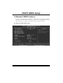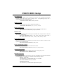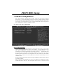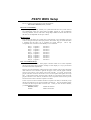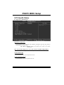
1
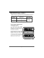
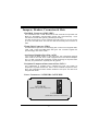
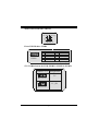
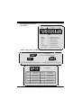
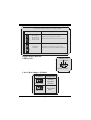
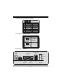
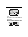
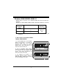
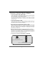
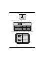
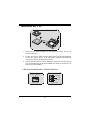
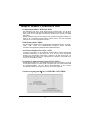
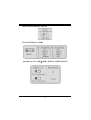
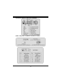
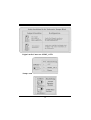
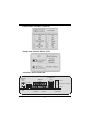
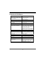
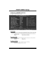
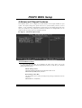
P C FC SF P44S FCC Statement and Copyright This equipment has been tested and found to comply with the limits of a Class B digital device, pursuant to Part 15 of the FCC Rules. These limits are designed to prov ide reasonable protection against harmf ul interference in a residential installation. This equipment generates, uses and can radiate radio f requency energy and, if not installed and used in accordance with the instructions, may cause harmful interf erence to radio communications. There is no guarantee that interf erence will not occur in a particular installation. The v endor makes no representations or warranties with respect to the contents here of and specially disclaims any implied warranties of merchantability or fitness f or any purpose. Further the vendor reserves the right to revise this publication and to make changes to the contents here of without obligation to notify any party beforehand. Duplication of this publication, in part or in whole is not allowed without f irst obtaining the v endor’s approval in writing. The content of this user’s is subject to be changed without notice and we will not be responsible for any mistakes f ound in this user’s manual. All the brand and product names are trademarks of their respective companies. i C Coonntteennttss ENGLISH.............................................................................................1 P4SFC Features...............................................................................................................................1 Package contents ...........................................................................................................................2 Layout of P4SFC .............................................................................................................................3 CPU Installation...............................................................................................................................4 DDR DIMM Modules: DDR1-2.......................................................................................................5 Jumpers, Head ers, Connectors & Slots ...................................................................................6 ESPAÑOL.......................................................................................... 11 Caracter ísticas del P4SFC..........................................................................................................11 Contenido del Paqu ete................................................................................................................12 Disposición del P4SFC ................................................................................................................13 Instalación del CPU ......................................................................................................................14 Módulos DDR DIMM: DDR1-2....................................................................................................15 Conectores, C abezales, Pu entes y Ranur as .........................................................................16 DEUTSCH .......................................................................................... 22 Merkmal e des P4SFC ...................................................................................................................22 Verpackung sinhalt ........................................................................................................................23 Layout von P4SFC ........................................................................................................................24 Installation d er CPU .....................................................................................................................25 DDR-DIMM-Modules: DDR1-2....................................................................................................26 Jumpers, Head ers, Connectors & Slots .................................................................................27 TROU BLE SHOOTING ....................................................................... 32 SOLUCIÓN DE PROBLEMAS ............................................................ 33 PROBLEMLÖSUNG........................................................................... 34 ii English P4SFC Features CPU ® Supports Intel Pentium 4 Socket 478 processor up to 3.06 GHz. Running at 533 MHz Front Side Bus frequency. Chipset North Bridge: SIS 651. South Bridge: SIS 962L. Main - Memory Supports up to 2 DDR devices. Supports 200/ 266/ 333 MHz (without ECC). The largest memory capacity is 2GB. Slots Three 32-bit PCI bus master slots. One AGP slot. On Board IDE Supports four IDE hard disk drives. Supports PIO Mode 4, Master Mode and Ultra DMA 33/ 66/ 100/ 133 Bus Master Mode. LAN - – VT6103 (optional) Dual Speed - 100/10 Mbps. Half and Full Duplex. Auto Negotiation: 10/ 100, Full/ Half Duplex. Audio AC97 2.2 interface. PC99 complaint. Supports 6 channels. On Board Peripherals Supports 360K, 720K, 1.2MB, 1.44MB and 2.88MB f loppy disk driv ers. Supports 1 serial port. Supports 1 VGA port. Supports 1 LAN port (optional). Supports 1 multi-mode parallel port. (SPP/EPP/ECP mode) Supports PS/2 mouse and PS/2 key board. Supports 1 v ertical audio port. Supports 4 rear USB2.0 ports and 2 front USB2.0 ports. 1 BIOS AWARD legal Bios. Supports APM1.2. Supports ACPI. Supports USB Function. Operating System Offers the highest perf ormance for Windows 98SE, Windows 2000, Windows Me, Windows XP, LINUX and SCO UNIX. Dimensions Micro ATX Form Factor: 20.3cm X 23.4cm (W X L). Package contents - HDD Cable X 1 FDD Cable X 1 Fully Setup Driv er CD X 1 USB Cable X 2 (Optional) Rear I/O Panel f or Micro-ATX Case X 1 (Optional) SPDIF Out Cable X1 (Optional) User’s Manual X1 2 Layout of P4SFC JKBMS1 JCFAN1 JUSBV2 KB & Mou se 1 1 JATXPWR2 JUSB1 Soc ket 478 USB JAT XPWR1 COM1 JC OM1 VGA1 DDR 1 DDR 2 Parallel Port JPR NT1 IDE 2 IDE1 ITE I/O BIOS JVGA1 USB & LAN SIS 651 1 JUSB V3 JUSB LAN2 JAUDI O 13 14 1 2 AGP1 JAUDIO1 L AN PHY JUSB V1 1 PCI1 2 10 1 9 BAT1 CODEC 2 1 JGAME 1 1 JC DIN2 1 1 SIS 962L JU SB 2 JCDIN1 16 15 PCI2 SPDIF_OUT1 24 JC I1 1 JWOL1 JSFAN1 1 1 JCM OS1 1 JPANEL1 2 FDD1 PC I3 3 23 1 CPU Installation CP U 1. Pull the lever sideway s away from the socket then raise the lever up to 90-degree angle. 2. Locate Pin A in the socket and lock for the white dot or cut edge in the CPU. Match Pin A with the white dot/cut edge then insert the CPU. 3. Press the lever down. Then Put the f an on the CPU and buckle it and put the f an’s power port into the JCFAN1, then to complete the installation. CPU/ S ystem Fan Headers: JCFAN1/ JS FAN1 12V S ense Ground 1 1 Se nse 12V Ground JCFAN1 JSFAN1 4 DDR DIMM Modules: DDR1-2 DRAM Access Time: 2.5V Unbuffered DDR 200/ 266/ 333 MHz Ty pe required. DRAM Ty pe: 64MB/ 128MB/ 256MB/ 512MB/ 1GB DIMM Module (184 pin) DIMM Socket Location DDR Module DDR 1 64MB/128MB/256MB/512MB/1GB *1 To tal Memory Size (MB) Max is 2GB 64MB/128MB/256MB/512MB/1GB *1 * The list shown abov e f or DRAM configuration is only f or reference. DDR 2 How to install a DIMM Module DDR DIMM Module 1. The DIMM socket has a “ Plastic Safety Tab”, and the DIMM memory module has an “Asymmetrical notch”, so the DIMM memory module can only fit into the slot in one direction. 2. Push the tabs out. Insert the DIMM memory modules into the socket at a 90-degree angle, then push down v ertically so that it will f it into the place. 3. The Mounting Holes and plastic tabs should f it over the edge and hold the DIMM memory modules in place. 5 Jumpers, Headers, Connectors & Slots Hard Disk Connectors: IDE1/ IDE2 The motherboard has a 32-bit Enhanced PCI IDE Controller that prov ides PIO Mode 0~4, Bus Master, and Ultra DMA / 33/ 66/ 100 / 133 functionality. It has two HDD connectors IDE1 (primary ) and IDE2 (secondary ). The IDE connectors can connect a master and a slave driv e, soy ou can connect up to four hard disk driv es. The first hard drive should alway s be connected to IDE1. Floppy Disk Connector: FDD1 The motherboard prov ides a standard floppy disk connector that supports 360K, 720K, 1.2M, 1.44M and 2.88M f loppy disk types. This connector supports the prov ided f loppy drive ribbon cables. Accelerated Graphics Port S lot: AGP1 Your monitor will attach directly to that v ideo card. This motherboard supports video cards f or PCI slots, but it is also equipped with an Accelerated Graphics Port. An AGP card will take adv antage of AGP technology for improved v ideo efficiency and performance, especially with 3D graphics. Peripheral Component Interconnect Slots: PCI1-3 This motherboard is equipped with 3 standard PCI slots. PCI stands f or Peripheral Component Interconnect, and it is a bus standard f or expansion cards, which has, supplanted the older ISA bus standard in most ports. This PCI slot is designated as 32 bits. Power Connectors: JATXPWR1/ J ATXPWR2 JATXPWR2 (ATX 12V Power Connector) JATXPWR1 ( ATX Main Pow er Connector) 6 Wake On LAN Header: JWO L1 Grou nd 5V_SB Wak e u p 1 JWOL1 Front USB Header: JUSB2 Pin Assignment Pin Assignment +5V +5V 1 2 Data (-) Data (-) 3 4 Data (+) Data (+) 5 6 Ground Ground 7 8 Key NA 9 10 2 1 JUSB2 5V/ 5 VS B Selection for US B: JUS BV1/ JUS BV2/ JUS BV3 JUSBV1/ 2/ 3 Assignment 1 5V Pin 1-2 on 1 5V_SB Pin 2-3 on 7 Front Panel Connector: JPAN EL1 PW R_LED SLP (+) (+) (-) ON/OFF IR 24 2 1 23 SPK SPK HLED RST IR (+) (-) HLED RST IR ==> Speaker Conn. ==> Hard Driver LED ==> Reset Button ==> Infrared Conn. SLP ==> Sleep Button PWR_LED ==> Power LED ON/ OFF ==> Power-on Button Audio S ubsystem: JAUDIO1/ JCDIN1/ JCDIN2 JAUDIO1 (Front Au dio He ader ) 1 2 1 1 JCDI N2 (CD-ROM Audio -In Hea der) 22 1 Pin 1 3 5 7 9 11 13 JCDIN1 (CD-ROM Audio -In Hea der) 14 13 Assignment Mic In Mic Power RT Line Out Reserved LFT Line Out RT Line In LFT Line In JAUDIO1 Pin 2 4 6 8 10 12 14 8 Assignment Ground Audio Power RT Line Out NC LFT Line Out RT Line In LFT Line In Fro nt Panel Audio Connector/ Jumper Block Jum per S etting 1 3 5 7 9 11 13 2 4 6 1 3 5 7 9 11 13 2 4 6 10 12 14 10 12 14 Configu ration Pin 5 and 6 Pin 9 and 10 Pin11 a nd 12 Pin13 and 14 A udio line out signals are route d to the back pane l audio line out c onnector. No jumper s installed A udio line out and mic in signa ls ar e a va ilable for front panel audio connec tors. Digital Audio Connector: S PDIF_OUT1 SP DIF _O UT 5V GND 1 SPDIF_O UT1 Clear CMOS Jumper: JCMOS1 JCMOS1 Assignment Normal Operation (default) 1 Pin 1-2 on 1 Clear CMOS Data Pin 2-3 on 9 Game Header: JGAME1 (Optional) 2 16 JGAME1 1 15 Pin Assignment Pin Assignment +5V +5V 1 2 GP 6 GP4 3 4 GP 2 GP0 5 6 Ground 7 MIDI-OUTR 8 9 10 Ground GP3 11 12 GP7 GP1 13 MIDI-INR 14 GP5 15 16 NC +5V Case Open Connector: JCI1 JCI1 Assignment Normal Operation (default) 1 No jumper installed 1 Case Open Pin 1-2 on Back Panel Connectors JUSBLAN2 JKBMS1 JPRNT1 Mouse PS/2 LAN Line In Parallel Port JUSB1 Speaker Out MIC In Keyboard PS/2 USB COM1 VGA1 JCOM1 JVGA1 10 USB JAUDIO Español Características del P4SFC CPU ® Soporta procesador Intel Pentium 4 Socket 478 de hasta 3.06 GHz. Corre a 533 MHz Front Side Bus. Chipset North Bridge: SIS 651. South Bridge: SIS 962L. Memoria Principal Soporta hasta 2 dispositivos DDR. Soporta 200/ 266/ 333 MHz (sin ECC). Capacidad máxima de memoria 2GB. Ranuras Tres ranuras de 32-bit PCI bus master. Una ranura AGP. IDE Onboard Soporta cuatro discos duros IDE. Soporta Modo PIO 4, Modo Master y Ultra DMA 33/ 66/ 100/ 133 Bus Modo Master. LAN - – VT6103 (opcional) Doble Velocidad - 100/10 Mbps. Half y Full Duplex. Auto Negociación: 10/ 100, Full/ Half Duplex. Audio Interface AC97 2.2. PC99 compatible. Soporta 6 canales. Periféricos Onboard Soporta disquetera de 360K, 720K, 1.2MB, 1.44MB y 2.88MB. Soporta 1 puerto serie. Soporta 1 puerto VGA. Soports 1 puerto LAN (opcional). Soporta 1 puerto paralelo multi-mode. (modo SPP/EPP/ECP) Soporta ratón PS/2 y teclado PS/2. Soporta 1 puerto de audio vertical. Soporta 4 puertos USB2.0 traseros y 2 puertos USB2.0 f rontales. 11 BIOS AWARD legal Bios. Soporta APM1.2. Soporta ACPI. Soporta f unción USB. Sistema Operativo Of rece el más alto funcionamiento en Windows 98SE, Windows 2000, Windows Me, Windows XP, LINUX y SCO UNIX. Dimensiones Factor de Forma Micro ATX: 20.3cm X 23.4cm (W X L). Contenido del Paquete - Cable HDD X 1 Cable FDD X 1 Configuración Completa del CD Driver X 1 Cable USB X 2 (Opcional) Panel Trasero I/O para carcasa Micro-ATX X 1 (Opcional) Cable SPDIF Out X 1 (Opcional) Manual del Usuario X 1 12 Disposición del P4SFC JKBMS1 JUSBV2 Teclado & Raton JCFAN1 1 1 JATXPWR2 JUSB1 So ck et 47 8 USB JATXPWR1 JPRNT1 DDR1 DDR2 V GA1 Puer to Paralelo COM 1 JCOM1 I DE2 IDE1 ITE I/O BIOS JVGA1 US B & LAN SIS 651 1 JUSBV3 JUSBLAN2 JAUDIO 13 14 1 2 AGP1 JAUDIO1 LAN PHY JUSBV1 1 PCI1 2 10 1 9 BAT1 COD EC JGAME1 2 1 1 SIS 962L JUSB2 JCDI N1 16 15 PCI2 SPDI F OUT1 24 JCI1 1 JCDIN2 1 1 JWOL1 JSFAN1 1 1 JCMOS1 JPANEL1 1 2 PCI3 FDD1 13 23 1 Instalación del CPU CP U 1. Tire de la palanca del lado del zócalo, luego levante la palanca hasta un ángulo de 90 grados. 2. Sitúe el contacto A del zócalo y busque el punto blanco o corte el borde en la CPU. Empareje el contacto A con el punto blanco/ corte del borde, luego inserte la CPU. 3. Presione la palanca para abajo. Ponga el ventilador en la CPU y abróchelo. Luego ponga el puerto de corriente del ventilador en el JCFAN1. Y ya habrá completado su instalación. CPU/ Cabezales del Sistema de Ventilación: JCFAN1/ JS FAN1 12V Sen se Tierra 1 Se nse 12V Tier ra 1 J CFAN1 JSFAN 1 14 Módulos DDR DIMM: DDR1-2 DRAM Tiempo de Acceso: 2.5V Unbuffered DDR 200/ 266/ 333 MHz Tipo requerido. DRAM Tipo: 64MB/ 128MB/ 256MB/ 512MB/ 1GB Módulo DIMM (184 contactos) Localización del Módulo DIMM Módulo DDR DDR 1 64MB/128MB/256MB/512MB/1GB *1 To tal del Tamaño de Memoria (MB) Máximo 2GB 64MB/128MB/256MB/512MB/1GB *1 * La lista de arriba para la configuración DRAM es solamente para ref erencia. DDR 2 Cómo instalar un módulo DIMM Módulo DDR DIMM 1. El zócalo DIMM tiene una lengüeta plástica de seguridad y el módulo de memoria DIMM tiene una muesca asimétrica, así el módulo de memoria DIMM puede caber solamente en la ranura de una sóla dirección. 2. Tire la lengüeta hacia af uera. Inserte los módulos de memoria DIMM en el zócalo a los 90 grados, luego empuje hacia abajo v erticalm ente de modo que encaje en el lugar. 3. Los agujeros de montaje y las lengüetas plásticas deben caber por sobre el borde y sostenga los módulos de memoria DIMM en el lugar. 15 Conectores, Cabezales, Puentes y Ranuras Conectores del Disco Duro: IDE1/ IDE2 La placa madre tiene un controlador de 32-bit PCI IDE que proporciona Modo PIO 0~4, Bus Master, y funcionalidad Ultra DMA 33/ 66/ 100/ 133. Tiene dos conectores HDD IDE1 (primario) y IDE2 (secundario). El conector IDE puede conectar a un master y un drive esclav o, así puede conectar hasta cuatro discos rígidos. El primer disco duro debe estar siempre conectado al IDE1. Conector para Disquete: FDD1 La placa madre proporciona un conector estándar del disquete (FDC) que soporta 360K, 720K, 1.2M, 1.44M y 2.88M tipos de disquete. Éste conector utiliza los cables de cinta proporcionados por el disquete. Ranura del Puerto Acelerado para Gráficos: AGP1 Su monitor se f ijará directamente a la tarjeta de v ideo. Ésta placa madre soporta tarjetas de v ideo para ranuras PCI, y también está equipado con un Puerto Acelerado para Gráf icos. Ésta tarjeta AGP tomará v entaja de la tecnología del AGP para el mejoramiento de la ef iciencia y funcionamiento del video, especialmente con gráficos 3D. Ranura de Interconexión del Componente Periférico: PCI1-3 Ésta placa madre está equipada con 3 ranuras estándar PCI. PCI es la sigla para Interconexión del Componente Periférico, y es un bus estándar para tarjetas de expansión en el que suplanta a la antigua bus estándar ISA, en su mayoría de las partes. Ésta ranura PCI está diseñado con 32 bits. Conectores de Corriente: JATXPWR1/ J ATXPWR2 JATXPWR2 (ATX 12V Conector de Corriente) JATXPWR1 (ATX Cone ctor de Corriente Principa l) 16 Cabezal Wake On LAN: J WOL1 Ti erra 5V_SB Wak e u p 1 JWOL1 Cabezal Frontal US B: JUS B2 2 1 Contactos Asignacion 1 +5V 3 Data (-) 5 Data (+) 7 Tierra 9 Key JUSB2 Contactos 2 4 6 8 10 Asignacion +5V Data (-) Data (+) Tierra NA 5V/ 5 VS B Selección para US B: JUS BV1/ JUSBV2/ JUS BV3 JUSBV1/ 2/ 3 Asignacion 1 5V Contactos 1-2 on 1 5V_SB Contactos 2- 3 on 17 Conector del Panel Frontal: JPANEL1 PW R_LED SLP (+) (+) (-) ON/OFF IR 24 23 2 1 SPK (+) (-) HLED RST IR SPK ==> Conector de Altavoz HLED ==> LED del Disco Duro RST ==> Boton de Reinicio IR ==> Conector Infrarojo SLP ==> Boton de Suspension PWR_LED ==> Corriente LED ON/ OFF ==> Boton de Encendido Subsistema de Audio: JAUDIO1/ JCDIN1/ JCDIN2 1 2 JAUDIO1 (Cabezal Fro ntal de Au dio) 1 JC DIN2 (C ab ezal d e Entrada de Aud io CD-R OM) 1 JC DIN1 (C ab ezal d e Entrada de Aud io CD-R OM) 18 22 1 Contactos 1 3 5 7 9 11 13 14 13 JAUDIO1 Asignacion Asignacion Contactos Tierra Entrada del MIC 2 Corriente de Audio Corriente del MIC 4 RT Salida de Linea RT Salida de Linea 6 Key Reservado 8 LFT Salida de Linea LFT Salida de Linea 10 12 RT Entrada de Linea RT Entrada de Linea LFT Entrada de Linea LFT Entrada de Linea 14 Con ect or d el Pa nel F ront al d e A ud io/ Ju mp er B lock Jumper Setti ng 1 3 5 7 9 11 13 1 3 5 7 9 11 13 Con fig ur acion 2 4 6 Conta cto 5 & 6 La se~na l de salida de line a de l Audio Conta cto 9 & 10 enc am ina al c one ctor de la salida de linea 10 Conta cto 11 & 12 del Audio ubicado e n e l panel tra ser o. 12 Conta cto 13 & 14 14 2 4 6 10 12 14 No jum per s insta lle d La se~na l de salida de line a de l Audio y la ~ l de l entra da de l m ic esta n disponible s sena desde e l cone ctor de Audio del pane l f ronta l. 19 Conector Digital de Audio: S PDIF_OUT1 SP DIF _O UT 5V GND 1 SPDIF_O UT1 Puente de Borrar CMOS : JCMOS1 Asignacion JCMOS1 Operacion Normal (Default) 1 Contacto 1-2 on 1 Borrar Datos CMOS Contacto 2-3 on Cabezal de Juego: JGAME1 (Opcional) 2 16 JGAME1 1 15 Contactos Asignacion Contactos Asignacion +5V +5V 1 2 GP 6 GP4 3 4 GP 2 GP0 5 6 GND 7 8 MIDI-OUTR 9 10 GP3 GND 11 12 GP7 GP1 13 14 MIDI-INR GP5 15 16 NC +5V 20 Conector de la Carcasa Abierta: JCI1 JCI1 Asignacion 1 Puente sin instalar Operacion Normal (default) 1 Carcasa Abierta Contacto 1-2 on Conector del Panel Trasero JUSBLAN2 JKBMS1 JPRNT1 PS/2 Mouse LAN Puerto Paralelo JUSB1 PS/2 Keyboard USB COM1 VGA1 JCOM1 JVGA1 21 Entrada de Linea Salida de Altavoz Entrada del MIC USB JAUDIO Deutsch Merkmale des P4SFC CPU ® Unterstützung f ür den Intel Pentium 4 Prozessor(Socket 478) bis zu 3.06 GHz. FSB 533 MHz . Chipsatz Northbridge: SIS 651. Southbridge: SIS 962L. Main - Memory Unterstützung für 2 DDR Geräte. Unterstützung für 200/ 266/ 333 MHz (ohne ECC). Die maximale Speichergröße ist 2GB. Slots Drei 32-Bit PCI-Bus-Master-Slots. Ein AGP-Slot. On-Board-IDE Unterstützung für vier IDE Diskettenlauf werke. Unterstützung für PIO Modus 4, Master Modus und Ultra DMA 33/ 66/ 100/ 133 Bus Master Modus. LAN - – VT6103 (optional) Dual Speed - 100/10 Mbps. Half - und Full-Duplex. Auto Negotiation: 10/ 100, Full/ Half Duplex. Audio AC97-2.2-Interf ace. PC99 kompatibel. Unterstützung für 6-Kanal. On-Board-Peripheriegeräte 1 Floppy -Port mit Unterstützung f ür 2 Diskettenlauf werke.(360KB, 720KB, 1.2MB, 1.44MB und 2.88MB). 1 serielle Schnittstelle. 1 VGA-Schnittstelle. 1 LAN-Schnittstelle. (optional) 1 parallele Schnittstelle mit Unterstützung f ür SPP/EPP/ECP -Modus Unterstützung für PS/2-Maus und PS/2-Tastatur. 1 v ertikale Audio-Sschnittstelle. 4 USB2.0-Ports auf der Rückwand und 2 USB2.0-Ports auf der Vorderseite. 22 BIOS Unterstützung für AWARD legal Bios. Unterstützung für APM1.2. Unterstützung für ACPI. Unterstützung für USB Function. Betriebsysteme Unterstützung f ür die am meisten verbreiteten Betriebsysteme wie Windows 98SE, Windows 2000, Windows ME, Windows XP, LINUX und SCO UNIX. Abmessungen Micro ATX Form-Factor: 20.3cm X 23.4cm (W X L). Verpackungsinhalt - HDD Kable X 1 FDD Kable X 1 Treiber CD für Installation X 1 USB Kable X 2 (optional) I/O-Rückwand für ATX Gehäuse X 1 (optional) SPDIF-Ausgang Kable X1 (optional) Benutzer Handbuch X 1 23 Layout von P4SFC JKBMS1 KB & Mou se JCFAN1 JUSBV2 1 1 JATXPWR2 JUSB1 Soc kel 478 USB JAT XPWR1 COM1 JCOM1 VGA1 DDR 1 DDR 2 Parallel Por t JPRNT1 IDE 2 IDE1 ITE I/O BIOS JVGA1 USB & LAN SIS 651 1 JUSBV3 JUSBLAN2 JAUDI O 13 14 1 2 AGP1 JAUDIO1 L AN PHY JUSBV1 1 PCI 1 2 10 1 9 BAT1 CODEC 2 1 JGAME 1 16 15 JU SB2 JCDIN1 1 SIS 962L PCI 2 SPDIF_OUT1 24 JCI1 1 JCDIN2 1 1 JW OL1 JSFAN1 1 1 JCM OS1 1 JPANEL1 2 FDD1 PCI3 24 23 1 Installation der CPU CP U 1. Ziehen Sie den Hebel seitwärts v on der Sockel und neigen Sie ihn um 90-Grad nach oben. 2. Suchen Sie Pin A im Sockel und den weißen Punkt oder die Abschnittkante in der CPU. Passen Sie Pin A mit dem weißen Punkt/der Abschnittkante zusammen und legen Sie danach die CPU ein. 3. Drücken Sie den Hebel nach unten. Befestigen Sie danach den Lüfter auf die CPU und schließen Sie die Stromschnittstelle des Lüfters an JCFAN1 an und beenden Sie die Installation. CPU/ S ystem Fan Headers: JCFAN1/ JS FAN1 12V Se nsor Masse 1 1 JSFAN1 Se nsor 12V Masse JCFAN1 25 DDR-DIMM-Modules: DDR1-2 DRAM Zugriffszeit: 2.5V unbuffer DDR 200/266/ 333 MHz. DRAM Ty pen: 64MB/ 128MB/ 256MB/ 512MB/ 1GB DIMM-Module (184 pin) DIMM- Sockel Standort DDR-Module DDR 1 64MB/128MB/256MB/512MB/1GB *1 Speichergröße (MB) maximal ist 2GB 64MB/128MB/256MB/512MB/1GB *1 * Die obergezeigt Liste f ür DRAM-Konf iguration ist nur als Referenz. DDR 2 Installation von DIMM-Modulen DDR-DIMM-Module 1. Es gibt eine Plastikklammer an beiden Enden der DIMM-Slot, und eine Passkerbe in der Mitte des Moduals. Deswegen passt das Dimm-Modual nur in einer Richtung. 2. Ziehen Sie die Plastikklammer aus. Setzen Sie das DIMM-Modual im 90-Grad-Winkel in den DIMM-Steckplatz und drücken es nach unten. 3. Schließen Sie die Plastikklammer, um das DiMM-Modul zu verriegeln. 26 Jumpers, Headers, Connectors & Slots Festplattenanschlüsse: IDE1 und ID E2 Das Mainboard hat einen 32-Bit Enhanced PCI IDE-Controller, der die Modi PIO0~4, Bus Master sowie die Ultra DMA/33/66/100/133- Funktion zur Verf ügung stellt. Dieser ist mit zweii HDD-Anschlüssen versehen IDE1 (primär) und IDE2 (sekundär). Die IDE-Anschlüsse können eine Master- und eine Slave-Festplatte verbinden, so dass bis zu 4 Festplatten angeschlossen werden können. Die erste Festplatte sollte immer an IDE1 angeschlossen werden. Diskettenanschluss: FDD1 Das Motherboard enthält einen standardmäßigen Diskettenanschluss, der 360K-, 720K-, 1.2M-, 1.44M- und 2.88M-Disketten unterstützt. Dieser Anschluss unterstützt die mitgelief erte Bandkabel des Diskettenlaufwerks. Accelerated Graphics Port S lot: AGP1 Ihr Monitor wird direkt an die Graf ikkarte angeschlossen. Dieses Motherboard unterstützt Graf ikkarten für PCI-Slots, aber es ist auch mit einem Accelerated Graphics Port ausgestattet. AGP-Karten v erwenden die AGP-Technologie, um die Wirksamkeit und Leistung von Videosignalen zu v erbessern, besonders wenn es sich um 3D-Grafiken handelt. Peripheral Component Interconnect Slots: PCI1-3 Dieses Motherboard ist mit 2 standardmäßigen PCI-Slots ausgestattet. PCI steht f ür Peripheral Component Interconnect und bezieht sich auf einem Busstandard f ür Erweiterungskarten, der den älteren ISA-Busstandard in den meisten Schnittstellen ersetzt hat. Dieser PCI-Slot ist f ür 32 bits vorgesehen. S tromversorgungsanschlü ssü: JATXPWR1/ J ATXPWR2 27 Wake On LAN Header: JWO L1 Front USB Header: JUSB2 Auswahl von 5V/ 5 VS B fü rUSB: JUSBV1/ JUS BV2JUS BV3 28 Anschlüsse auf der Vorderseite:JPANEL1 Audio S ubsystem: JAUDIO1/ JCDIN1/ JCDIN2 29 Digital Audio Connector: S PDIF_OUT1 Jumper zum Löschen des CMOS: JCMOS1 30 Game Header: JGAME1 (Optional) Jumper zum Gehäuse-Öffnen: JCI1 Anschlüsse auf der Rückwand JUSBLAN2 JK BMS1 JPRNT1 Maus PS/2 LAN Line In Parallel JUSB1 Lautsprecher-Ausgang MIC In Tastatur PS/2 USB COM1 VGA1 JCOM1 JVGA1 31 USB JAUDIO Trouble Shooting PROBABLE SOLUTION No power to the system at all Power light don’t * Make sure power cable is securely plugged in illuminate, fan inside power supply does not turn * Replace cable on. Indicator light on keyboard does not turn on * Contact technical support PROBABLE SOLUTION System inoperative. Keyboard lights are on, * Using even pressure on both ends of the power indicator lights are lit, hard drive is DIMM, press down firmly until the module snaps into place. spinning. PROBABLE SOLUTION System does not boot from hard disk drive, can * Check cable running from disk to disk be booted from CD-ROM drive. controller board. Make sure both ends are securely plugged in; check the drive type in the standard CMOS setup. * Backing up the hard drive is extremely important. All hard dis ks are capable o breaking down at any time. PROBABLE SOLUTION System only boots from CD-ROM. Hard disk can * Back up data and applications files. Reforma be read and applications can be used but the hard drive. Re-install applications and data using backup disks. booting from hard disk is impossible. PROBABLE SOLUTION Screen message says “Invalid Configuration” or * Review system’s equipment . Make sure “CMOS Failure.” correct information is in setup. PROBABLE SOLUTION Cannot boot system after installing second hard * Set master/slave jumpers correctly. drive. * Run SET UP program and select correct drive types. Call drive manufacturers for compatibility with other drives. 32 Solución de Problemas CAUSA PROB ABLE SOLUCIÓN No hay corriente en el sistema. La luz de * corriente no ilumina, ventilador dentro de la fuente de alimentación apagada. Indicador de * luz del teclado apagado. * Asegúrese que el cable de transmisión esté seguramente enchufado. Reemplace el cable. Contacte ayuda técnica. CAUSA PROBABLE SOLUCIÓN Sistema inoperativo. Luz del teclado encendido, * Presione los dos extremos del DIMM, presione luz de indicador de corriente iluminado, disco para abajo firmemente hasta que el módulo rígido está girando. encaje en el lugar. CAUSA PROBABLE SOLUCIÓN Sistema no arranca desde el disco rígido, puede * Controle el cable de ejecución desde el disco ser arrancado desde el CD-ROM drive. hasta el disco del controlador. Asegúrese de que ambos lados estén enchufados con seguridad; controle el tipo de disco en la configuración estándar CMOS. * Copiando el disco rígido es extremadamente importante. T odos los discos rígidos son capaces de dañarse en cualquier momento. CAUSA PROB ABLE SOLUCIÓN Sistema solamente arranca desde el CD-ROM. * Copie datos y documentos de aplicación Disco rígido puede leer y aplicaciones pueden Vuelva a formatear el disco rígido. Vuelva a ser usados pero el arranque desde el disco instalar las aplicaciones y datos usando e rígido es imposible. disco de copiado. CAUSA PROB ABLE SOLUCIÓN Mensaje de pantalla ”Invalid Configuration” o * Revise el equipo del sistema. Asegúrese de que la información configurada sea correcta. “CMOS Failure.” CAUSA PROB ABLE SOLUCIÓN No puede arrancar después de instalar el * Fije correctamente el puente master/esclavo. segundo disco rígido. * Ejecute el programa SET UP y seleccione e tipo de disco correcto. Llame a una manufacturación del disco para compatibilidad con otros discos. 33 Problemlösung MÖGLICHE URSACHE LÖSUNG Das System hat keine Spannungsversorgung. * Versichern Sie sich, dass das Stromkabel richtig Die Stromanzeige leuchtet nicht, der Lüfter im angebracht ist Inneren der Stromversorgung wird nicht * Ersetzen Sie das Stromkabel eingeschaltet. T astaturleuchten sind nicht an. * Wenden Sie sich an Ihre Kundendienststelle MÖGLICHE URSACHE LÖSUNG Das System funktioniert nicht. Die * Drücken Sie das D I MM-Modul bei gleichem T astaturleuchten sind an, die Stromanzeige Druck an beide Seiten, bis es einrastet. leuchtet, die Festplatte dreht sich. MÖGLICHE URSACHE LÖSUNG Das System wird von der Festplatte nicht * Überprüfen Sie das Kabel zwischen Festplatte hochgefahren, vom CD-ROM-Treiber aber ja. und Festplatten-Controller. Versichern Sie sich, dass beide Enden richtig angebrach sind; überprüfen Sie den Laufwerktyp in der standardmäßigen CMOS-Einrichtung. * Ein Backup der Festplatte ist sehr wichtig. Alle Festplatten können irgendwann beschädig werden. MÖGLICHE URSACHE LÖSUNG Das System wird nur von der CD-RO M * Machen Sie eine Sicherungskopie von allen hochgefahren. Die Festplatte wird gelesen und Daten und Anwendungsdateien. Formatieren die Anwendungen sind funktionsfähig, aber es Sie die Festplatte und reinstallieren Sie die ist nicht möglich, das System von der Festplatte Anwendungen und Daten mit Hilfe von Backup-Disks. zu starten. MÖGLICHE URSACHE LÖSUNG Auf dem Bildschirm erscheint die Meldung * Überprüfen Sie die Systemkomponenten und “Ungültige Konfiguration” oder “CMOS Fehler.” versichern Sie sich, das diese richtig eingerichtet sind. MÖGLICHE URSACHE LÖSUNG Das System kann nach der Installation einer * Setzen Sie die Master/Slave-Jumper richtig ein. zweiten Festplatte nicht hochgefahren werden. * Führen Sie das SET UP-Programm aus und wählen Sie die richtigen Laufwerktypen. Wenden Sie sich an den Laufwerkhersteller, um die Kompatibilität mit anderen Laufwerken zu überprüfen. 34 04/4/2003 35 P4SFC BIOS Setup BIOS Setup........................................................................................1 1 Main Menu..................................................................................................... 3 2 Standard CMOS Features .............................................................................. 6 3 Advanced BIOS Features............................................................................... 9 4 Advanced Chipset Features.......................................................................... 13 5 Integrated Peripherals .................................................................................. 15 6 Power Management Setup ........................................................................... 20 7 PnP/PCI Configurations ............................................................................... 24 8 PC Health Status .......................................................................................... 26 9 Frequency Control ....................................................................................... 28 i P4SFC BIOS Setup BIOS Setup Introduction This manual discussed Award™ Setup program built into the ROM BIOS. The Setup program allows users to modify the basic system configuration. This special information is then stored in battery-backed RAM so that it retains the Setup information when the power is turned off. The Award BIOS™ installed in your computer system’s ROM (Read Only Memory) is a custom version of an industry standard BIOS. This means that it supports Intel Pentium ® 4 processor input/output system. The BIOS provides critical low-level support for standard devices such as disk drives and serial and parallel ports. Adding important has customized the Award BIOS™, but nonstandard, features such as virus and password protection as well as special support for detailed fine-tuning of the chipset controlling the entire system. The rest of this manual is intended to guide you through the process of configuring your system using Setup. Plug and Play Support These AWARD BIOS supports the Plug and Play Version 1.0A specification. ESCD (Extended System Configuration Data) write is supported. EPA Green PC Support This AWARD BIOS supports Version 1.03 of the EPA Green PC specification. APM Support These AWARD BIOS supports Version 1.1&1.2 of the Advanced Power Management (APM) specification. Power management features are implemented via the System Management Interrupt (SMI). Sleep and Suspend power management modes are supported. Power to the hard disk drives and video monitors can be managed by this AWARD BIOS. 1 P4SFC BIOS Setup PCI Bus Support This AWARD BIOS also supports Version 2.1 of the Intel PCI (Peripheral Component Interconnect) local bus specification. DRAM Support DDR SDRAM (Double Data Rate Synchronous DRAM) are supported. Supported CPUs This AWARD BIOS supports the Intel Pentium ® 4 CPU. Using Setup In general, you use the arrow keys to highlight items, press <Enter> to select, use the <PgUp> and <PgDn> keys to change entries, press <F1> for help and press <Esc> to quit. The following table provides more detail about how to navigate in the Setup program by using the keyboard. Keystroke Up arrow Down arrow Left arrow Right arrow Move Enter PgUp key PgDn key + Key - Key Esc key F1 key F5 key F7 key F10 key Function Move to previous item Move to next item Move to the item on the left (menu bar) Move to the item on the right (menu bar) Move to the item you desired Increase the numeric value or make changes Decrease the numeric value or make changes Increase the numeric value or make changes Decrease the numeric value or make changes Main Menu – Quit and not save changes into CMOS Status Page Setup Menu and Option Page Setup Menu – E xit Current page and return to Main Menu General help on Setup navigation keys Load previous values from CMOS Load the optimized defaults Save all the CMOS changes and exit 2 P4SFC BIOS Setup 1 Main Menu Once you enter Award BIOS™ CMOS Setup Utility, the Main Menu will appear on the screen. The Main Menu allows you to select from several setup functions. Use the arrow keys to select among the items and press <Enter> to accept and enter the sub-menu. !! WARNING !! The information about BIOS defaults on manual (Figure 1,2,3,4,5,6,7,8,9) is just for reference, please refer to the BIOS installed on board, for update information. Figure 1. Main Menu Standard CMOS Features This submenu contains industry standard configurable options. Advanced BIOS Features This submenu allows you to configure enhanced features of the BIOS. Advanced Chipset Features This submenu allows you to configure special chipset features. 3 P4SFC BIOS Setup Integrated Peripherals This submenu allows you to configure certain IDE hard drive options and Programmed Input/ Output features. Power Management Setup This submenu allows you to configure the power management features. PnP/PCI Configurations This submenu allows you to configure certain “Plug and Play” and PCI options. PC Health Status This submenu allows you to monitor the hardware of your system. Frequency Control This submenu allows you to change CPU Vcore Voltage and CPU/PCI clock. (However, this function is strongly recommended not to use. Not properly change the voltage and clock may cause CPU or M/B damage!) Load Optimized Defaults This selection allows you to reload the BIOS when the system is having problems particularly with the boot sequence. These configurations are factory settings optimized for this system. A confirmation message will be displayed before defaults are set. Set Password Setting the password will prohibit everyone except the supervisor from making changes using the CMOS Setup Utility. You will be prompted with to enter a password. 4 P4SFC BIOS Setup Save & Exit Setup Save all configuration changes to CMOS(memory) and exit setup. Confirmation message will be displayed before proceeding. Exit Without Saving Abandon all changes made during the current session and exit setup. message will be displayed before proceeding. Upgrade BIOS This submenu allows you to upgrade bios. 5 confirmation P4SFC BIOS Setup 2 Standard CMOS Features The items in Standard CMOS Setup Menu are divided into 10 categories. Each category includes no, one or more than one setup items. Use the arrow keys to highlight the item and then use the<PgUp> or <PgDn> keys to select the value you want in each item. Figure 2. Standard CMOS Setup 6 P4SFC BIOS Setup Main Menu Selections This table shows the selections that you can make on the Main Menu. Item Options Date mm : dd : yy Set the system date. Note that the ‘Day’ automatically changes when you set the date. Time hh : mm : ss Set the clock. IDE Primary Master Options are in its sub menu. Press <Enter> to enter the sub menu of detailed options IDE Primary Slave Options are in its sub menu. Press <Enter> to enter the sub menu of detailed options. IDE Secondary Master Options are in its sub menu. Press <Enter> to enter the sub menu of detailed options. IDE Secondary Slave Options are in its sub menu. Press <Enter> to enter the sub menu of detailed options. Drive A 360K, 5.25 in Drive B 1.2M, 5.25 in Select the type of floppy disk drive installed in your system. 720K, 3.5 in Description system internal 1.44M, 3.5 in 2.88M, 3.5 in None Video EGA/VGA CGA 40 CGA 80 MONO 7 Select the default device. video P4SFC BIOS Setup Item Halt On Options Description All Errors Select the situation in which No Errors you want the BIOS to stop All, but Keyboard All, but Diskette the POST process and notify you. All, but Disk/ Key Base Memory N/A Displays the amount of conventional memory detected during boot up. Extended Memory N/A Displays the amount of extended memory detected during boot up. Total Memory N/A Displays the total memory available in the system. 8 P4SFC BIOS Setup 3 Advanced BIOS Features Figure 3. Advanced BIOS Setup Virus Warning This option allows you to choose the Virus Warning feature that is used to protect the IDE Hard Disk boot sector. If this function is enabled and an attempt is made to write to the boot sector, BIOS will display a warning message on the screen and sound an alarm beep. Disabled (default) Virus protection is disabled. Enabled Virus protection is activated. CPU L1 & L2 Cache The option allows you to enable/ disable CPU Cache to speed up the system performance. Enabled (default) Enable cache. Disabled Disable cache. CPU Hyper-Threading This option allows you to enable or disabled CPU Hyper-Threading. The Choices: Enabled (Default), Disabled. 9 P4SFC BIOS Setup CPU L2 Cache ECC Checking This item allows you to enable/disable CPU L2 Cache ECC Checking. The Choices: Enabled (default), Disabled. Quick Power On Self Test Enabling this option will cause an abridged version of the Power On Self-Test (POST) to execute after you power up the computer. Enabled (default) Enable quick POST. Disabled Normal POST. First /Second/Third/ Boot Other Device These BIOS attempts to load the operating system from the devices in the sequence selected in these items. The Choices: Floppy, LS120, HDD-0, SCSI, CDROM, HDD-1, HDD-2, HDD-3, ZIP100, LAN, HPT370, Enabled, Disabled. Swap Floppy Drive For systems with two floppy drives, this option allows you to swap logical drive assignments. The Choices: Enabled, Disabled (default). Boot Up Floppy Seek Enabling this option will test the floppy drives to determine if they have 40 or 80 tracks. Disabling this option reduces the time it takes to boot-up. The Choices: Enabled (default), Disabled. Boot Up NumLock Status Selects the NumLock. State after power on. On (default) Numpad is number keys. Off Numpad is arrow keys. Gate A20 Option Select if chipset or keyboard controller should control Gate A20. Normal A pin in the keyboard controller controls Gate A20. Fast (default) Lets chipset control Gate A20. Typematic Rate Setting When a key is held down, the keystroke will repeat at a rate determined by the keyboard controller. When enabled, the typematic rate and typematic delay can be configured. Disabled (default) Enabled 10 P4SFC BIOS Setup Typematic Rate (Chars/Sec) Sets the rate at which a keystroke is repeated when you hold the key down. The Choices: 6 (default), 8,10,12,15,20,24,30. Typematic Delay (Msec) Sets the delay time after the key is held down before it begins to repeat the keystroke. The Choices: 250 (default), 500,750,1000. Security Option This option will enable only individuals with passwords to bring the system online and/or to use the CMOS Setup Utility. System A password is required for the system to boot and is also required to access the Setup Utility. Setup (default) A password is required to access the Setup Utility only. This will only apply if passwords are set from the Setup main menu. APIC Mode This option allows you to enable or disable the APIC (Advanced Programmable Interrupt Control). The Choices: Enabled (default), Disabled. MPS Version Control For OS The BIOS supports version 1.1 and 1.4 of the Intel Multi-Processor Specification. Select version supported by the operation system running on this computer. The Choices: 1.4 (default), 1.1. OS Select For DRAM > 64MB A choice other than Non-OS2 is only used for OS2 systems with memory exceeding 64MB. The Choices: Non-OS2 (default), OS2. HDD S.M.A.R.T. Capability This item allows you to enable/disable the S.M.A.R.T. function of the hard disk. The Choices: Disabled (default), Enabled. Report No FDD For WIN 95 Whether report no FDD for WIN 95 or not. The Choices: No (default), Yes. Video BIOS Shadow Determines whether video BIOS will be copied to RAM for faster execution. Enabled (default) Optional ROM is enabled. Disabled Optional ROM is disabled. 11 P4SFC BIOS Setup Summary Screen Show This item allows you to enable/ disable display the Summary Screen Show. The Choices: Disabled (default), Enabled. 12 P4SFC BIOS Setup 4 Advanced Chipset Features This submenu allows you to configure the specific features of the chipset installed on your system. This chipset manage bus speeds and access to system memory resources, such as DRAM. It also coordinates communications with the PCI bus. The default settings that came with your system have been optimized and therefore should not be changed unless you are suspicious that the settings have been changed incorrectly. Figure 4. Advanced Chipset Setup Advanced DRAM Control 1 To control the DDR SDRAM. If you highlight the literal “Press Enter” next to the “Advanced DRAM Control” label and then press the enter key, it will take you a submenu with the following options: DRAM Timing Control This item determines DRAM clock/ timing follow SPD or not. The Choices: By SPD(default), Manual. RAS Precharge Time (tRP) This items allows you to specify the delay from precharge command to activate command. The Choices: 2T, 3T (default). 13 P4SFC BIOS Setup RAS Active Time (tRAS) This items allows you to specify the minimum bank active time. The Choices: 6T (default), 5T. RAS to CAS Delay (tRCD) Use this item to specify the delay from the activation of a bank to the time that a read or write command is accepted. The Choices: 2T, 3T (default). CAS Latency Setting When synchronous DRAM is installed, the number of clock cycles of CAS latency depends on the DRAM timing. The Choices: By SPD (default), 2T, 2.5T, 3T. DRAM Addr/ Cmd Rate The Choices: Auto (default), 1T, 2T. Prefetch Caching This item allows you enable/disable Prefetch Caching. The Choices: Enabled, Disabled (default). Memory Hole at 15M-16M When enabled, you can reserve an area of system memory for ISA adapter ROM. When this area is reserved , it cannot be cached. Refer to the user documentation of the peripheral you are installing for more information. The Choices: Disabled (default), Enabled. AGP Aperture Size Select the size of the Accelerated Graphics Port (AGP) aperture. The aperture is a portion of the PCI memory address range dedicated for graphics memory address space. Host cycles that hit the aperture range are forwarded to the AGP without any translation. The Choices: 4M, 8M,16M, 32M, 64M (default), 128M, 256M. Graphic Window WR Combin This item allows you enable/disable Graphic Window write-combine. The Choices: Enabled, Disabled (default). 14 P4SFC BIOS Setup 5 Integrated Peripherals Figure 5. Integrated Peripherals SIS OnChip IDE Device If you highlight the literal “Press Enter” next to the “SIS OnChip IDE Device” label and then press the enter key, it will take you a submenu with the following options: Internal PCI/IDE This item allows you select Internal PCI/IDE. The Choices: Both (default), Disabled, Primary, Secondary. IDE Primary / Secondary Master / Slave PIO The IDE PIO (Programmed Input / Output) fields let you set a PIO mode (0-4) for each of the IDE devices that the onboard IDE interface supports. Modes 0 through 4 provide successively increased performance. In Auto mode, the system automatically determines the best mode for each device. The Choices: Auto (default), Mode0, Mode1, Mode2, Mode3, Mode4. Primary / Secondary Master / Slave UltraUDMA Ultra DMA/133 functionality can be implemented if it is supported by the IDE hard drives in your system. As well, your operating environment requires a DMA driver (Windows 95 OSR2 or a third party IDE bus master driver). If your hard drive and your system software both support Ultra DMA/133, select Auto to enable BIOS support. The Choices: Auto (default), Disabled. 15 P4SFC BIOS Setup IDE Burst Mode This item allows you enable/disable IDE Burst Mode. The Choices: Enabled (default), Disabled. SIS OnChip PCI Device If you highlight the literal “Press Enter” next to the “SIS OnChip PCI Device” label and then press the enter key, it will take you a submenu with the following options: SIS USB Controller This option allows you to control SIS USB Controlller. The Choices: Enabled (default), Disabled. USB Ports Number This option allows you to control USB Ports Number. The Choices: 6 (default), 5, 4, 3. USB 2.0 Supports This option allows you to enabled or disabled USB2.0 Supports. The Choices: Disabled, Enabled (default). USB Keyboard Support Enables support for USB attached keyboards. The Choices: Disabled (default), Enabled. SIS AC97 Audio This option allows you to control the onboard AC97 Audio. The Choices: Auto (default), Disabled. SIS S/W Modem This option allows you to control the onboard S/W Modem. The Choices: Auto (default), Disabled. SIS 10/100M ETHERNET This option allows you to control the 10/100M Ethernet. The Choices: Auto (default), Disabled. SIS MAC Address Input Onboard SuperIO Device If you highlight the literal “Press Enter” next to the “Onboard Super IO Device” label and then press the enter key, it will take you a submenu with the following options: Onboard FDC Controller Select Enabled if your system has a floppy disk controller (FDC) installed on the system board and you wish to use it. If install and FDC or the system has no floppy drive, select Disabled in this field. The Choices: Enabled (default), Disabled. 16 P4SFC BIOS Setup Onboard Serial Port 1 Select an address and corresponding interrupt for the first and second serial ports. The Choices: Disabled, 3F8/IRQ4 (default), 2F8/IRQ3, 3E8/IRQ4, 2E8/IRQ3, Auto. Onboard Serial Port 2 Select an address and corresponding interrupt for the first and second serial ports. The Choices: Disabled (default), 2F8/IRQ3, 3F8/IRQ4, 3E8/IRQ4, 2E8/IRQ3, Auto. UART Mode Select This item allows you to determine which Infra Red (IR) function of onboard I/O chip. The Choices: Normal, AS KIR, IrDA (default). UR2 Duplex Mode Select the value required by the IR device connected to the IR port. Full-duplex mode permits simultaneous two-direction transmission. Half-duplex mode permits transmission in one direction only at a time. The Choices: Half (default), Full. Onboard Parallel Port This item allows you to determine access onboard parallel port controller with which I/O Address. The Choices: 378/IRQ7 (default), 278/IRQ5, 3BC/IRQ7, Disabled. Parallel Port Mode The default value is SPP. SPP(default) EPP ECP ECP+EPP Using Parallel port as Standard Printer Port. Using Parallel Port as Enhanced Parallel Port. Using Parallel port as Extended Capabilities Port. Using Parallel port as ECP & EPP mode. ECP Mode Use DMA Select a DMA Channel for the port. The Choices: 3 (default), 1. Game Port Address Game Port I/O Address. The Choices: 201 (default), 209, Disabled. Midi Port Address Midi Port Base I/O Address. The Choices: 330 (default),300, 290, Disabled. 17 P4SFC BIOS Setup Midi Port IRQ This determines the IRQ in which the Midi Port can use. The Choices: 5, 10 (default). IDE HDD Block Mode Block mode is otherwise known as block transfer, multiple commands, or multiple sector read/write. Select the “Enabled” option if your IDE hard drive supports block mode (most new drives do). The system will automatically determine the optimal number of blocks to read and write per sector. The Choices: Enabled (default), Disabled. Init Display First With systems that have multiple video cards, this option determines whether the primary display uses a PCI Slot or an AGP Slot. The Choices: PCI Slot (default), AGP. AGP Auto Calibration This item allows you enable/disable AGP Auto Calibration. The Choices: Enabled (default), Disabled. System Share Memory Size This item allows you to select the system share memory size. The Choices: 32MB (default), 64MB, 16MB, 8MB, 4MB. IDECH0/1 Access Interface This item allows you to select the IDECH0/1 Access Interface. The Choices: EDB Bus (default), PCI Bus. USB0 Access Interface This item allows you select the USB0 Access Interface. The Choices: EDB Bus (default), PCI Bus. USB1 Access Interface This item allows you select the USB1 Access Interface. The Choices: EDB Bus (default), PCI Bus. USB2 Access Interface This item allows you select the USB2 Access Interface. The Choices: EDB Bus (default), PCI Bus. 18 P4SFC BIOS Setup USB2.0 Access Interface This item allows you select the USB2.0 Access Interface. The Choices: EDB Bus (default), PCI Bus. MAC Access Interface This item allows you select the MAC Access Interface. The Choices: Embedded Bus (default), PCI Bus. Audio Access Interface This item allows you select the Audio Access Interface The Choices: Embedded Bus (default), PCI Bus. 19 P4SFC BIOS Setup 6 Power Management Setup The Power Management Setup Menu allows you to configure your system to utilize energy conservation and power up/power down features. Figure 6. Power Management Setup ACPI function This item displays the status of the Advanced Configuration and Power Management (ACPI). The Choices: Enabled (default), Disabled. ACPI Suspend Type The item allows you to select the suspend type under the ACPI operating system. The Choices: S1 (POS) (default) Power on Suspend S3 (STR) Suspend to RAM S1 & S3 POS+STR Power Management This category allows you to select the type (or degree) of power saving and is directly related to the following modes: 1.HDD Power Down. 20 P4SFC BIOS Setup 2.Suspend Mode. There are four options of Power Management, three of which have fixed mode settings Min. Power Saving Minimum power management. Suspend Mode = 1 hr. Max. Power Saving Maximum power management only available for sl CPU’s. Suspend Mode = 1 min. User Defined (default) Allows you to set each mode individually. When not disabled, each of the ranges are from 1 min. to 1 hr. Suspend Mode The item allows you to select the suspend type under ACPI operating system. The Choices: Disabled (default), 1 Min, 2 Min, 4 Min, 6 Min, 8 Min, 20 Min, 30 Min, 40 Min, 1 Hour. Video Off Option This field determines when to activate the video off feature for monitor power management. The Choices: Suspend→ Off, Always on, Susp, StbyÆ Off (Default), All modesÆ Off. Video Off Method This option determines the manner in which the monitor is goes blank. V/H SYNC+Blank This selection will cause the system to turn off the vertical and horizontal synchronization ports and write blanks to the video buffer. Blank Screen This option only writes blanks to the video buffer. DPMS Supported (default) Initial display power management signaling. 21 P4SFC BIOS Setup Switch Function You can choose whether or not to permit your system or enter complete suspend mode. Suspend mode offers greater power savings, with a correspondingly longer with a correspondingly longer awakening period. The Choices: Break/ Wake (default), Disabled. Modem Use IRQ This determines the IRQ, which can be applied in MODEM use. The Choices: Auto (default), 3, 4, 5, 7, 9, 10, 11, NA. Hot Key Function As This item allows you select Hot Key Function As Power Off (Ctrl-Alt-Backspace). The Choices: Power Off (default), Suspend, Disabled. HDD Off After After a selected period of drive inactivity, the hard disk drive will power down while all other devices remain active. The Choices: Disabled (default), 1 Min, 2 Min, 3 Min, 4 Min, 5 Min, 6 Min, 7 Min, 8 Min, 9 Min, 10 Min, 11 Min, 12 Min, 13 Min, 14 Min, 15 Min. Power Button Override When you select Delay 4 sec, pressing the power button for more than 4 seconds forces the system to enter the Soft-Off state. The Choices: Instant Off (default), Delay 4 Sec. Power State Resume Control This item allows you to select Power State Resume Control. The Choices: Always off (default), Always on, Keep Pre-State. Chassis Open Warning This item allows you to enable or disable chassis open warning beep sound. The Choices: Enabled, Disabled (Default). PM Wake Up Events If you highlight the literal “Press Enter” next to the “PM Wake Up Events” label and then press the enter key, it will take you a submenu with the following options: IRQ [3-7, 9-15], NMI This item allows you enable/disable IRQ [3-7,9-15] NMI. The Choices: Enabled (default), Disabled. IRQ 8 Break Suspend This item allows you enable/disable IRQ8 Break Suspend. 22 P4SFC BIOS Setup The Choices: Disabled (default), Enabled. RING/ WOL Power Up Control This item allows you to control the RING Power Up. The Choices: Enabled, Disabled (default). MACPME Power Up Control This item allows you to control the MACPME Power Up. The Choices: Enabled, Disabled (default). PCIPME Power Up Control This item allows you to control the PCIPME Power Up. The Choices: Enabled, Disabled (default). Power Up by Alarm When you select Enabled, fields appear that let you set the alarm that returns the system to Full On state. The Choices: Disabled (default), Enabled. Month Alarm Select a month (1-12) or NA if you want the alarm active during all months Day of Month Alarm Select a date in the month. Select 0 if you prefer to set a weekly alarm. Time (hh:mm:ss) Alarm Set the time you want the alarm to go off on the days when it is activated. Reload Global Timer Events Reload Global Timer Events are I/O events whose occurrence can prevent the system from entering a power saving mode or can awaken the system from such a mode. In effect, the system remains alert for anything, which occurs to a device, which is configured as Enabled, even when the system is in a power down mode. Primary IDE Disabled (default), Enabled. Secondary IDE Disabled (default), Enabled. FDD, COM, LPT Port Disabled (default), Enabled. PCI, PIRQ[A-D]# Disabled (default), Enabled. Delay Prior to Thermal Set this item to enable the CPU Thermal function to engage after a specified time. The Choices: None (default), 1Min, 2Min, 4Min, 8Min, 16Min, 32Min, 64Min. 23 P4SFC BIOS Setup 7 PnP/PCI Configurations This section describes configuring the PCI bus system. PCI, or Personal Computer Interconnect, is a system which allows I/O devices to operate at speeds nearing the speed of the CPU itself uses when communicating with its own special components. This section covers some very technical items and it is strongly recommended that only experienced users should make any changes to the default settings. Figure 7. PnP/PCI Configurations Reset Configuration Data The system BIOS supports the PnP feature which requires the system to record which resources are assigned and protects resources from conflict. Every peripheral device has a node, which is called ESCD. This node records which resources are assigned to it. The system needs to record and update ESCD to the memory locations. These locations (4K) are reserved in the system BIOS. If the Disabled (default) option is chosen, the system‘s ESCD will update only when the new configuration varies from the last one. If the Enabled option is chosen, the system is forced to update ESCDs and then is automatically set to the “Disabled” mode. The above settings will be shown on the screen only if “Manual” is chosen for the resources controlled by function. Legacy is the term, which signifies that a resource is assigned to the ISA Bus and provides non-PnP ISA add-on cards. PCI / ISA PnP signifies that a resource is assigned to the PCI 24 P4SFC BIOS Setup Bus or provides for ISA PnP add-on cards and peripherals. The Choices: Disabled (default), Enabled. Resources Controlled By By Choosing “Auto(ESCD)” (default), the system BIOS will detect the system resources and automatically assign the relative IRQ and DMA channel for each peripheral.By Choosing “Manual”, the user will need to assign IRQ & DMA for add-on cards. Be sure that there are no IRQ/DMA and I/O port conflicts. IRQ Resources This submenu will allow you to assign each system interrupt a type, depending on the type of device using the interrupt. When you press the “Press Enter” tag, you will be directed to a submenu that will allow you to configure the system interrupts. This is only configurable when “Resources Controlled By” is set to “Manual”. IRQ-3 IRQ-4 IRQ-5 IRQ-7 IRQ-9 IRQ-10 IRQ-11 IRQ-12 IRQ-14 IRQ-15 assigned to assigned to assigned to assigned to assigned to assigned to assigned to assigned to assigned to assigned to PCI Device PCI Device PCI Device PCI Device PCI Device PCI Device PCI Device PCI Device PCI Device PCI Device PCI / VGA Palette Snoop Choose Disabled or Enabled. Some graphic controllers which are not VGA compatible take the output from a VGA controller and map it to their display as a way to provide boot information and VGA compatibility. However, the color information coming from the VGA controller is drawn from the palette table inside the VGA controller to generate the proper colors, and the graphic controller needs to know what is in the palette of the VGA controller. To do this, the non-VGA graphic controller watches for the Write access to the VGA palette and registers the snoop data. In PCI based systems, where the VGA controller is on the PCI bus and a non-VGA graphic controller is on an ISA bus, the Write Access to the palette will not show up on the ISA bus if the PCI VGA controller responds to the Write. In this case, the PCI VGA controller should not respond to the Write, it should only snoop the data and permit the access to be forwarded to the ISA bus. The non-VGA ISA graphic controller can then snoop the data on the ISA bus. Unless you have the above situation, you should disable this option. Disabled (default) Disables the function. Enabled Enables the function. 25 P4SFC BIOS Setup 8 PC Health Status Figure 8. PC Health Status Shutdown Temperature This item allows you to set up the CPU shutdown Temperature. This item only effective under Windows 98 ACPI mode. The Choices: Disabled (default), 60O C/140O F, 65O C/149OF, 70O C/158OF, 75O C/167OF. CPU Vcore/AGP Voltage/+3.3V/+5V/+12V/-12V/-5V/ 5V(SB) Voltage Battery Detect the system’s voltage status automatically. Current CPU Temp This field displays the current temperature of CPU. Current CPUFAN Speed This field displays the current speed of CPU fan. 26 P4SFC BIOS Setup Current SYS FAN Speed This field displays the current speed SYSTEM fan. Show H/W Monitor in POST If your computer contains a monitoring system, it will show PC health status during POST stage. The Choices: Enabled (Default), Disabled. 27 P4SFC BIOS Setup 9 Frequency Control Figure 9. Frequency Control CPU Clock Ratio This item allows you to select the CPU Ratio. The Choices: 0X (default). CPU Voltage This item allows you to select CPU Voltage Regulator. The Choices: 2.5V (default), 2.6V, 2.7V, 2.8V. DDR Voltage This item allows you to select DDR Voltage Regulator. The Choices: 2.5V (Default), 2.6, 2.7, 2.8. Auto Detect DIMM/ PCI Clk This item allows you to enable / disable auto Detect PCI Clock. The Choices: Enabled (default), Disabled. 28 P4SFC BIOS Setup Spread Spectrum This item allows you to enable/disable the Spread Spectrum function. The Choices: Enabled (default), Disabled. CPU Frequency This item allows you to control CPU Frequency. The Choices: Default (default), 100MHz, 133MHz. DRAM Frequency This item allows you to control DRAM Frequency. The Choices: By SPD (default), 200MHz, 266MHz, 333MHz. If unfortunately, the system’s frequency that you are selected is not functioning, there are two methods of booting-up the system. Method 1: Clear the CMOS data by setting the JCMOS1 ((2-3) closed)) as “ON” status. All the CMOS data will be loaded as defaults setting. Method 2: Press the <Insert> key and Power button simultaneously, after that keep-on pressing the <Insert> key until the power-on screen showed. This action will boot-up the system according to FSB of the processor. 29