1
,VVXH%
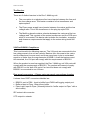
RS232 port pin outs.
PABX port.
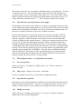
This port is the input to the buffer. It is set as a DTE by the internal links JP4 being set
‘side to side’ Note that +12V is presented on pin 25.
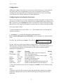
:LULQJRIWKHFRQQHFWRUWKDWFRQQHFWVWRWKHEXIIHULQSXWSRUW
3LQ 6LJQDO
'LUHFWLRQ
6DIHW\JURXQG
5[GDWD
2XWRIXQLW
7[GDWD
,QWRXQLW
&76
2XWRIXQLW
576
,QWRXQLW
6LJQDOJURXQG
9
2XWRIXQLW
Note- Auxiliary input ports if present are also linked as DTE. There are no DTE/DCE
configuration links for these ports.
Buffer output Port and buffer set up.
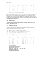
This port is normally linked to the Piper input by a ribbon cable (wired straight
through) on the back panel. It is set as a DTE by the internal links JP7 being set ‘side
to side’.
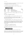
:LULQJRIWKHFRQQHFWRUWKDWFRQQHFWVWRWKHEXIIHURXWSXWSRUW
3LQ 6LJQDO
'LUHFWLRQ
6DIHW\JURXQG
7[GDWD
2XWRIXQLW
5[ GDWD
,QWRXQLW
576
2XWRIXQLW
&76
,QWRXQLW
6LJQDOJURXQG
'&'
,QWRXQLW
'75
2XWRIXQLW
9
2XWRIXQLW
The buffer can be configured through this port using ‘star’ commands described later.
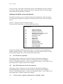
To configure the buffer –
x
x
Unplug the link cable on the back of the unit and plug a terminal set for 9600
baud, 8, N, 1 into the buffer output port (lower) connector.
Type *H to see the command summary and enter *W to see the current settings.
Piper input port and set up.
Piper, the V24 to ethernet converter, can be configured by connecting to the upper of
the two connectors normally linked by ribbon cable. This port is wired as DCE. For
full instructions on Piper see the ‘Piper User Guide’ at
KWWSZZZPXWHNFRXNGRZQORDGVKWP