1
,VVXH%
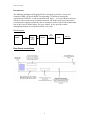
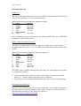
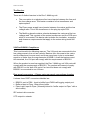
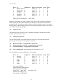
:LULQJRIWKHFRQQHFWRUWKDWFRQQHFWVWRWKH3LSHULQSXWSRUW
3LQ 6LJQDO
'LUHFWLRQ
6DIHW\JURXQG
7[GDWD
,QWRXQLW
5[GDWD
2XWRIXQLW
576
,QWRXQLW
&76
2XWRIXQLW
6LJQDOJURXQG
'&'
2XWRIXQLW
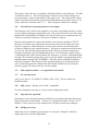
The important set up information for Piper used in a Combo Multilog is briefly
described here –
x
x
x
x
x
x
Unplug the link cable on the back of the unit and plug a terminal set for 9600
baud, 8, N, 1 into the Piper input port (upper) connector.
Type ++++ to enter Piper command mode.
Main menu item 2 allows a unit to be set up. Enter the factory default name Piper,
or the unit’s IP number if known. Enter the password ‘pass’.
Configure unit sub-menu item 7 allows IP numbers to be entered. Enter three IP
numbers – the IP number of the unit itself, the IP number of the default gateway
and the sub-net mask.
Configure unit sub-menu item 2 allows serial port 2 settings to be entered. Set the
baud rates to match the buffer output (default is 9600 baud); set the number of
data bits, stop bits and parity to match the buffer output (default 8,N,1); set the
handshake to Hardware. Hardware handshake allows Piper to stop and start the
buffer output with its CTS signal.
Piper serial port 2 is normally connected to the buffer output by a ribbon cable on
the back panel. Reconnect this link cable after setting up the unit.
Buffer memory size.
Buffer sizes of 256k to 32Mb are available. At power on time a memory test checks
the fitted memory. Note - the 16mb and 32mb units cannot be fitted with auxiliary
input ports.
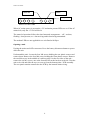
Battery disconnect / Reset button.
This button has two functions – when mains power is present it acts as a reset button.
When mains power is lost and the unit is running from the battery, it disconnects the
battery and the unit powers down. Note - to prevent damage to the battery, a low
battery voltage detector automatically disconnects the battery and powers down the
unit if the unit runs without AC mains power for an extended period of time.
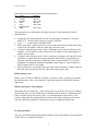
Front panel LEDs.
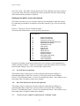
There are six LEDs showing through the window on the lower RHS of the membrane
switch. They are assigned as shown –